

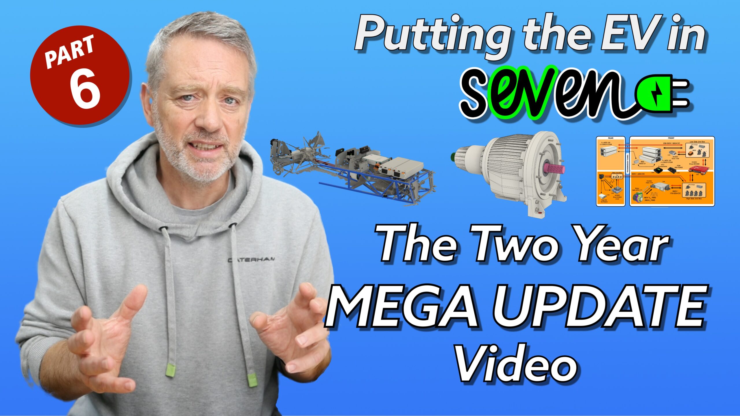
Well… I finally got to the point where I realized I wasn’t going to be able to upload all the videos I’d wanted to.
For the whole of my Putting the EV in Seven project, I’ve been taking video and pictures in order to put together a series of progress videos for the project. But now being over 2 years behind on this, I decided to cut my losses and just put out one, too long, update video.
And that’s what this video is. It does go through how the project got to where it is now, but it doesn’t cover all the minutia (thankfully, I hear you say).
I cover this a bit in the video, but I also decided to try and keep the production effort down to a minimum from this point on. I’d been spending way too much time on fancy blender animations (like the Permanent Magnet Motor and Engine Cooling animations). So this video is just me talking to the camera about what’s been going on.
Here’s the chapter list from the video:
- 00:00 – Start
- 00:41 – Quick video update
- 01:11 – Where had we got to
- 01:51 – But that was two years ago!
- 02:32 – Chassis Model
- 03:30 – What’s the first component decision
- 05:15 – It’s Helix for the Motor and Inverter
- 06:10 – Decision #2 Battery Selection
- 06:57 – Initial Vehicle Dynamics
- 10:31 – WE need a single speed Gearbox
- 11:09 – Can I build my own single speed Gearbox?
- 12:31 – Compact Orbital Gears
- 13:13 – Compact Orbital Designs Planetary Gearbox
- 14:55 – Gearbox Cooling and Lubrication
- 17:57 – Gearbox Status
- 18:45 – Battery Pack Basics
- 19:34 – Traction DC2DC Converter
- 20:46 – We’ve got all the main components
- 21:30 – Final Vehicle Dynamics
- 23:03 – Block Diagram
- 29:07 – Space Planning
- 29:40 – Motor and Gearbox Placement
- 30:38 – Chassis Mounting Points
- 32:10 – Sub-frame Placement
- 34:07 – Traction DC2DC Converter Placement
- 34:23 – Front Battery Box Placement
- 35:09 – Inverter Placement
- 35:42 – Rear Component Placement
- 36:26 – Differential and Gearbox Relationship
- 37:05 – Does it fit under the Nisecone and Bonnet
- 37:28 – Ancilliary Component Placement
- 39:32 – 3D Printed Scale Model
- 43:10 – Walk around the Project Car
- 43:39 – Recent Updates
- 45:54 – Costs… not yet!
- 46:37 – Next time…
- 46:51 – Sign off
Other Comments from the Video
Most of the important stuff is in the video. I talk about the overall journey but there’s probably a bit missing about timelines that might be useful to cover:
- 2021 Decided I was going to do a sEVen
- 2022-08 Purchased Project Car
- 2023-03 MOT’ed
- 2023-05 Road Registered
- 2023-06 Strip Down
- 2023-07 Scanning
- 2023-08 –> Initial designs around rear Swindon Power Train motor and Cascadia Inverter
- 2024-03 Rear suspension sub-project
- 2024-03 That all didn’t work out, so switched to motor in the transmission tunnel
- 2024-04 Found Helix
- 2024-01 Found Brusa BDC668
- 2025-09 Helix SPX-177 and CTi-4 ordered
- 2024-10 Brusa BDC668 Ordered
- 2025-01 BDC668 Arrived (4 month delivery cycle)
- 2025-04 Helix SPX-177 and CTi 4 arrived (they were on a 6 month delivery schedule, but took longer than that in the end)
- 2025-01 Started working on my own gearbox
- 2025-04 Started looking for gearbox manufacturers
- 2025-05 Found Compact Orbital Gears (COG)
- 2025-08 Contracted COG
- 2025-09 Final decision to do 6 battery modules (had been planning on 4 previously)
- 2025-10 Other Ancillaries decided on
- 2025-11 Ancillaries and Batteries Purchased
- 2025-12 COG Gearbox Design Complete
So what’s not in the video?
I had a whole video series worked out for the following that didn’t get made…
- Rear motor planning
- Dual rear motor planetary gearboxes
- Rear suspension dynamics mini-project
- Lots of thoughts on space planning different options
Now up to date
So that’s the project pretty much up to date. That releases me to do two things.
Firstly, I’m going to be able to get more videos out. I was reluctant to put short updates out, because there was a whole chunk of unexplained issues that weren’t published and wouldn’t therefore just confused everyone.
Secondly, I’ve been holding off putting out more of these ramblings on this site… for the same reasons. And I also didn’t want to publish here and not have some YouTube content to go along with it. So… I should now be able to ramble on here a bit more now… lucky you!
Final Cut Pro Edit

Video Chapters
- [00:00] Start
- [00:41] Quick video update
- [01:11] Where had we got to
- [01:51] But that was two years ago!
- [02:32] Chassis Model
- [03:30] What’s the first component decision
- [05:15] It’s Helix for the Motor and Inverter
- [06:10] Decision #2 Battery Selection
- [06:57] Initial Vehicle Dynamics
- [10:31] WE need a single speed Gearbox
- [11:09] Can I build my own single speed Gearbox?
- [12:31] Compact Orbital Gears
- [13:13] Compact Orbital Designs Planetary Gearbox
- [14:55] Gearbox Cooling and Lubrication
- [17:57] Gearbox Status
- [18:45] Battery Pack Basics
- [19:34] Traction DC2DC Converter
- [20:46] We’ve got all the main components
- [21:30] Final Vehicle Dynamics
- [23:03] Block Diagram
- [29:07] Space Planning
- [29:40] Motor and Gearbox Placement
- [30:38] Chassis Mounting Points
- [32:10] Sub-frame Placement
- [34:07] Traction DC2DC Converter Placement
- [34:23] Front Battery Box Placement
- [35:09] Inverter Placement
- [35:42] Rear Component Placement
- [36:26] Differential and Gearbox Relationship
- [37:05] Does it fit under the Nisecone and Bonnet
- [37:28] Ancilliary Component Placement
- [39:32] 3D Printed Scale Model
- [43:10] Walk around the Project Car
- [43:39] Recent Updates
- [45:54] Costs… not yet!
- [46:37] Next time…
- [46:51] Sign off
Transcript
Start
[00:00] Hi, I’m John Martin and welcome to another Purplemeanie. Project 7 update video. And this video… I’m going to be covering the overall architecture both mechanically and electrically of this project 7, where I’ve got to at the moment, which is pretty far. And I’ll be covering a couple of fairly unique features to this project. And is going to raise a couple of eyebrows, I think in the process. So, uh, Let’s get into it. I’m also not going to do. The whole 2 years worth of project videos.
[00:27] that I was planning to do. I’m going to give you today an update, get you up to date with where we are. And if some of that history comes. up of the last 2 years in the forthcoming videos, then we’ll pick it up there.
Quick video update
[00:44] The plan is to drastically cut down on the production of these videos. None of the fancy engine cooling animations or the… electric motor animations that I’ve done in previous videos. This is going to be a lot more me talking to camera like this, and hopefully, that means I can get a few more of these videos out a bit more regularly. We’ll have to see how that works. But before we get to the recent updates, I think I need to give you an update on where we are at the moment with the project.
Where had we got to
[01:13] As I left you in the last video, we’d 3D scanned the car and the car had been MOT’d. which is government test, which means I could get it. registered for road use. Remember, this is an X drift card that had never been used on the road. And that would mean that with the car registered as an internal combustion engine car, hopefully the process of re registering it as an electric vehicle would be easier with our government authorities. So that was planned.
[01:41] And that left me with a car that had been stripped out. And 3D scanned, ready for me to figure out what the space planning is going to be of this project. That’s where I left you in the last video.
But that was two years ago!
[01:53] So while that 3D scanning video went out just a few weeks ago, in reality, it was actually 2 years in this project timeline. And I’ve been working pretty much full time on this project for that last 2 years, but it’s only now that I’ve got to a locked down component list and a very definite understanding of how it’s all going to play out, which, for sometimes in this last 2 years, has been fairly fluid, and things have, I’ve had some fairly big setbacks, um, and had to completely rethink how I’m going to go and do things.
[02:23] But as we sit here today, I’ve pretty much got the whole project ready to go and that felt like a good time to do a project update video.
Chassis Model
[02:33] The first thing I needed was a 3D model of the chassis. I had the scans from the Previous video. But they’re a bit heavyweight, and I needed something that I could use in CAD a little better, so I decided to create myself an accurate 3D model of the chassis I was working with, and I decided to do that in Blender. Once I was in blender, I could add an empty to the end of each chassis rail. And then using geometry nodes, connect them up.
[03:02] With tubes. So that when I moved, The empty around, I could position the chassis rail in exactly the right location in the mesh. Then once I had enough of the chassis that I needed, I could export that to Fusion 360. Okay, so now I have a chassis in. Fusion 360. I can also bring in the mesh if I want it. And now I’ve got a pretty good representation of. the car… What sort of space I’ve got? to be able to use.
What’s the first component decision
[03:31] So I now have a 3D model of the chassis in fusion 360 along with the mesh that I can use as well. The 1st thing to be working out in a conversion project is. what motor you’re going to use and where you’re going to put it. And that’s where I spent a fairly big chunk of the 1st part of this 2 years that I seem to be skipping over. Ideally, I would have liked to have had a motor sat in the rear of the car.
[03:55] That would have meant that I could get rid of the existing differential, and the prop shaft would have gone. Of course, I’ve lost the gearbox and the petrol motor and all of the radiators and cooling and all of that stuff is gone as well. And I can obviously lose the fuel tank. So, ideally, I want to be getting the motor in the back, and I started to look at a whole bunch of different options around rear motors. But on closer inspection, nothing seemed to fit.
[04:23] I tried the standard stuff like everybody suggests a Tesla and an outlander motor, but they just wouldn’t fit. I had a whole separate mini project on looking at how the suspension moves up and down in a… Cater and to see how much travel I had on the D on tube, I built a… whole bunch of electronics and drove my… Petrol car around to see how much the suspension has moved up and down. But the options I was looking at, none of them seem to fit and all seem to foul on the Didion tube.
[04:52] I even tried a twin motor rear installation with twin. planetary. 6 to one gear reduction boxes sat on the outside of the motors going to… drive shafts that I would have to have made. But in the end, that didn’t work out either for various reasons, and so I had to junk the idea of having the motor in the rear of the car.
It’s Helix for the Motor and Inverter
[05:17] So that wasn’t going to be. It was back to the drawing board, and eventually I landed on a motor and inverter. Pair from a company called Helix in Milton Keynes. And remember that I’m trying to get the best sort of performance I can out of this system, so I’m looking for performance similar to my. Caterum 420 R, which has a not 60 time of around 4 seconds and a top speed of 130 miles an hour. So I’m looking for some dynamics that are round about that sort of capability.
[05:45] And the motor I landed on from Helix. Would fit in the front of the car just in the transmission tunnel. And it’s a pretty good spec. 240 kilowatts. But that comes at the price of it being an 800 volt system, which is one downside. And secondly, it runs to 24,000 RPM, which was also going to be a challenge that we’ll get into in a bit.
Decision #2 Battery Selection
[06:11] So I was going to need to feed all of that power 240 kilowatts with some batteries, and in the end, after playing around with a lot of different module options, and pack sizes. I landed on being able to use 6. MEB, Volkswagen. Battery modules that are fitted. in ID3s, ID4s, that sort of vehicle. And 6 of those modules gives me around about 40 kilowatt hours. It gives me very high current capability, which we’ll come onto in a little bit and it gives me a voltage that I can work with, again, that we’ll come to in a little bit.
[06:51] But, uh, So I’ve got motor inverter and some batteries. What’s next?
Initial Vehicle Dynamics
[06:59] So with a few of the basic components figured out, where do we go now? Well, it’s time to start looking at how this car is going to perform and what we’re going to be able to expect in terms of speed, range, not 60 times, those sorts of things. And I’d been running with a whole bunch of my own spreadsheets, and that was working out fine, working out all sorts of losses and acceleration times and so on. But about this time, there was a spreadsheet posted to the open inverter org forums, and a user had very kindly created and made available a vehicle dynamic spreadsheet.
[07:36] that really Packaged all of my spreadsheets into a single place and allowed me to start playing around with how this vehicle was going to perform. I’ll put a link to the forum post with the spreadsheet in it in the video description notes below. So here we are in the retro VMSEV designer, and I’ve got this set up with some of the basic dynamics of the car, things like weight. The maximum power of the motor. How much? talk, I’m going to be able to deliver with the battery back that I have.
[08:05] The maximum speed of the motor. And I’ve got some of the other dynamics setup, like the differential final ratio, cell voltages, capacity of each of the modules, how many cells I’ve got in series. I’ve got 6 packs with 12 cells each. So that’s 72 cells. And this calculates things like pack voltage, current. Some other stuff. However, with all of that set up, we can see that the nought to 60 time is going to be 13 and a half seconds. We get a reasonable range, 169 miles, pretty good.
[08:45] Top speed, okay, 116 miles now. But it’s this not 60 time that’s given me some concern at the moment. The problem here is that this is a little too pedestrian. You’d be using this all the time, that about this sort of acceleration in order to just drive around town. So I don’t want that sort of vehicle dynamic. in this 1st iteration. So what can I do about it? Well, it turns out that there’s a couple of other things going on here.
[09:12] If we have a look at the CAD, you can see that I’ve got the motor fitted into the transmission tunnel as far as it would go. But if I bring in the differential and this red pipe showing where the output flange of the differential sort of points towards… The motor. The length between the differential and the motor. is now. Quite long. And if I’m going to connect the prop shaft directly to the motor, I’ve got a shaft length between the 2 universal joints that is going to cause me problems.
[09:43] Having contacted bailey morris, the people who make the prop shafts for caterums. They have a graph of maximum permissible RPM against. The length of the prop shaft, and as you increase the prop shaft, the maximum permissible RPM reduces. And at the length I’ve got here between the motor and the differential, I’m not going to be able to run the prop shaft at the speed I need to achieve the 2000 RPM at the wheels. There’s knock on effects everywhere in this project.
[10:11] As soon as you look at one thing, another thing pops up and says, ah, that’s not quite gonna work. So, I have 2 problems here. I have a vehicle dynamics where the acceleration times are not looking particularly good. And I’ve got a spacing problem where my motor is too far away from my differential. So the solution is a gearbox.
WE need a single speed Gearbox
[10:33] I searched all over for a gearbox that would fit into this project. There’s all sorts of stuff out there from sort of motorbike gearboxes. existing using the existing case from gearbox, was that going to work? Uh, there’s uh, drags to gearboxes, copes with huge amounts of power. But for one reason or other, none of them are going to work. Even with an adapter plate going from the motor into the gearbox. They were either too big or they wouldn’t run to the 24,000 RPM or they couldn’t cope with the power or they couldn’t cope with the talk.
[11:05] Uh, none of these were going to work uh, the way I wanted them to.
Can I build my own single speed Gearbox?
[11:11] So, I started to think about how I could design my own gearbox. I’d looked at designing planetary gearboxes to go on the twin motor solution I done probably a year before this, and I decided that I could probably put something together and see if I could go and get it manufactured. But even with a pretty good model to start with, I wasn’t very confident that I could make this work in the real world. Theoretically, it all worked okay and um, I even…
[11:39] couple of prints designed that seemed to show what I was doing. But I wasn’t confident that I could make this work myself. So I studied looking around for someone who could help me out. And I found a few options in people that could make gearboxes for me. But in the end… They weren’t really confident about the 24,000 RPM, the power, the talk. I wanted to go with helical cut gears. So instead of straight cut gears. I wanted helicol, and this was going to help with the noise.
[12:12] This running at 24,000 RPM is going to scream like a banshee if we don’t get this design properly. So it needed to be helical. And all in all, couldn’t find anybody that was going to be able to do that for me. So options weren’t looking good at this point until I was introduced to a company called Compact
Compact Orbital Gears
[12:32] Orbital Gears in Mid Wales. They’ve spent the last 60 years developing planetary gear systems for all sorts of applications from. 125,000 RPM. Aerospace motors. All the way to 2 meter wide, winter buying planetary systems or… things that go into diesel electric trains. So they got a huge experience in developing these systems and so had a chat with them. I provided my sort of concept. how this is going to work. And the idea was they were going to essentially productionize this.
[13:05] We agreed on a project timescale and a plan and they got to work creating a gearbox.
Compact Orbital Designs Planetary Gearbox
[13:16] And this is pretty much what we ended up with. This is very close to the final design. There’s still perhaps a few days work left in it, but this is where we’ve got to. Again, the… Motor input is here. The prop shaft output is here. The basic specs of this are. A… 24,000 RPM input speed, maximum talk of 200 Newton meters, power of 240 kilowatts. And it needs to have a minimum dimension, front to back of around 230 millimetres. This is bigger than that.
[13:51] And. It needs to be able to cope with. standard road use, um, regular, a bit of track use, and uh, it also needs to be able to cope with both uh, motoring, so driving uh, forward, which is uh, Clockwise direction in, in this view, and… It needs to be able to cope with reversing at sort of a few percent of maximum torque. We’re not going to reverse very quickly. And it also needs to cope with regen. So that means that the motor has gone from producing positive talk, to negative talk at around about 20 to 50% of the standard talk level.
[14:37] And that’s really where we’ve ended up. It’s a very nice design that I would not have been able to come up with On my own. The guys at Gog have really pulled out all the stops here and we’ve got a lovely gearbox.
Gearbox Cooling and Lubrication
[14:56] So one of the downsides of all of this is that with the speed and the size, we’re running at 24,000 RPM, less than 200 millimeters in diameter, One of the problems is that the speed at which the gears are running, the pitch line velocity is much higher than a passively called system can cope with. Usually that’s around about 24 meters per 2nd for a passively cooled. gearbox. Once you get above the 24 meters per second, you have to start talking about external cooling systems and being able to pump colon into the box and out of box.
[15:35] So… One of the consequences is that this is going to need an external cooling and probably going to need a uh, well, it will need a radiator uh, to cool the oil. This is going to be a very efficient gearbox. is a planetary system. But the losses are still going to be at full power something around about 3 kilowatts. So you’ve got something here that’s the size of a shoebox or so, and it needs to dissipate 3 kiloatts of power, and it’s not going to be able to do that passively.
[16:09] So we’re going to need to put some cooling, oil through it, and put a radiator on it, and that comes with extra complexity. But we’ve got a high power unit, run at a high speed, in a very small space. It’s not unreasonable to expect that I would need external external cooling on this. So with that in mind, let’s have a quick peek at what’s inside this gearbox. As you can see from this cutaway, things are pretty complicated inside. There’s oil inlet that feeds oil down through all these chambers, pushes oil out into these bearings, there’s bearings here, here.
[16:50] We’ve got Berings, roller bearings in here, in the pins, bearings on the output shaft, all of these need to be oiled. And then we’ve got a bit of a sump at the bottom and an oil exit. So, it’s a really complicated system, uh, let’s show you with the uh, with the casing off. There we have it with the casing removed. can see, there’s an awful lot of fixings. We’ve got a outer ring gear. Let’s hide that. And you can see the planets in here.
[17:27] Where you just hide one of those. You can see, uh, roller bearings, and uh, the sun shaft stuck in here. So it’s a really complicated gearbox and I would not have been able to get to this level of complexity. Just… Wasn’t in my wheelhouse at all. And so I’m very happy to be working with Cog and looking forward to getting this manufactured.
Gearbox Status
[17:59] We’re now at the point where this box is designed, there’s perhaps a couple of days left in the design work and we’ve moved into manufacture. in the next couple of weeks. So as we sit here at the moment, update video, we have the gearbox designed. But there’s still a bit of a fly in the ointment. If we look back at the vehicle dynamics spreadsheet, the eagle eyed amongst you will notice that the voltages and currents don’t quite add up. There’s something we’re going on with the low voltage 276 volts and being able to deliver the sort of power that I’m looking at.
[18:38] So, the fly here is the 800 volt motor.
Battery Pack Basics
[18:46] So to back up a bit, you need to be thinking about the lithium ion batteries and the way they get configured in a battery pack. They get configured in multiples of their sort of fundamental cell voltage, which is around about 3.7 volts, and you need to stack a bunch of those up in series to go from your 3.7 for one cell up to the target voltage you have for your application, in this case, 800 volts. And that works out at around about 200 cells.
[19:16] And I just haven’t got the space for that. I could start looking at building my own battery pack. But I haven’t got the time or the inclination to go and do that. So how am I going to solve this problem? I need to get to 800 volts for the motor, and I haven’t gotten a voltage from my battery pack.
Traction DC2DC Converter
[19:35] Well, there’s a simple electronics engineer type solution to this that we would typically do, which is what’s known as a DC-DC converter, which takes a low voltage at a high current and converts it to a high voltage at a lower current. Power is conserved across the two. But essentially, this is a known piece of technology. The problem here. is I’m doing this at 240 kilowatts, and I need to fit that in a car. The size, one of the smallest cars on the road.
[20:07] So I need to find a very compact but high powered DC-DC converter. And this was something I started looking around at early on in this motor journey. Once I’d picked the helix motor. I knew the 800 Volt system was a problem. I started looking around. I found a couple of different sorts of solutions. But I landed on the Brucer BDC 668. It’s a very high power. High current. High voltage, designed for electric vehicle applications, fuel cells, and battery electric vehicles.
[20:38] It’s the sort of size that would fit into the car. And Brucer had just launched this at the point where I was looking for a solution.
We’ve got all the main components
[20:48] So that’s all the major components really tied down. Some were decided on years ago, very early on in my two-year journey that I’m documenting here. But someone… came into the frame recently, uh, like the gearbox. So we have a motor inverter. We have attraction DC to DC converter, which is what I’m calling the Brewster device. We have our battery modules. And that means we’ve fixed both the 800 volt problem into the motor and inverter. and the distance between the differential and the gearbox, with a now very acceptable 9000 RPM.
[21:22] allowed rotational speed. And that gives the vehicle a set of dynamics. So if we jump back into the dynamic spreadsheet.
Final Vehicle Dynamics
[21:32] If we now plug in our gearbox, With a ratio of 3.5 to one. It completely transforms the car. We now have a nought to 60. time of 3.4 seconds, which by any body’s measure is going to be okay. Top speed of 160. miles an hour and a range of about 170 miles. We’ll take that with a pinch of salt. All the acceleration curves are looking pretty good. We’re only using our maximum talk that we can get with the 600 amps that we can deliver from the battery pack and the 133.
[22:09] meters that that is going to allow us. This gives us, we are torque limited up to around about this nought to 60 time, and then we are power limited, because the vaults times amps gives us our power, we’re power limited from that point up to a total RPM of around what, 22,000 RPM on the motor. So within the design spec. Whether this translates into real world dynamics, we’ll have to see. I have plugged in. To… other different cars into this one electric vehicle that we own.
[22:43] And the Purple 420 Caterum 7 also I put into this and… allowed for it being a petrol car. And this spreadsheet gives pretty much the results I would expect for both those cars. So I’m hoping it’s there or thereabouts for this Project 7 EV conversion as well.
Block Diagram
[23:04] Okay, so that gets us to the major components, motor inverter, battery pack, and gearbox. We’ve got a whole bunch of other ancillaries. We going to need in our electric vehicle as well. And we can cover that in a couple of ways, but I’m going to start off with a block diagram of what the whole of that electronics looks like. from a high… Voltage perspective. So here we are with the block diagram, and I’ve sort of broken this down into the rear of the vehicle, which you can see on the left-hand side and the front of the vehicle on the right-hand side.
[23:35] So at the back, we’re going to have a couple of battery modules and these black things on here are the battery management system. So that controls the charging of each of the modules. It looks at each of the voltages of each of those cells in series and decides how we regulate. The charging of the battery. but also the conditioning of the battery. So in the rear, we’ve got a couple of modules. I’m going to put the charging port the back. We’ve got the option for a DC charger that I won’t probably put in the beginning.
[24:06] We’ve got an AC to DC charger, so that’s taking alternating current from the charging port and converting it to DC current. Got a junction box in here. So that allows me to run a charging at around about 400 volts on this bus here, but then at 800 volts later on if I’m driving the motor. So there’s a bit of jiggery pokery going on here to make sure that this. Charging connector doesn’t connect to the 800 volt system. And it protects this charger as well from the 800 volt.
[24:39] So that’s the rear of the vehicle. Moving to the front, we’ve got, again, 4 battery modules at the front with their battery management systems attached. This is a controller for the battery management system from a company called Imus. Emus. which I’ve bought from the guys that I got the modules from. We’ve got a DC to DC converter here. This goes from the high voltage of the battery, so the… Uh, 200 odd volts and converts it to 12 volts. For running things like the lights, ancillaries, all of that sort of stuff, the standard electric stuff that is already in the ice car needs to get run off 12 volt system, and I’m not going to replace that.
[25:25] So I need to go from the high voltage of the battery down to 12 volts, 12, 14 volts for those ancillaries and that’s what. thing is doing here. Then I need a junction box here again to do precharge. When you’re connecting high current batteries to other components in the system, these are the components like this traction DC to DC converter, has got a lot of capacitance in it, and if we were to connect the batteries directly, To the converter. There would be a lot of in-rush current.
[25:54] So these contactors, the things that you can hear go click, click on an electric car when you start it up. Those are the contact is opening and closing to create a pre-charge. limits the current flow into the devices you’re trying to protect. And protects them from inrush current and burning up. So then we’ve got the traction converter here. This is both a boost and a buck converter, so it will run a boost taking a low voltage and converting it to a high voltage, low voltage to a high voltage, and it will also go in reverse.
[26:25] So when we’re doing regen, it will convert as a butt converter from the high voltage coming from the drivetrain back into a low voltage to go into the battery pack. So this is quite a complicated bit of electronics. And we’ll need a lot of controlling. We then got another junction box on the high side, so this is all the high side in this dark orange, and this high side junction box, not… quite sure at the moment, big question mark on this as to exactly how this is going to look.
[26:57] I might even be able to get away with it using some fancy control of this DC to DC converter, but we’ll have to see how that goes. And then the 800 volts that’s created by this traction converter goes through an inverter, so converting from DC to 3 phase AC, sinusoidal waveforms, what we talked about in one of the other videos and into the motor. This is a power delivery module from aim. It’s got 32 outputs on it that fairly high current automotive style outputs.
[27:33] that I can control from a canvas to turn these contactors on and off. There’s a lot of these contactors you can see around the place. And I’m going to need a lot of control lines to turn them on and off at the right times. But also things like running pumps using pulse width modulation and some other stuff that we’ll get into in some future videos. And that all needs to be controlled by a vehicle control unit. Now. There’s a lot of ways of doing this sort of stuff, but it has to be pretty much automotive grade.
[28:01] Um, so we can’t really do it with something like a raspberry pie or Aduino. So I’ve gone with an open source. Zombie Verter from… Open inverter.org. And the guy… that runs a business called EV. BMW. And he sells… The zombie verter kit, and then there’s an open source project that provides the software. The software is very… Modular and it runs along the concept of… Device drivers. So I’m going to need to write code for all of. The new bits that the zombie verter doesn’t currently support like my traction, DC to DC converter, and my inverter will need drivers written for them.
[28:35] So that is. The block diagram, you can see on… Many of these things, there’s the word can. That implies that there’s a canvas connected to that device. And so there’s going to be a couple or 3 even canvuses running around this system where all the… Commander control is. going to be running. So that’s the block diagram from a sort of electrical stance. Let’s go and have a look at how that looks physically in the CAD model and how it might and how it’s all going to fit in the car.
Space Planning
[29:10] Okay, so here we are back in Fusion 360. I’ve got the mesh and the… Blender gen… chassis showing here at the moment. And I’m going to run through how I think this is going to get assembled, broadly assembled. Some of it might look a little bit convoluted, but there are reasons that we may get into in future videos, but for the moment just accept that I think this is the best way to get it assembled. Here we have the chassis and scan.
[29:37] Let’s get rid of this. Scan.
Motor and Gearbox Placement
[29:41] And the 1st thing we’re going to do is bring in the motor and the gearbox. So with the motor and the gearbox in, they’re going to sit in this position. We’ve spent a lot of time trying to figure out how this is going to work and to make sure we’ve got enough wiggle room on the installation. This is all extremely tight on the chassis rails, and the motor and the gearbox will need to be assembled together, and they’ll need to come into the chassis at a lower level and then get raised up so that they avoid this chassis rail.
[30:15] We’ve given ourselves hopefully enough wiggle rooms so that we can move this assembly backwards and forwards. As you can see, there’s some very tight tolerances between things here. But we have got enough room in sort of these sorts of places to be able to move the whole assembly, up, down, backwards and forwards, a little bit, in order to give ourselves a bit of wiggle.
Chassis Mounting Points
[30:39] The next thing we’re probably going to need to look at is how this gets mounted. So the 1st thing to think about here, that is this is going to have to fit. onto the… existing chassis. don’t want to be changing any of the chassis at all. So there are 3 mounting points that the gearbox and… Petrol motor from the ice car get mounted to. So let’s bring those. Back in. So you can see here that we have a rear gearbox. Mounting, metalastic bushing.
[31:10] It sits on the this plate in the chassis, and normally in here, the gearbox would sit, and through the bottom, this hole here would get bolted onto the gearbox. So this plate attaches to the gearbox. This plate attaches to the chassis, and in between, there’s a black rubber metalastic bush. So that gives us one mounting point. If we zoom out a bit and come back to the front. There are two engine mountain points. So these would normally, these are bolted onto the chassis.
[31:46] The engine mounts are bolted through this hole here, and the black bushing here, black rubber bushing, isolates the chassis from the engine mount. So, we’ve got 3 mounting points we can work with. And the idea is, I will create. a sub frame to work between those three. So it’s still a work in progress, but let’s bring that in.
Sub-frame Placement
[32:12] So here’s the subframe. As I’m thinking of it at the moment. It will have, let’s swing around here, some sort of connection between the subframe and the components that sit in the engine bay above it, and okay, gonna make you all sick. Let’s swing back around and have a look at the mounting for the gearbox. So let’s quickly get rid of the chassis. And we can see the metalastic bushing here, and a yoke that sits where the gearbox, the old gearbox would have set to connect this gearbox and attach it around this collar here.
[33:00] This will have a kiwi in it to… Stop the gearbox rotating in this. And then a couple of arms, this still a bit of a work in progress will come off this aluminium, this being steel, bolted together, and onto a subframe that, um, there will be a flange coming off the subframe here connecting to these mountain points. So the gearbox is attached to the subframe and through this metalastic pushing to the chassis. Then the motor is cantilevered off the front of the gearbox.
[33:40] That’s the way it’s designed, that’s the way it has to work, and the mounting adaptor plate that goes between the main gearbox and the motor is taking all of the load of this approximately 20 kilos of Uh, motor cantilevered off front. Okay, so that’s, let’s bring the chassis back in. So that’s sort of how all of that will go in there.
Traction DC2DC Converter Placement
[34:09] So that’s the traction DC to DC converter, and you can sort of see why now this arrangement round… here has got this bar on it. It’s gonna attach to these fixing points here.
Front Battery Box Placement
[34:25] Okay, so this is 4 battery modules with their BMS on the front. There’s a master service disconnect. We’re going to have here, and there’s a couple of contactors that I’ve just sort of laid out in this volume here. Now, around these modules will be an enclosure. I. Folded steel box will go around them, and there will be a frame that goes from the mounting points on top of these DC to DC converter to the battery box, and this will sit on here.
[35:02] I’ll bring in the nose Conan, the bonnet a bit later so you can see how this all sort of fits together inside that.
Inverter Placement
[35:10] So the next component to come in is the inverter. And that will sit something like this with the power cables from the inverted, the 3 phase AC coming out here and into the motor. I like this, and then the… Output from the DC to DC converter going through a junction box into the 800 volt input on the inverter on this side. There’s some control here.
Rear Component Placement
[35:44] Okay, so that’s most of the front sort of sorted out. Let’s bring in some of the stuff at the back now. With the rear battery box, at least in concept. So, I’m assuming a bit on that, couple of battery modules with their BMS. This is the AC to DC charger, so that’s taking the The charge port, AC, and converting that to DC for the battery pack. Let’s put the mesh back on. And you can see that the charged port will basically sit where the current fuel flap is on a Caterham.
Differential and Gearbox Relationship
[36:28] And let’s bring the diff in. And you can see that the diff basically points at the output of the gearbox. You need a 4 degree-ish, uh, different. between the angle on. The input on the… and the output on the gearbox to keep the universal joints which sit in this prop shaft. They’re not modeled. They need those to keep the lubrication of the universal joints working properly. You can’t have a prop shaft running completely co. Linear. You need a bit of a…
[37:03] Anglom.
Does it fit under the Nisecone and Bonnet
[37:07] I have the nose cone. And I have a representation of the bonnet, didn’t, I don’t have a scan of the bonnet, and so I just mocked up some basics of how that might look. And you can see everything pretty much fits in.
Ancilliary Component Placement
[37:29] So we’ve got a few more components in. Let’s have a quick zoom in on those. We’ve got on the bulkhead here. I think we’re going to be mounting the zombie vehicle control unit. The PDM, and probably placed here, we’ve got the… DC to DC converter going from the battery pack to the 12 volt, somewhere we’re going to have to probably find a small space for a lithium iron battery, possibly somewhere around this point here. The aim unit also comes with a display, and I haven’t quite decided whether I’m going to use that at the moment.
[38:04] If I put in the steering column. You can see the steering column runs up through these bulkheads. Down through the foot well into the steering rack at the front. Let’s hide the bonnet, the nose cone, and the mesh. And you can see that the steering column causes a lot of problems in this area. I would love to have been able to get more battery modules across the side of the engine bay here, but the steering column causes all sorts of problems.
[38:37] And in the end, I went with a conservative approach. That gives me a lot of space around here to put the junction boxes that I’m going to need anyway. So it’s not all completely lost. And then at the back, quickly there’s the DC charging controller here, if I get around to that in the 1st phase. So there you go. That’s a look at the space planning for the car at the moment. What’s missing really is the subframe mounting process and the battery boxes that are going to go around these battery modules.
[39:21] Okay, so that’s the sort of space planning of the project. You’ve seen a block diagram of the electrics and you’ve seen how that all sort of physically. I’m hoping to fit all of that into the car.
3D Printed Scale Model
[39:34] At the time I was looking at the gearbox design, I realized the CAD’s fantastic. I really love working in 3D CAD and I would not have been able to get to where I am if I hadn’t been using 3D CAD scanning and that whole process. But I was missing a bit of the what typically people use as cardboard aided design, you know, where you you build up a model of the thing and you can you can play around with it physically in your hands and get a real sense of what it’s going to look like.
[40:01] So at about this point, space planning, gearbox design. I thought I needed something a bit more physical. And so I went away and I printed a scale model of what I was doing. And here we have it. This is the one fifth scale model I’ve printed of the. Chassis. So this was the chassis that taken from the scan, put into blender, and then output to Fusion 360 and created an STL to print. You can see we’ve got the gearbox and the motor in here, some of that chassis subframe already modeled, but the idea is that the steering column comes out.
[40:46] The DC to DC converter goes in.
[40:53] A couple of battery modules.
[40:58] Couple more battery modules. The inverter. The DC to DC converter. And then, if we sort of shift all of that over a bit. At the back, there’ll be 2 more battery modules, the AC charger, and the charging port.
[41:28] So before we finish up, I just wanted to cover a couple of those eyebrowser sort of items that I alluded to earlier and we’ve covered a little bit, but the Traction DC to DC converter and the gearbox. The traction DC to DC converter is… A rather large, overpowered piece of equipment. The… Possibly a bit of a luxury in this design. I could have perhaps found a different motor or found a different way of doing things. But it’s not uncommon to find these types of devices in electric vehicles.
[42:02] They’re often called boosts or eye boosts or something like that. And they’re fairly common to take a low voltage and create a higher voltage or to provide a bit of extra boost power or something. in the drivetrain. So it’s not unusual to have a DC to DC converter. Mine’s just a very high powered one. And on the subject of the gearbox, Well, Of the, I think, six, seven… type cars that I’m aware of. 3 of them. Have got. He the… Custom or.
[42:33] Heavily modified gearboxes in them. Mine’s one of those. So, again, this gearbox. It might be quite a high spec one that I’ve ended up with, but it is not something that is uncommon in a 7 conversion. There’s just so little space and such high performance that you end up with needing something like a DC to DC converter and something like the gearbox I’ve gone with. So I don’t think they’re unrealistic for me to be putting into my design. So, um, Just wanted to cover those 2 points off before I get a lot of comments about that.
Walk around the Project Car
[43:11] This is the current state of Project Car. It’s looking a little bit sorry for itself, covered in 3D scanning Markadots, in case I need to get the scanner and get out and test something, but it’s in pretty good condition. And my next job is going to be to get the diff out so I can get access to the prop shaft. Prop shaft won’t come out unless the diff comes out. So that’s my next job.
Recent Updates
[43:41] Right, so that sort of brings us up to date with the design, the space planning, block diagram, and how all of that is going to work. So what have I been up to recently? Well, Now that I’ve got the gearbox pretty much tied down and I know that’s going to work, I could then start to buy some of the other ancillaries that I knew I was going to need. So recently, I went on a road trip and I bought the battery modules from…
[44:04] life EV batteries down in Bournemouth. Six modules brought them back in my van. Got them now installed in my office. And they’re going to get used over the next few weeks. Back. Under here. I’ve ordered and had delivered the AC charger, the low voltage DC to DC converter. I’ve got a charge port now arrived. The BMS has arrived with the battery modules. And the zombie verter, VCU has been ordered from EVBMW in Ireland. Damien’s shipped that to me now and that should be arriving in the next couple of days.
[44:41] So, I’ve now got pretty much all of the components I need to start building up a test rig. I’m going to put all of this into a rig in my office back here. It’s all sort of lying in boxes and getting ready to be put into a. Construction that. Allows me to build up wiring, harnesses, test the software, write the driver modules that I’m going to need for the vehicle control unit, plug in an accelerator, brake sensors, kill switches, all of the things I’m going to need for a 1st installation into the car.
[45:16] I’m going to get running on a desk first, make sure the software works properly. It then goes put into a car, which is sat on axle stands, and the 1st tests for probably the 1st few weeks will be of it sat on axle stands, not moving anywhere, until I’m perfectly happy that the failsafe switches I’m going to put in, can get me out of trouble if I get into any problems. And that’s all going to be happening at about the same time that the gearbox is getting manufactured.
[45:44] And hopefully by the time that’s ready in a few 2 or 3 months time, I’m going to have a lot of the software and cabling built up ready to go.
Costs… not yet!
[45:56] One thing I haven’t talked about is cost. I’m going to cover that in our later video. This is not a cheap project. This is not getting an EV conversion, like you’ll see on some YouTube channels, where they’re trying to put this together for a few £1000 slash dollars and getting the cheapest EV conversion done. It’s also not one of the conversions. We’ll see from electric classic cars or felt. where they’re trying to create a an EV drivetrain that can be installed by anybody.
[46:22] I’m somewhere sort of in between. I hope the production quality of the Feltons and electric classic cars, but it’s me in a shed, doing it by myself, and that means it’s taking an awful lot of time to get this done.
Next time…
[46:38] The next updates are going to be me putting the test rig together, building up harnesses, getting a schematic together, building it all up, and making sure that it works on a test bench before it goes into the car.
Sign off
[46:52] So I hope you’ve enjoyed this update. It’s 2 years of work crammed into a longish video, but hopefully you’ll see that there’s a lot of effort gone into this. And where I’m going in the future. As I always sign off on these videos, uh, if you’re in the cater on world, you know what I mean by blatting, so I’ll say, Stay safe and happy blatting.

Leave a Comment