

This week has been a bit of a wash. We were away last weekend (which is why the updates stopped) and I’ve had a couple of days out and about this week. So only 2 or 3 days on the project.
Gearbox
I’ve had some progress on the gearbox this week. I’ve finally got a quote (don’t ask) for producing the 6 main hardened steel component types that I’ll need. These are the 3 gear components (sun, planets, ring), planet-pins x 2 and the output shaft. I’m almost certainly going ahead with the quote, but it’ll be a 20-week build time 🙁
The remaining components, sort of, fall into two further groups. There’s the four Aluminium casing components, then basically everything else that’s left.
At the moment I’m most keen on getting the casings 3D printed. I’ve found a crowd in the UK that can do it and also a Chinese company that comes recommended. So between the two of them 3D printing should be possible. There’s all sorts of challenges with 3D printing, and the components will need a lot of post-machining, but the wastage is much lower as you don’t need to hollow out the component from a huge great billet. The biggest component is around 200 × 200 × 200 mm and is essentially hollow with about an 8mm wall thickness. That’s a lot of material to remove from the inside… if you’re machining it from billet. 3D printing obviously only has to build up layers of just the walls as they’re needed.
For the “remaining” components, they should be relatively easy to get made by most engineering firms, so I’m not too worried about them at the moment.
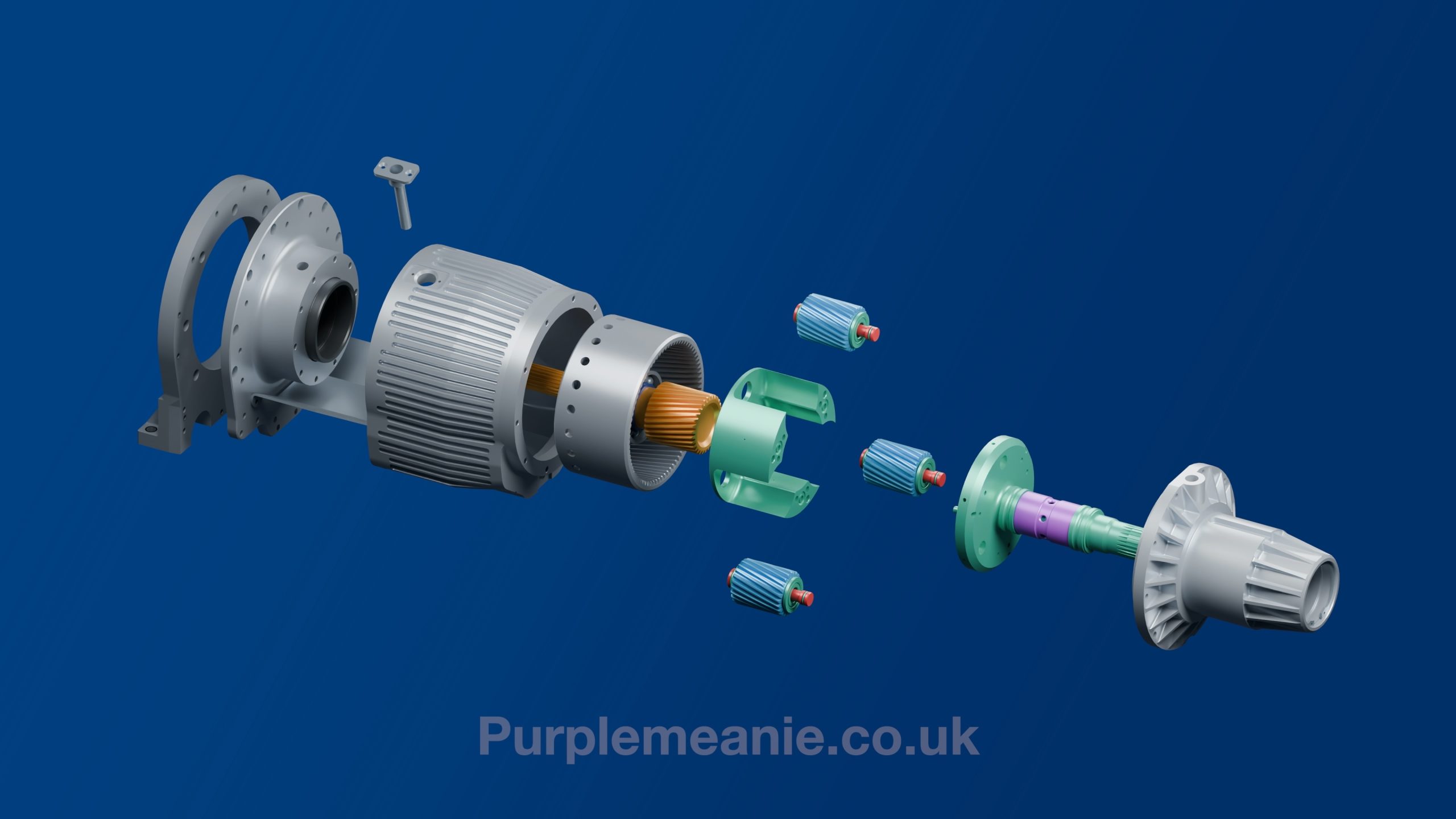
Last weekend I also created a new gearbox animation for someone who was quoting for me. This is another astonishing AI thing… I gave ChatGPT Codex a copy of the 3D model of the gearbox, told it what the gear ratios were (though it figured that out too from the geometry) and then asked it for an exploded view and an animation of the gearbox working. (And if you’re into this stuff then it used Fusion 360 to get the model and then Blender to render out the animation). I’ve done these sorts of Gearbox animations, on older versions of the gearbox, in Blender, by hand myself and they’ve usually taken me a few days. Codex took a few minutes to create the Blender files. I then went back and forth on some cosmetic niceties over an hour or so… each time Codex took a few minutes to add my changes. Then I rendered the whole thing out in 4k – which ran overnight. So Codex saved me days of my time for something that I used to find fun, but now find a bit of a chore after doing it 4 or 5 times over the past 2 years.
Animation to follow… Bonkers!
Powertrain Earthing
I also spent a day or so this week mucking about with the earthing of the main powertrain components: traction DCDC converter, inverter and motor.
I’ve been seeing quite a lot of common mode noise being injected onto the inverter CANbus when the Inverter is in its operating mode. See next image…
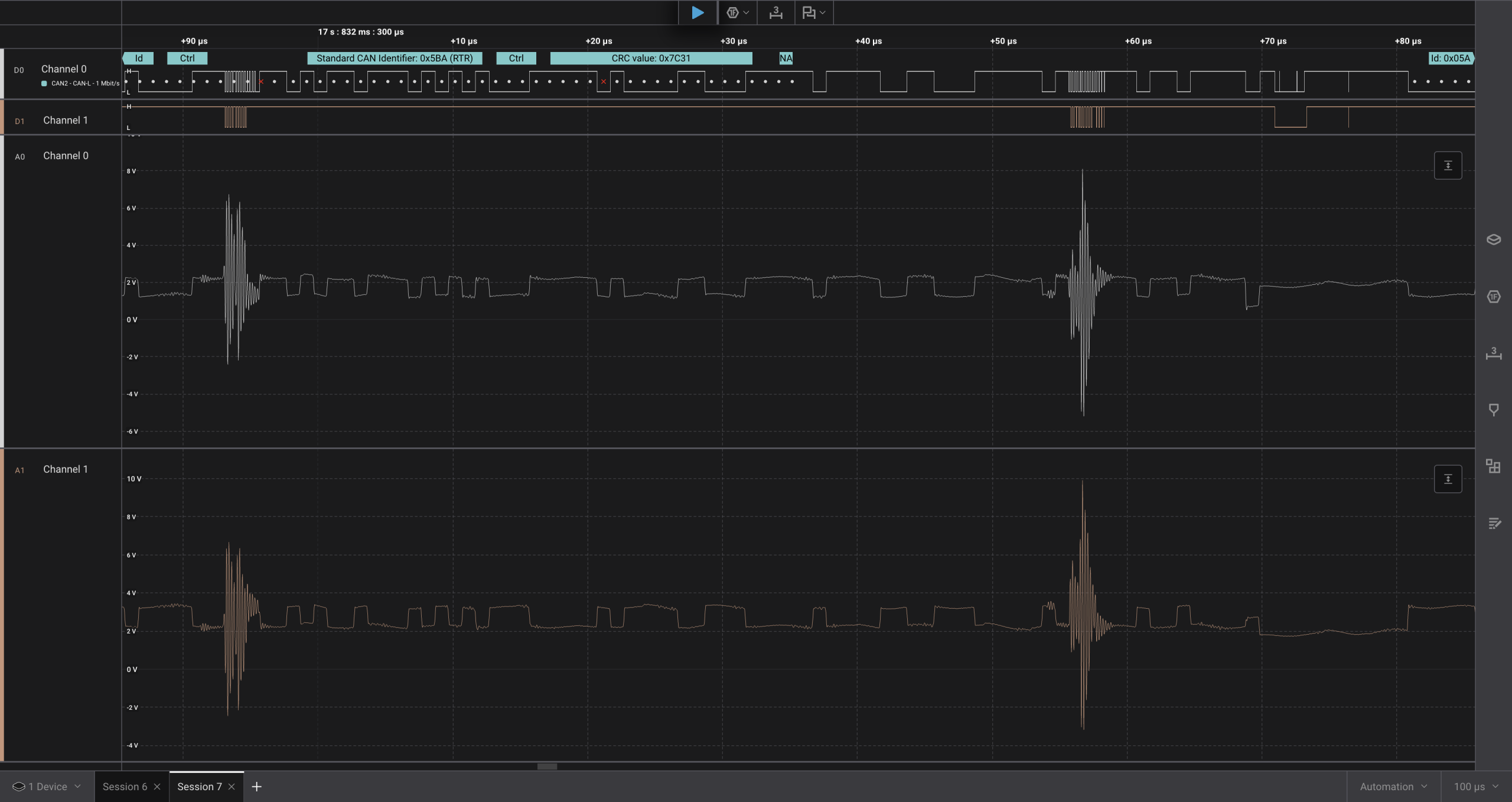
One theory was that the powertrain earthing might be a bit lacking – i.e. there wasn’t any. It hadn’t been a priority, so I hadn’t added it… yet. So I spent a day or so making up some relatively beefy (6 mm²) cables to run between the components and the power supply.
Here’s a quick video of the earthing. If anyone has any comments then I’m all ears!
It made bugger all difference. So I suspect I need to take another look at the inverter power supplies. Helix say this noise is mostly expected… but I’d like to get rid of it if I can.
Battery Management
While I was mucking about with cabling, I’ve also been looking this week to get my “high voltage” batteries connected – instead of a bench power supply.
This wasn’t quite as simple as it first appeared. The HV batteries are second-hand VW ID3 battery modules. They were mostly charged when I got them a year ago, and they’ve not really lost any charge since then – that’s good news… And is an interesting data point for the people who always ask me how long EV batteries last if you don’t use your car.
Now I could absolutely just connect up the battery. And probably would have had no problem for a few weeks… given the actual small amount of energy I’m currently using.
But… at some point I do need to connect up and get programmed, the Battery Management System (BMS) that will monitor battery charge level, battery health and also manage the battery charging process. And that all needs software.
The problem was that I was running out of space on the Vehicle Control Unit (VCU). I’d been vibe coding with ChatGPT Codex for a few months and it had created quite a bit of bloat, both in terms of Flash and RAM. I’d added all sorts of diagnostics, instrumentation and snapshots that helped get the code running in the first place, but weren’t needed (all the time) now. So I spent a few days reducing the code footprint: hiding diagnostic code behind compile-time options and looking at other stuff like stack usage. I dropped the RAM requirement by about 25%, which gives me room to add the BMS code.
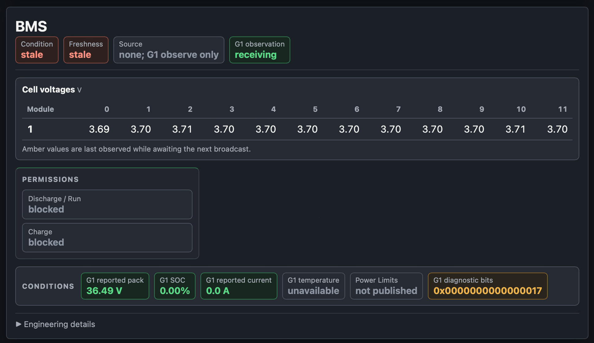
I only have one battery module connected at the moment, so 12 cells of about 3.7V, totalling 44-ish volts.
As I sit here on Friday night, I have the BMS plumbed into the code, reading cell voltages and feeding all that back into the diagnostic web interface. But for some reason the BMS seems to think 12 x 3.7 is 36V, not 44V! Grrr!
And that’s what I’ve been up to this week.

Leave a Comment