

Well, after lighting the AI blue touch paper yesterday, today’s update is back to more physical things. Chunky High Voltage connectors.
My EV will have two high voltage regimes… a low-side and a high-side. The LS connects to the battery and has a 260V connection, while the HS is a more exciting 800V. The Traction DC to DC (TDCDC) converts backwards and forwards between the two as needed.
Now some physics… apart from some losses in the TDCDC, the power going in is the same as the power coming out. And power is Volts times Amps. Therefore LS is low voltage and high current while the HS is the opposite, high voltage, low current.
High and low are relative terms here. The voltages and currents in both cases are high by domestic standards and both are very dangerous!
And even though I’m only working on my bench at low-ish powers, the kit I have is expecting all those thick cables, and that needs some pretty heavy-duty connectors.
I was tempted to just stuff some smaller cables into the TDCDC and inverter but in the end I decided that was too risky, and so I was going to have to use the proper connectors.
The TDCDC connections are simple, they are just 8mm lugs and so I can make those up with my hand-hydraulic crimper. There’s lots of cutting of insulation and peeling back of shielding, but they’re not too tricky to put together.
The real problems are the Amphenol Powerlok connectors. They’re serious bits of kit and cost well over £100 a connector. Unfortunately, once assembled, they’re not something I know how to dismantle and reuse. So I was going to have to dump a few hundred quid just to connect up my bench.
But they’re also a bit of a conundrum to assemble. Here’s all the bits for the two-terminal connector.
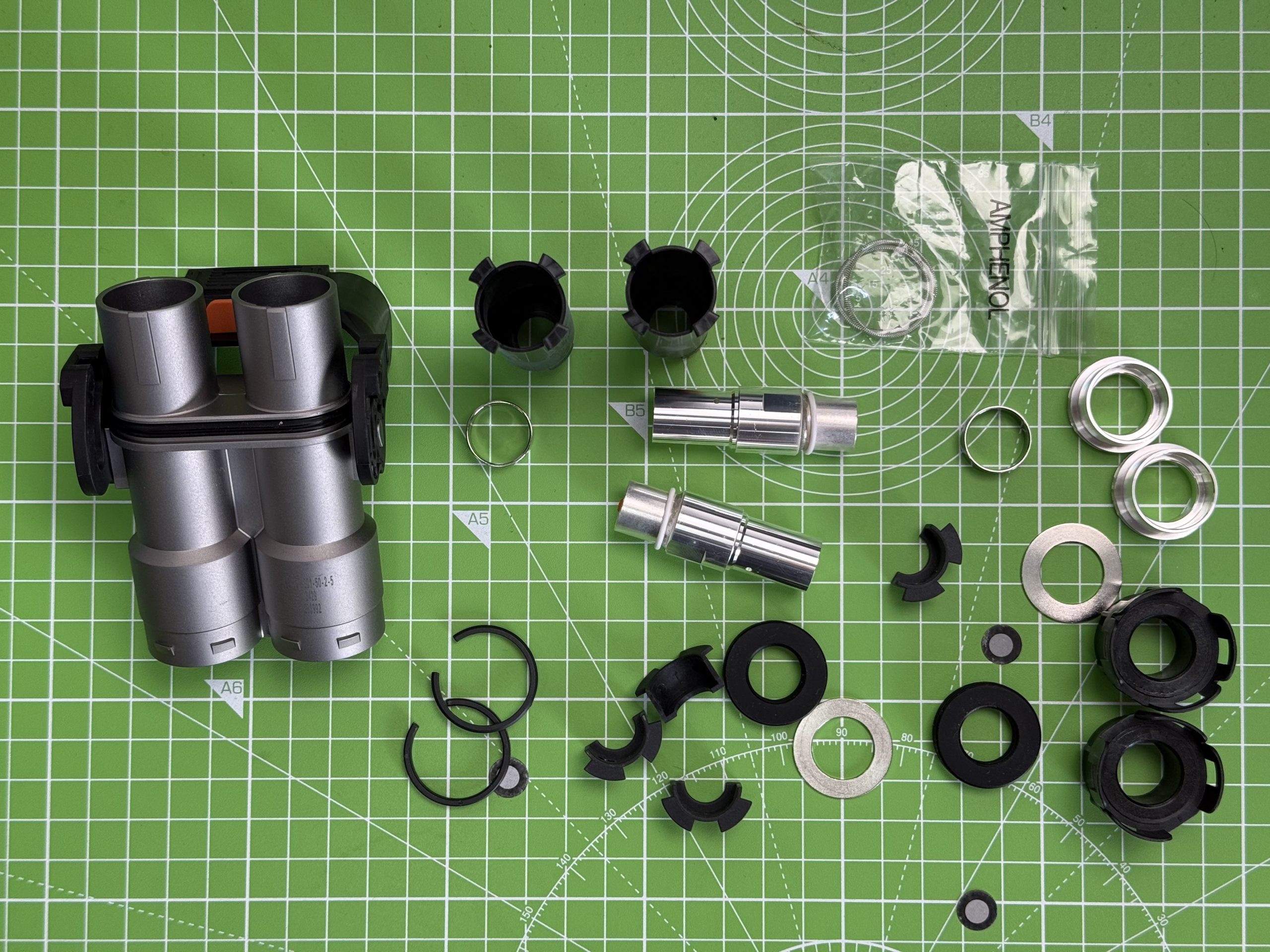
The next problem was that I couldn’t find the correct assembly guide. There’s a lot of bits and pieces, they don’t come in the package in the order that you’re supposed to assemble them, and finding the guide proved to be a nightmare.
I ended up installing the inverter DC connection by hacking it together with a 3D printed ferrule I designed. I just couldn’t figure out how they all went together and I just kludged something as best I could.
Then it came to the inverter to motor 3-phase AC connector. Helix had supplied me with some 1m “tails” already set up with the motor connections, but that also meant I had some 50 mm² cables that I needed to use (yes that’s a lot of copper in a cable, and they’re actually the smallest ones I’ll need). This is an 800V connection, so you’ve got to be careful about arcing etc. So I couldn’t just knock something up.
After half a dozen search attempts, over a few weeks, I finally found the correct assembly manual. All the websites that you can buy the connectors from (and the one I bought my connectors from) had an out of date assembly manual that didn’t give me any clues about how to assemble the new ones.
But I did find it in the end. And they’re multilingual brain-teasers in themselves…
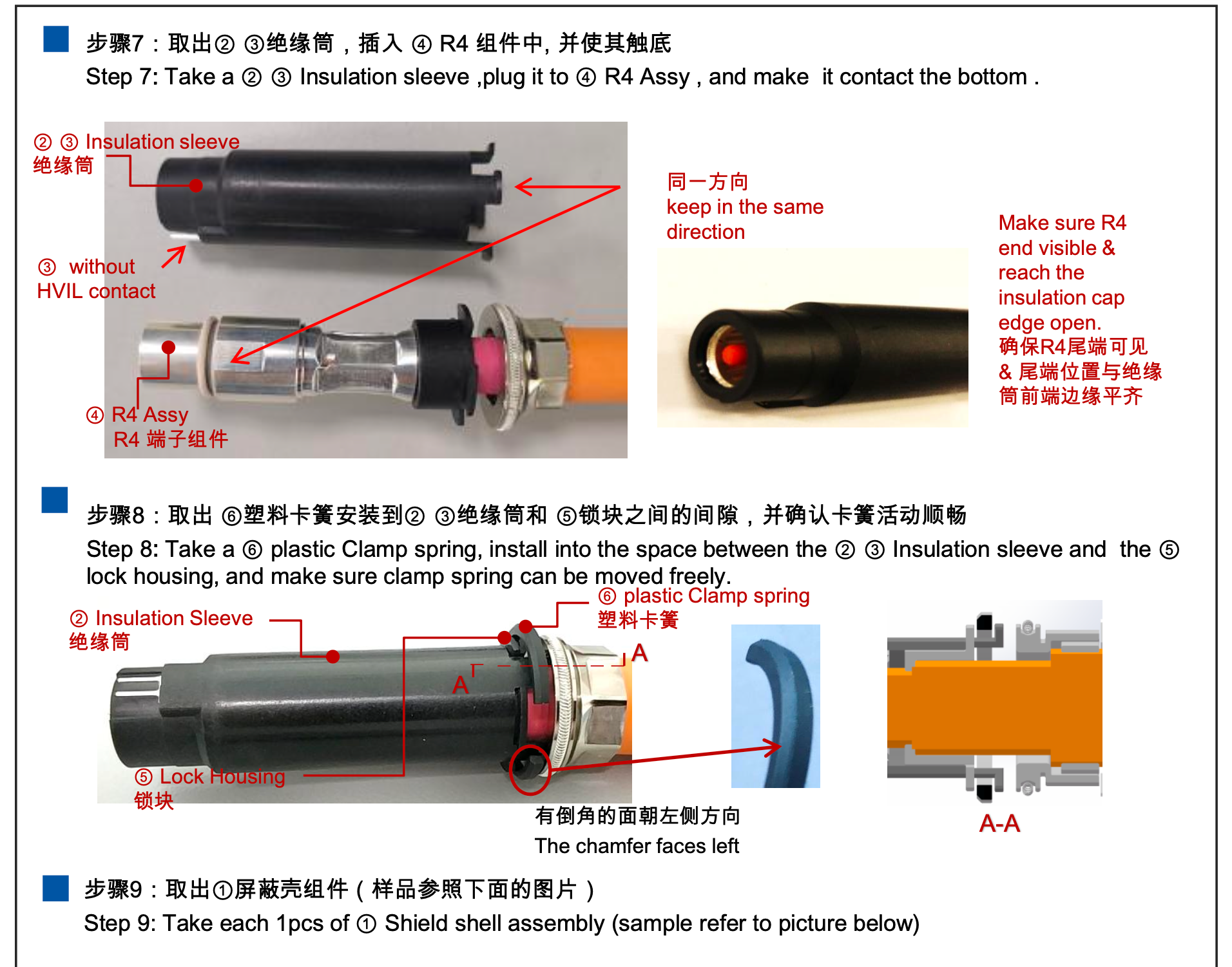
And that made it all clear, about what order to assemble all the bits and pieces. And because of the high voltages I decided the only way to do it safely was to do it as per the assembly guide.
The next problem was that my hand hydraulic crimper didn’t have a big enough set of jaws to deal with the large shield ferrule.
I needed to clamp this so there was a good electrical connection to the shield.
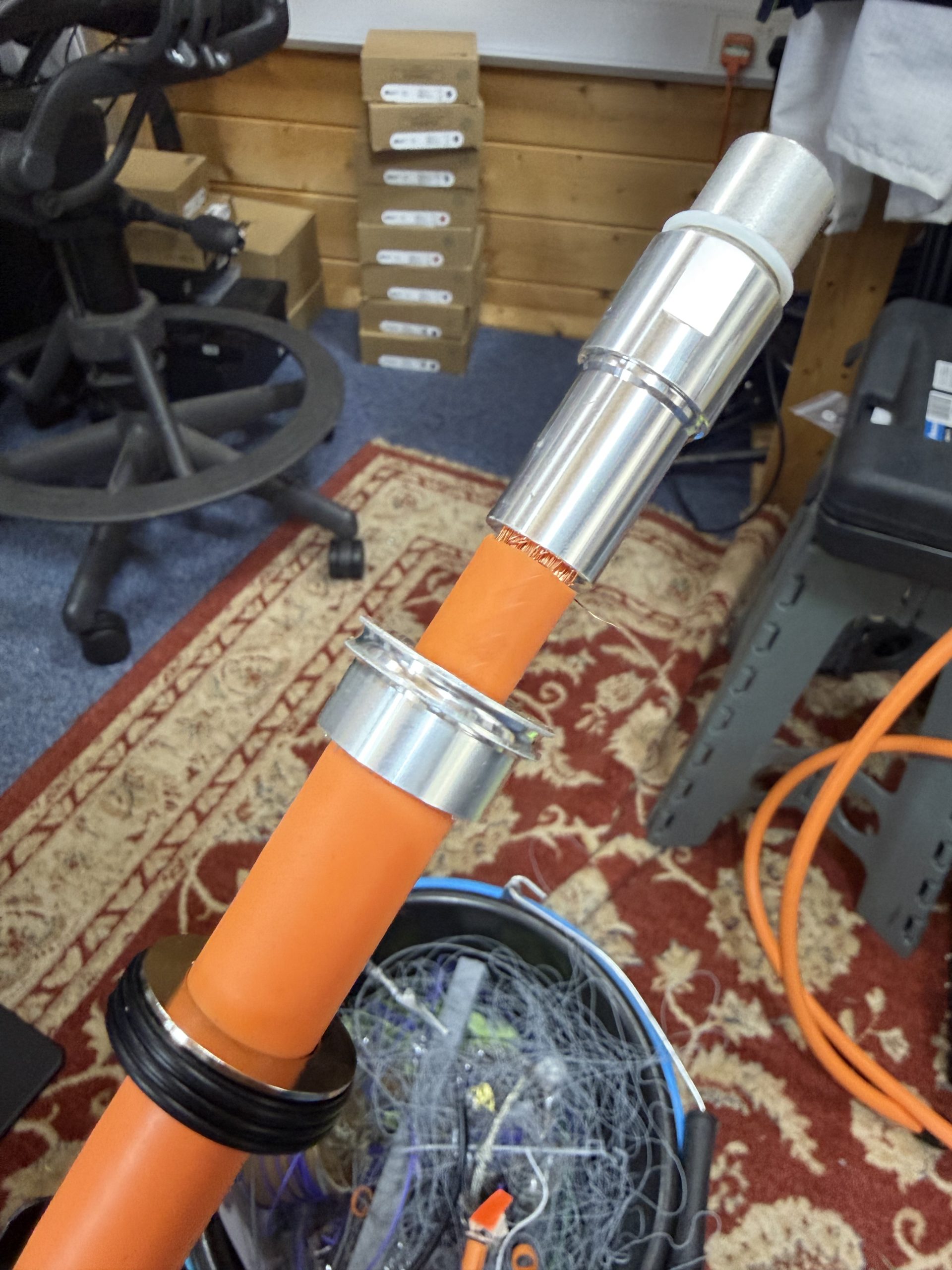
There are definitely bits of kit out there that will clamp these ferrule sizes. But they stretched into the hundreds of pounds and the really proper kit was thousands.
And that was where I had the brainwave. I could buy the jaws for about a hundred quid and make my own clamp.
The idea was to use a bench vice to provide the clamping power, the jaws would crush the ferrule into the right shape, but I needed a guide.
So I designed a 3D printed guide system to enclose the jaws, sit in my vice and allow a crimp. I could also design the guide so the ferrule sat in exactly the right place and the crush would happen just where I wanted it.
Here’s the video of the 3D design working in CAD.
And here’s the contraption working.
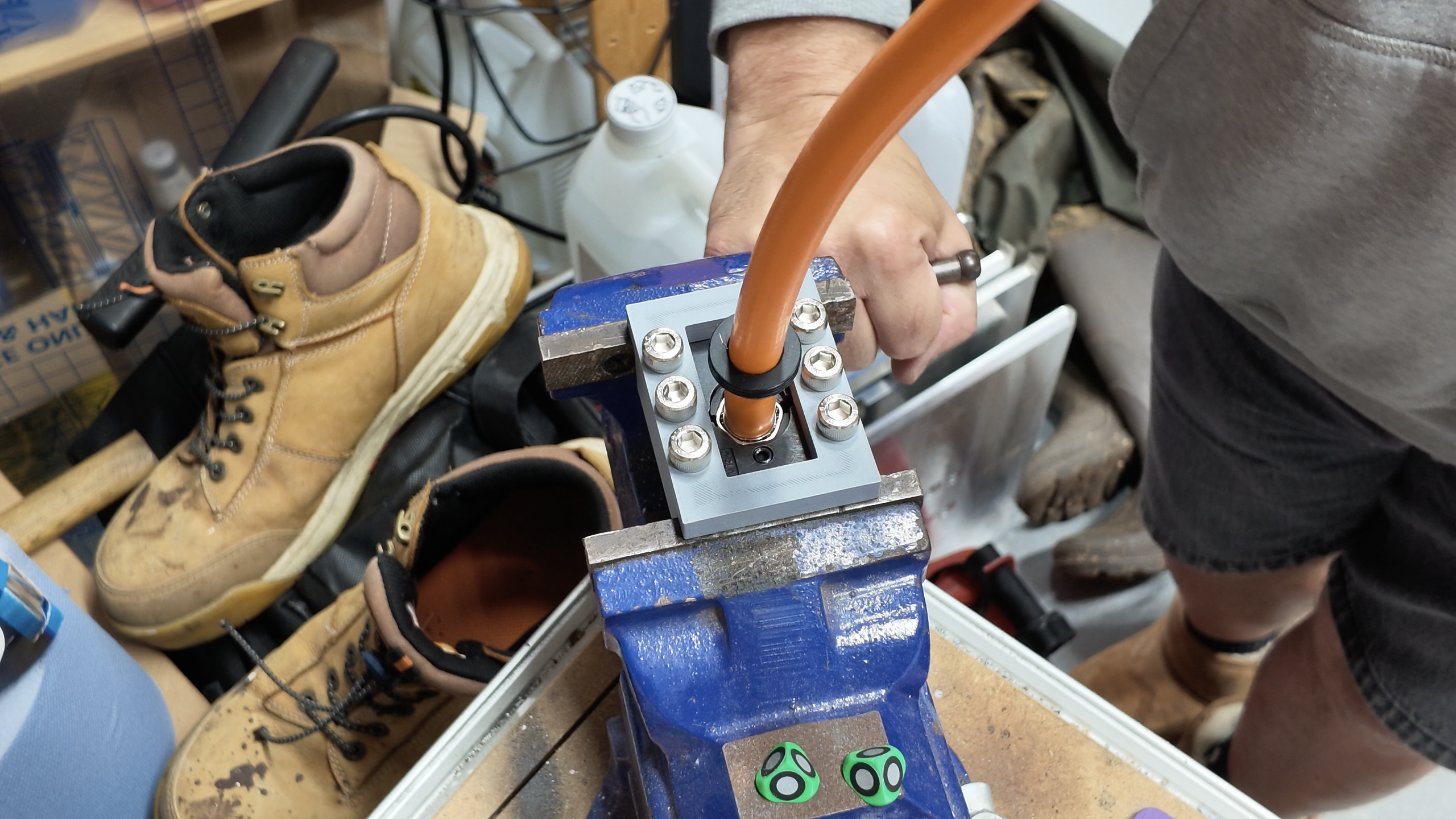
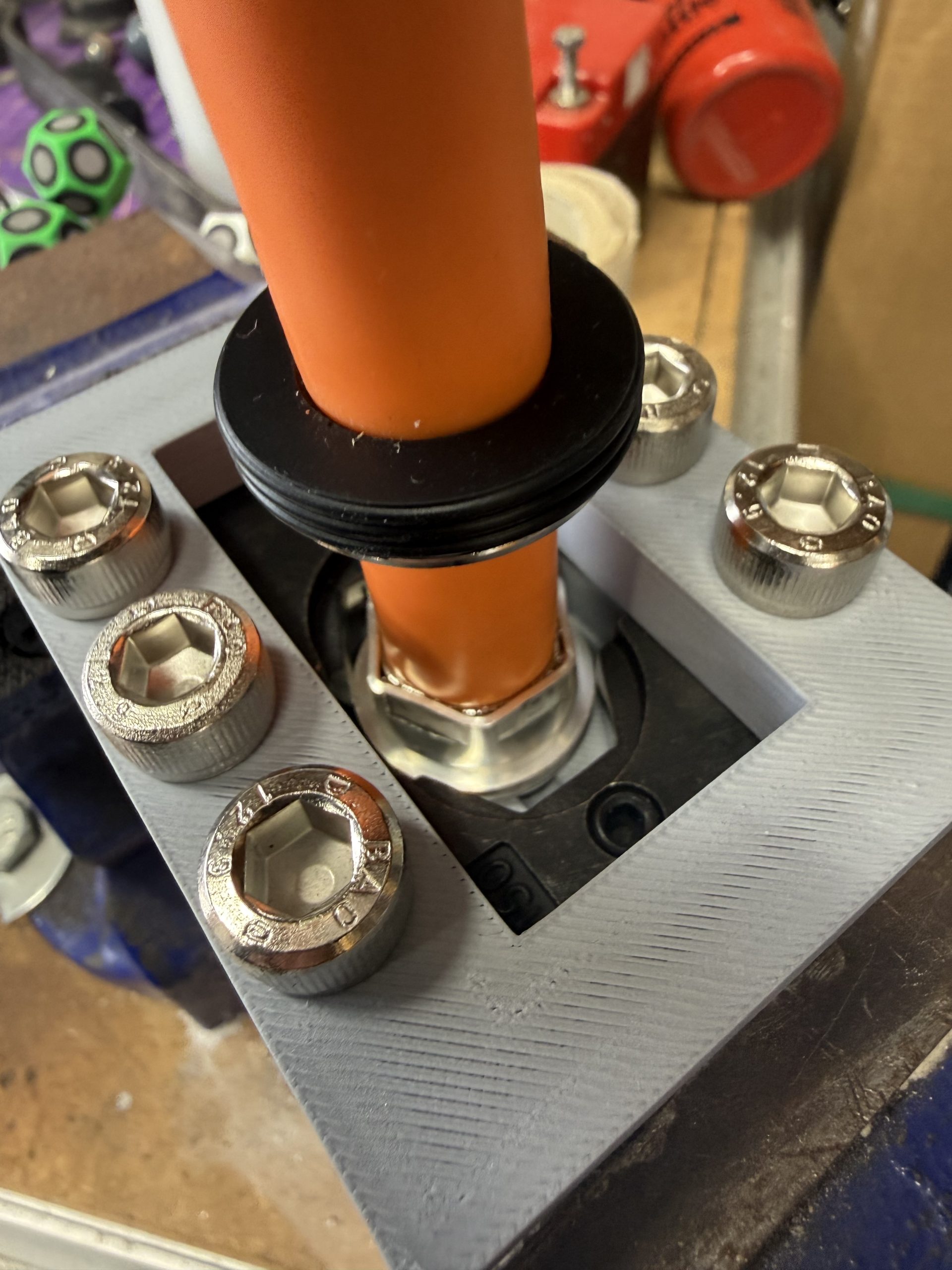
It was then just a case of crimping up all the other bits and pieces and assembling the connectors. Once assembled, there are non-return latches inside that I currently have no idea how to release.
And that was about 3 weeks of thinking, tinkering, CAD’ing and assembling. When you’re mucking about with £100+ connectors I didn’t want to just trash a few to figure out how they worked. It all had to be very deliberate and considered.
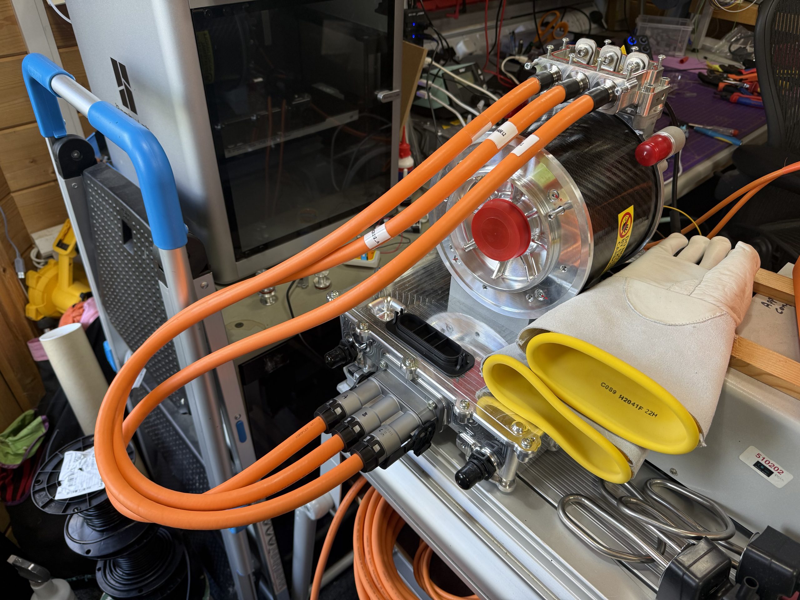
But I got there in the end. Here’s the three-way connector from the inverter to the motor…

Leave a Comment