

Ok, so we had a practical update yesterday, back to the AI today.
And if you haven’t been following… AI IS BONKERS!
I know a lot of you only skim these posts (don’t blame you) so I’ll cut to the chase. I got AI to create a printed circuit board, from scratch, with just text prompt input from me and I got it made in China and sent to me within 2 weeks! And it WORKED FIRST TIME!
So for those of you that do read the drivel I write…
As some of you will remember, I’ve got some history with CANbus. I wrote a couple of articles for LowFlying in 2019 about the OBD port on a Duratec Seven. CANbus is the name of the signalling that goes through the OBD port – doing engine maps and fault code reporting etc. The OBD port is the black dangly electronics-y thing under your steering column on a Seven.
Now my Project sEVen EV has got two CAN busses at the moment, and soon to be three. CAN1 connects my Vehicle Control Unit (VCU) to the Traction DC to DC converter (TDCDC), then to a Voltage and Current device (shunt) connected between the TDCDC and the battery and my Power Delivery Module (PDM). So that’s 4 devices chatting away on CAN1.
CAN2 is dedicated to the VCU talking to the inverter – two devices, but they talk at 1 megabit per second where CAN1 is half that rate.
CAN3 will be for the battery management system (BMS).
There’s about 1000 messages a second on CAN1 and about 2000 messages a second on CAN2. Each message is usually 8 bytes.
Now the VCU is connected to all these CAN busses but if the VCU were to have a problem then I’d have limited ways of knowing what happened just before the problem. If I can “capture” all the messages on the CAN busses, without using the VCU, then I’d have a really good idea of what the whole powertrain was doing before there were problems. The CAN busses also tell me if the various devices have faults or don’t do what I wanted them to.
Once I’ve done a test cycle on the bench powertrain, and captured all the CAN bus data, I then feed it all into another set of AIs that chop it all up and produce various reports and graphs for me.
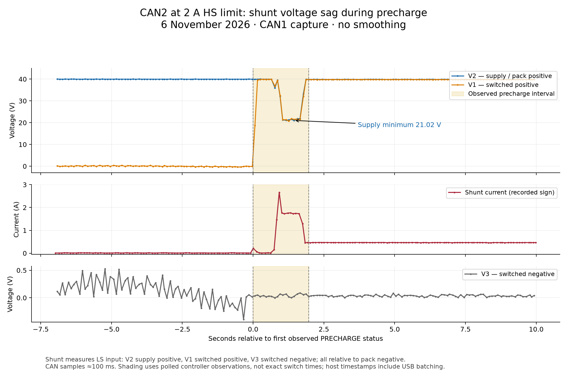
… but that’s another story.
So grabbing all the CAN bus messages on all the busses is a good idea.
And to do that I’ve created my own, what I’ll call, CAN bus Sniffer. They sniff the messages on the bus, not actively taking part on the bus but just sampling what’s going on…. sniffing.
I’ve been doing this sort of thing for about 8 or 9 years now so have gone through a few generations.
For the Project sEVen I’ve recently been using a “stack” of boards on each CANbus.
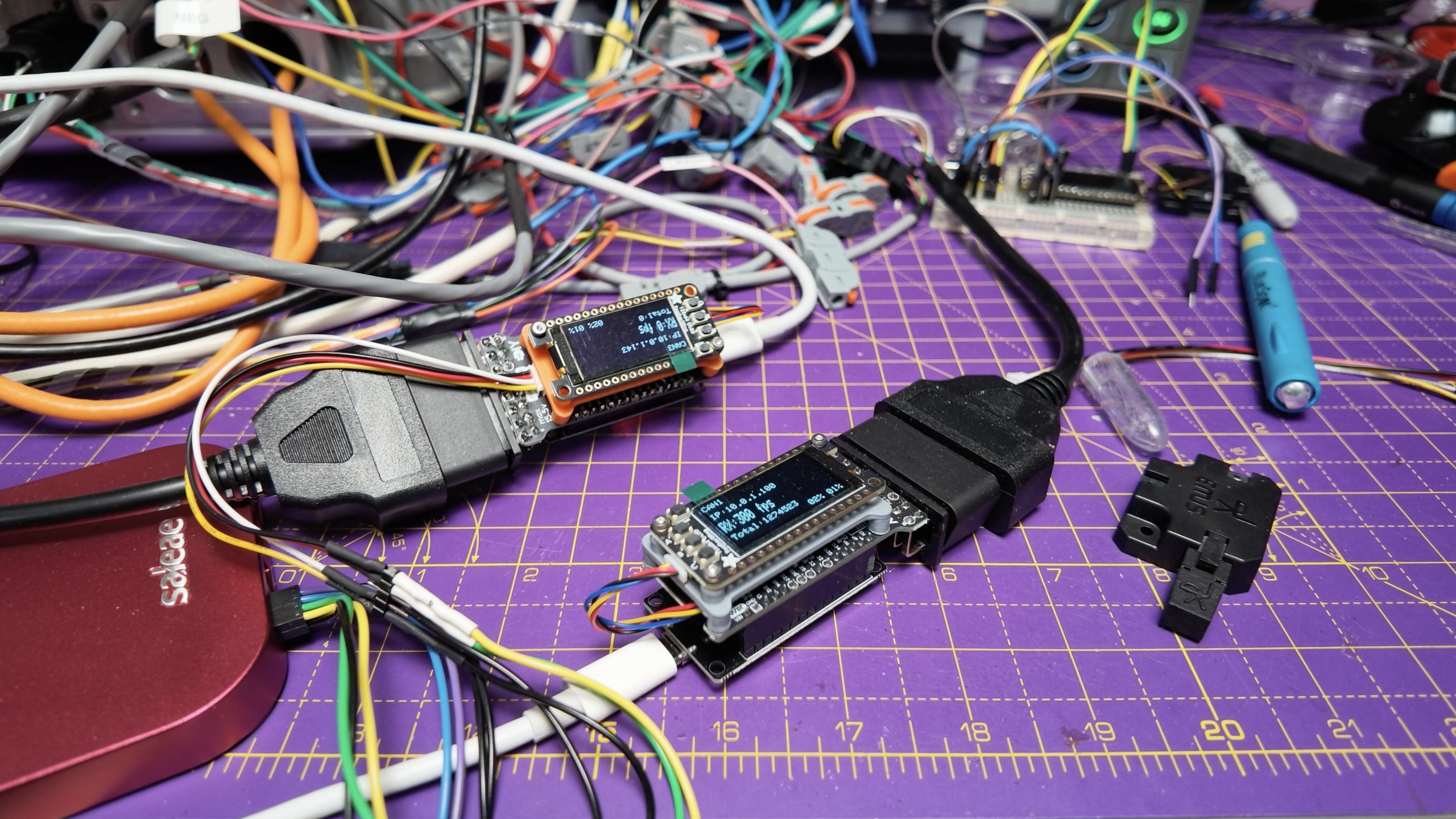
There’s a processor board (in the middle of the stack, doing all the smarts and connecting to my computers), an OLED display (giving me an instant view of whether the bus is active) and a CAN bus interface at the bottom and connecting to an OBD connector. The CANbus interfaces I’ve been using are from MrDIY.ca. The guy behind the project is very friendly and I’ve ordered half a dozen of his boards from him.
So this stack has been running for a few months. As standard you’re supposed to download some open source code to run on the processor, but I needed some extra functions… (you guessed it) so I pointed ChatGPT at it and it rewrote the firmware and that’s what I’ve used over the summer.
But, the processor in the stack (an ESP32-C6 if you’re nerdy in that way) was having problems talking to my Macs. I tried 4 or 5 different variants of the processor board that fitted the MrDIY boards, but they all had communications problems with my Macs. Every few hundred thousand CAN bus frames the interface between the stack of boards and my Mac would corrupt a captured packet. I tried all sorts of stuff to fix it and the problem would change shape but it wouldn’t go away.
What did fix the problem was going for an ESP32 processor board that has a “native” USB interface – if you know, you know. But the ESP32 processors with a native interface did not fit on the MrDIY CANbus boards… they physically were different sizes.
And that was where I got to until about 3 weeks ago.
Every time I tested the powertrain I would lose a few CAN bus packets that I didn’t capture properly and I would have to guess whether they might have contained a problem. By the laws of averages they didn’t, but it was still bugging me.
What I’d been thinking for a few weeks was that I really needed a bespoke adapter board that would connect the “native” ESP32 processor board to the OLED and the MrDIY CAN bus interface.
Then, of course, it dawned on me… AI.
I’d seen a couple of YouTube videos where people had got AI to do some stuff that was close to what I wanted but not quite the same.
So one afternoon I sat down with ChatGPT in front of me and came up with a simple prompt..
“Here’s the three boards I want to connect together. Here’s what I want them to do. Here’s the sort of size of board I’d like. And here’s how I’d like to get it made (PCBWay in China). “
The AI went to work and first designed a Schematic to do what I wanted. It then went and designed the PCB to do it. It used an open source program called KiCad. I’ve never used KiCad before and it still bemuses me how some of it works.
BUT, the AI just went and used KiCad. It figured out what connections I needed between the three boards. It went to the PCBWay website and found out what thickness of signal lines and how far each can be apart (known as the track and gap) etc. (It worked out all the design rules it needed to work to.) It worked out all the interconnects between layers (I wanted a 4 layer board).
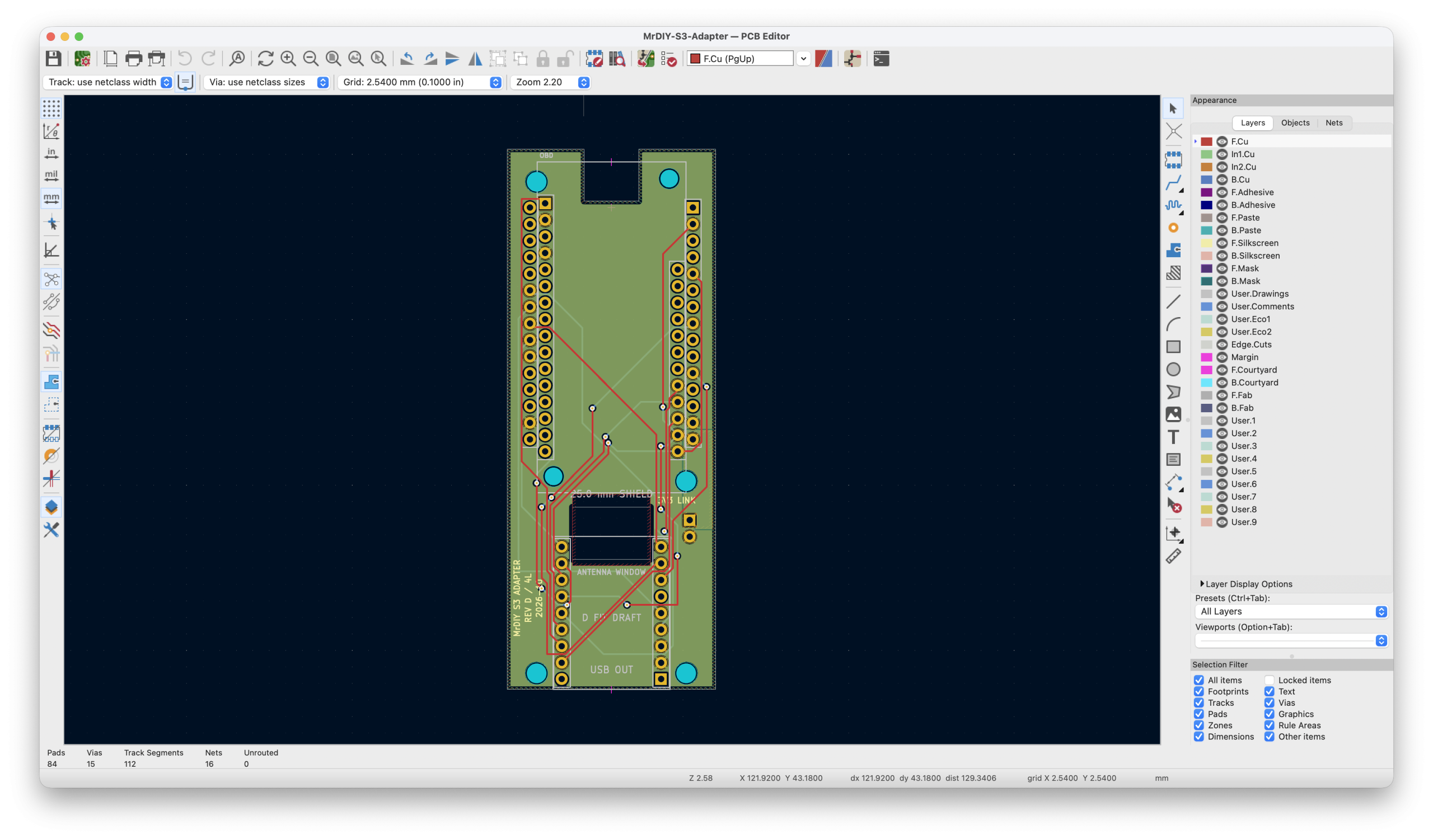
And then it gave me a zip file containing all the files I needed to send to PCBWay to get the board manufactured.
Oh… and it also made me a prototype board… a 3D model of the board that I could 3D print and test all the components fitted in the right place before I ordered the boards from PCBWay!
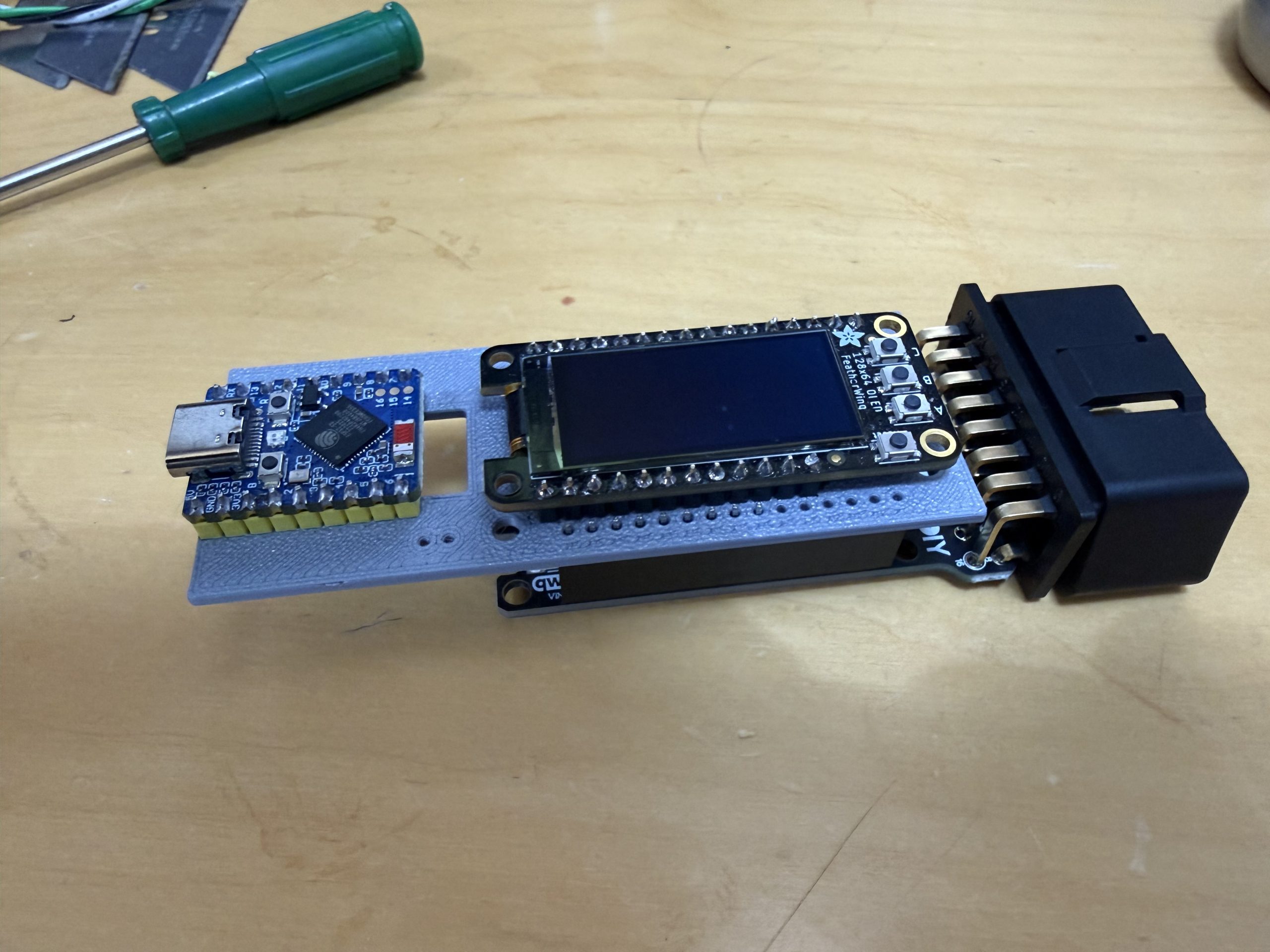
Now, I have to admit a bit of prior art. I do have a degree in electronics and for a few years (about 30 years ago) I did make a living designing up to 16 layer printed circuit boards. So could I have gone and done this myself… for sure.
Did I want to, no.
It would have taken me a week or so and it would have been a diversion. This was an interesting little project, but it wasn’t something I wanted to spend a week on.
But with ChatGPT, and me checking its output, suggesting a few changes, and giving it the right starting prompt, it was able to design me a board in about 2 hours. I spent about an hour of that time talking to it and the rest of the time it was working by itself.
I then decided I should test out what it was suggesting. So… I breadboarded the three boards together to make sure I wasn’t going to waste some money (and time) sending off what ChatGPT had created.
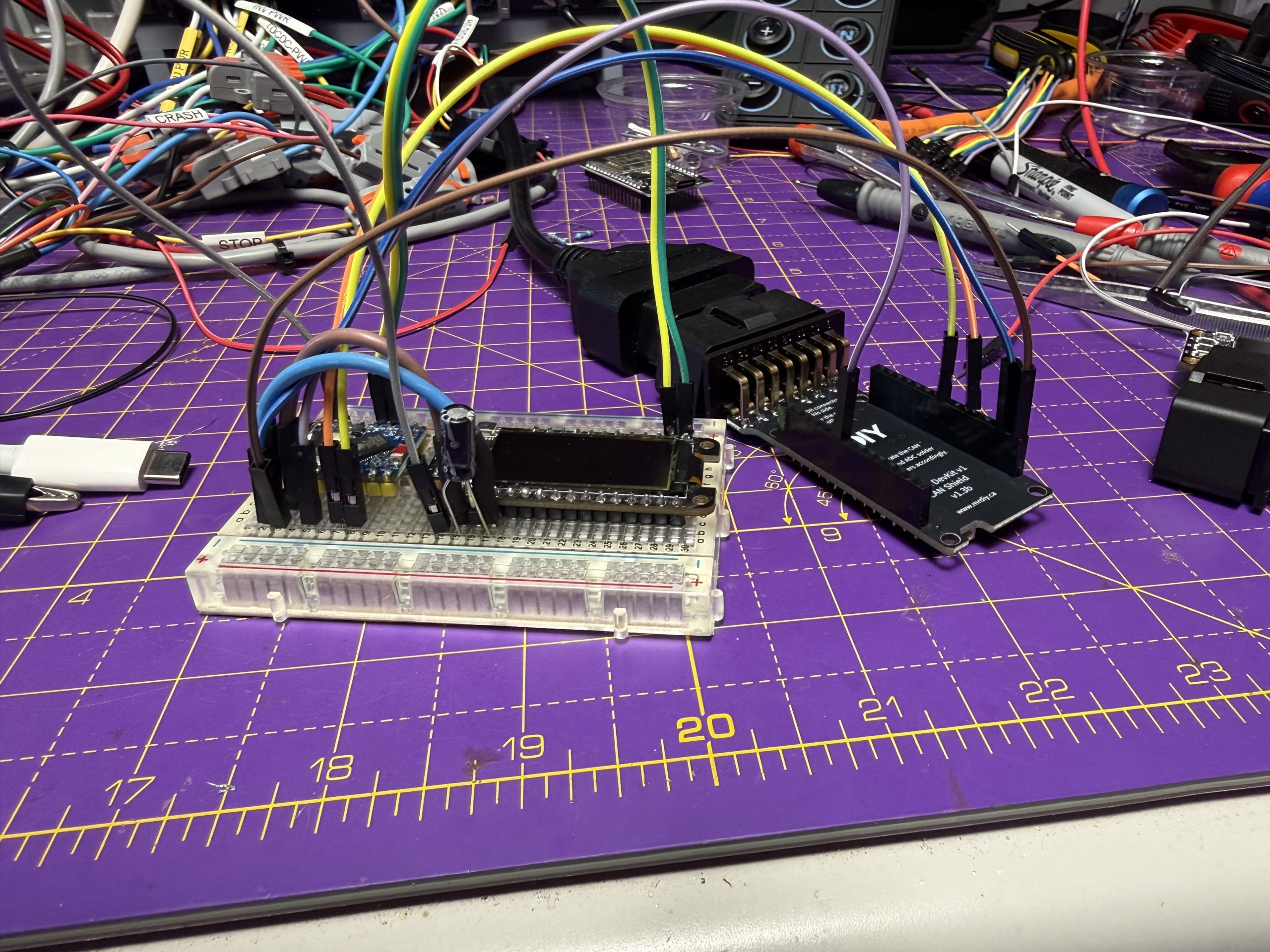
I mostly got the breadboard working, but it was enough to prove that my idle banter with ChatGPT wasn’t going to be a waste of money.
So, I hit the send button, paid the $60 on my debit card and sat back to wait for PCBWay to make my PCB.
And two weeks later I got a package in the post. 6 shiny new PCBs. This morning in fact.
I did the usual power and ground tests. Made sure the three boards physically fitted where they should do. And crucially that each board wasn’t reversed or backwards. This is a common PCB problem, you don’t realise that the documentation you’ve been using for a component is viewed from the other side from what you thought, and you end up with a PCB that needs a mirrored version of your component on it.
But amazingly it all seemed to pass muster. So I built up the boards and plugged each board in, in turn so I only blew one board up and not all three.
AND IT WORKED!
FIRST TIME!
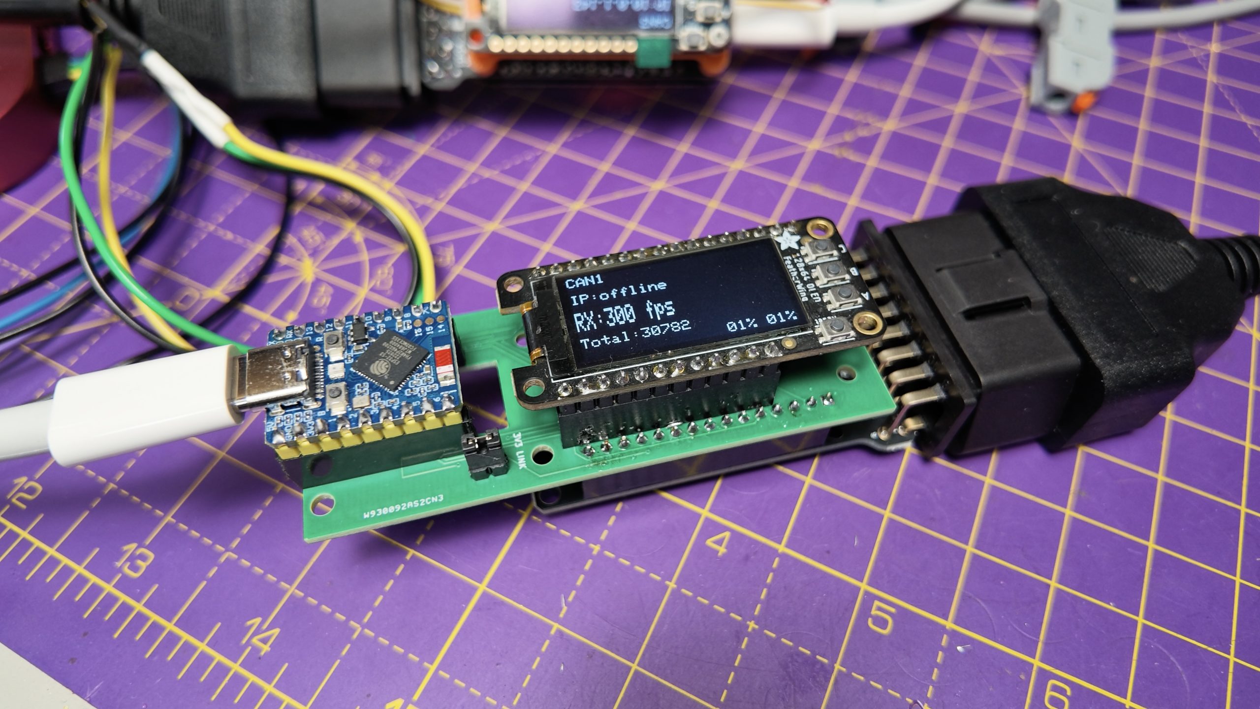
I’ve done dozens of printed circuit boards over the years. And you often have to do a version 2 or 3 or 4, because you’ve cocked up on something in version 1. But no, this thing worked first time!
ChatGPT had taken a bunch of web links, a bit of guidance from me and made a Printed Circuit Board all by itself. If you’ve made circuit boards in the past then you’re probably picking yourself up off the floor. I was!
So I’ve been running the boards this afternoon (they only arrived this morning) and they’re perfect. I’ve captured millions of CAN bus packets this afternoon, and not a single packet corrupted.
Great use of AI!
This wasn’t a critical or core part of my EV project. But it will make my life a lot easier as I go forwards. I wouldn’t have wanted to get diverted by it if I’d had to design the PCB myself, but doing it with AI was absolutely a game changer. It was at least 10 times faster than I could have done it, AND it did a better job than I would have done! It suggested a few things that I wouldn’t have thought about. I absolutely knew about those things, but I wouldn’t have thought to do them.
So, job well done!
BONKERS!

Leave a Comment