

After a couple of AI heavy updates, here’s a nice physical practical one. As I was getting ready to make the motor turn I was starting to get concerned about whether it would take off from my bench or not. I clearly needed to bolt it down, but what constituted “reasonable” when I had to explain to my wife why my office had got a big hole in the side.
The forces involved shouldn’t be large. Initially I was targeting zero torque and even after commanding it to “not-stand-still” I was looking at torque of no more than 5Nm (it can do 200Nm if I can chuck hundreds of amps at it).
But as some of you may remember, I’ve been worried about even a few Nm and an unloaded motor. It could really rip. With the mass of the rotor and even just a few Nm, it could be doing hundreds of RPM in less than a second. I could put the motor in SpeedControl mode but that’s not the intended use case and I wasn’t feeling that paranoid.
But I did need to bolt it down.
The first attempt was, shall we say, basic.
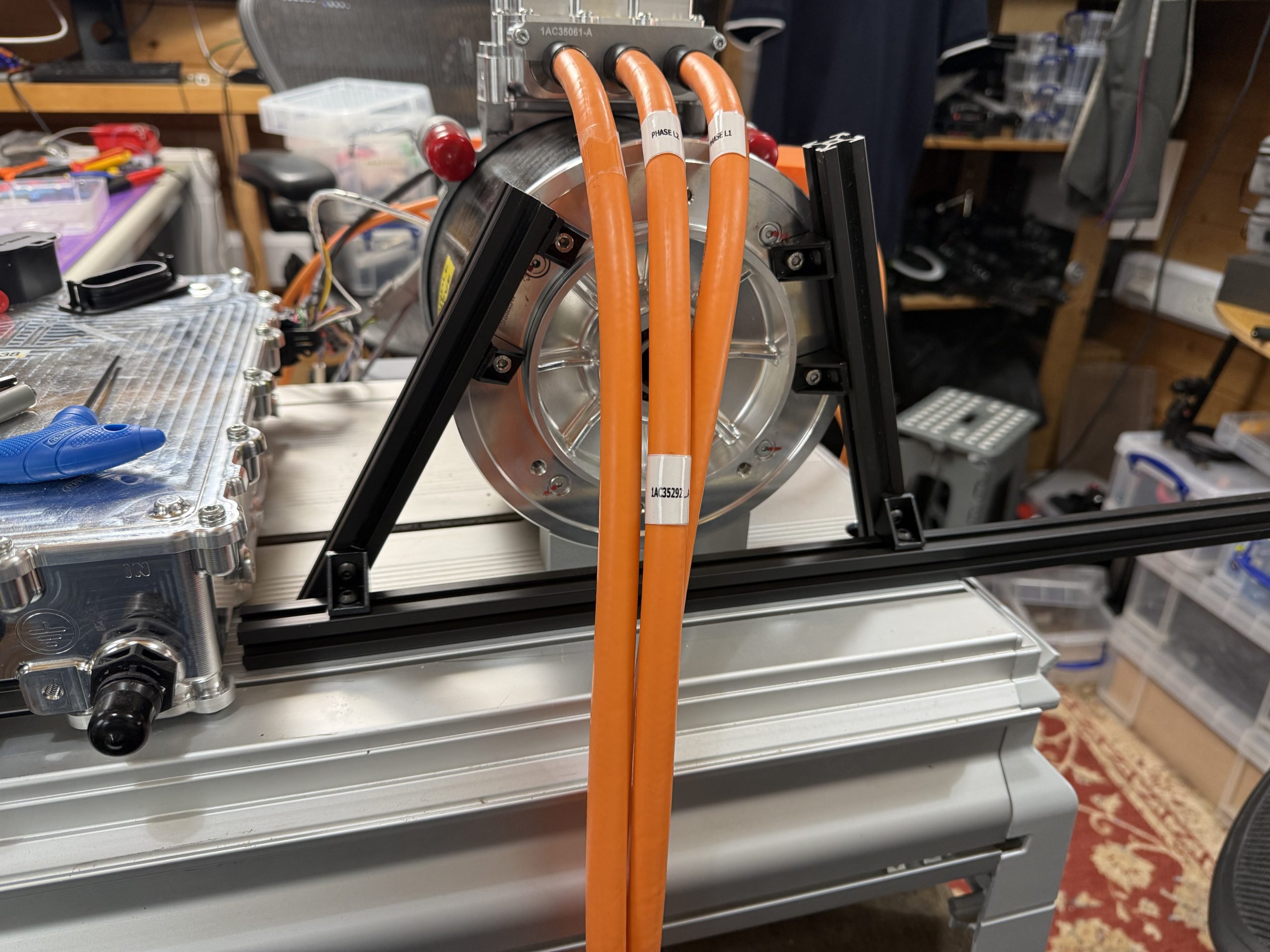
Now, in my defence, I am running a bench power supply that feeds the High Voltage system. And it limits at 3A, 40V. But that’s still 120W. I also have a Miniature Circuit Breaker in the Low Side, High Voltage path set at 6A. So there’s belt and braces, even if they’re different sizes. AND the traction DC converter (TDCDC) is set to current limit at its minimum on the High Side, which is 2A. BUT at the 350V that the High Side is set to, that’s 700W… way above what the low side is able to limit at and if I could deliver 700W into the motor then that would get it spinning very quickly!
So, my 20mm extruded aluminium rig would “probably” have been enough, but somehow it just didn’t feel solid enough.
And the reason I’m being so paranoid-ish, is that this is all software controlled. And with best-laid-plans and all that, me and my AI mate may not have got the recipe right. We might have a sign wrong or a decimal point in the wrong place. And what we think is 0Nm could be full chat 200Nm. And even if that is all current limited all over the place, it could still surprise the hell out of me.
Which led me down a garden path (literally and figuratively), and I went and bought some 10mm ally sheet, and some 50mm x 50mm x 8mm angle. As long as I can bolt it to something reasonably solid then hopefully that will be enough to stop it going for a walk off my bench.
And of course… because I can… I created a 3D printed template of the cutouts and drill positions I needed.
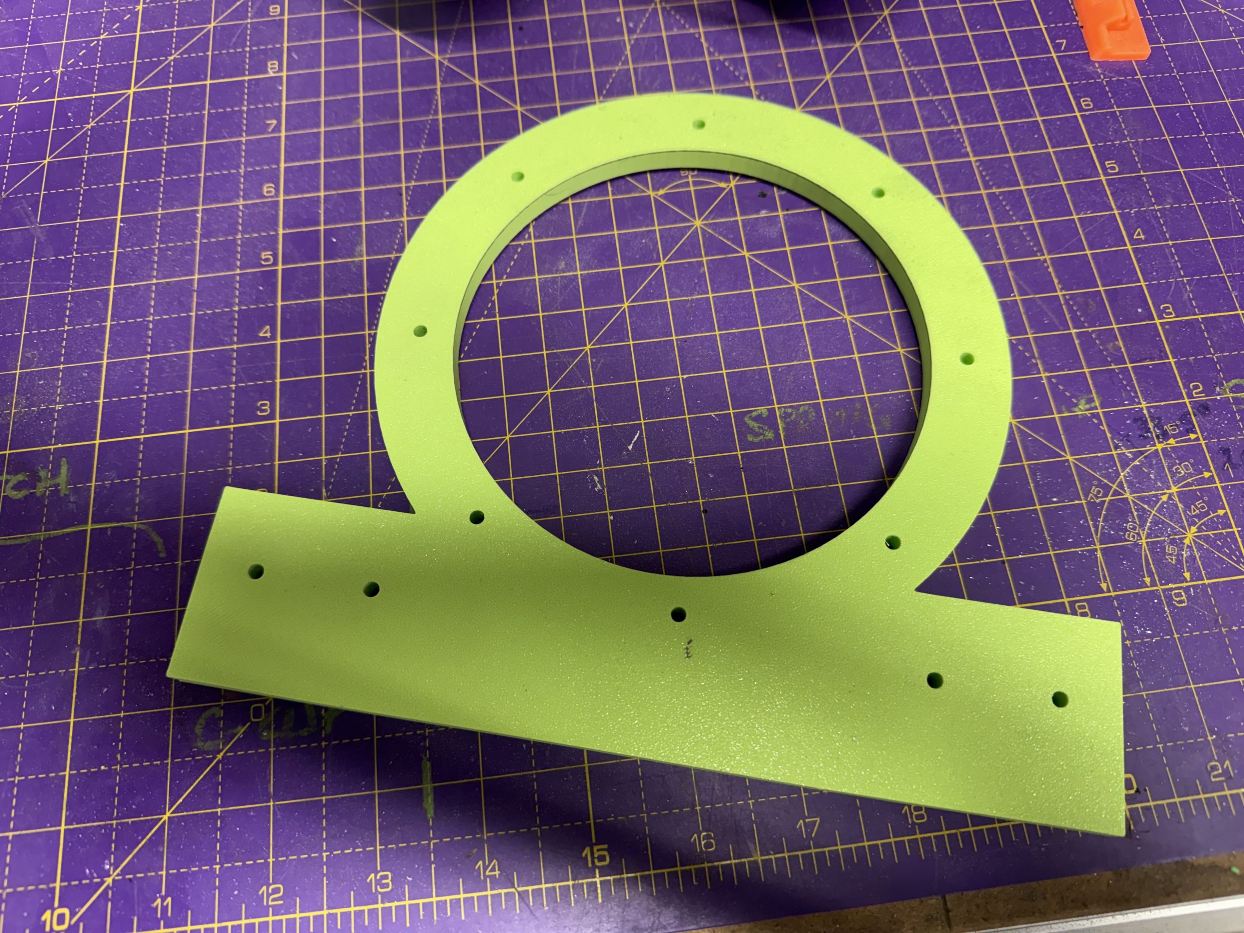
I was going to route out the big hole in the middle for the motor shaft opening but in the end I just MacGyvered it and used a jig saw to cut out a “circle” – it was not far off a circle but I’d left a couple of mm clearance so all was good.
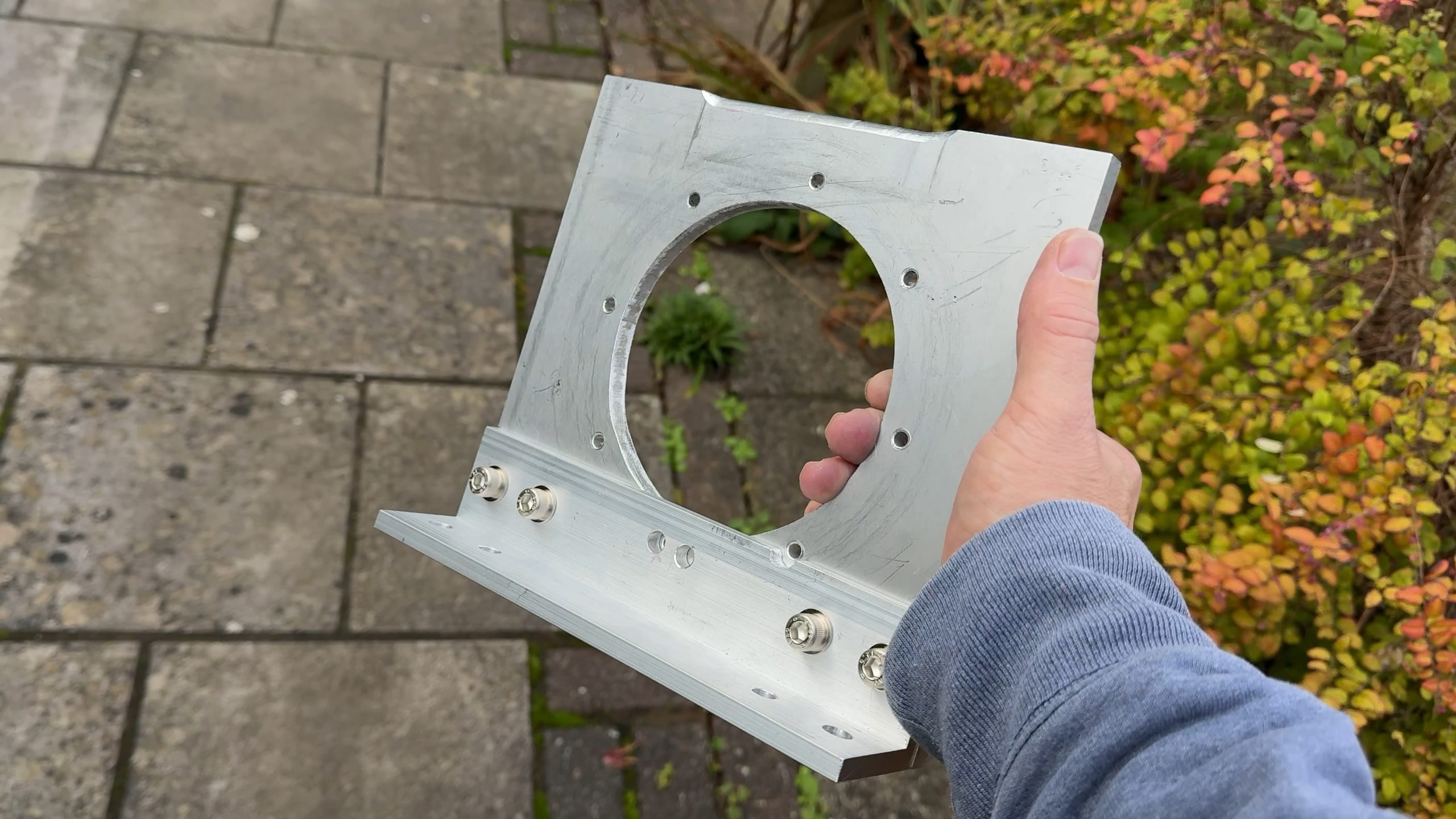
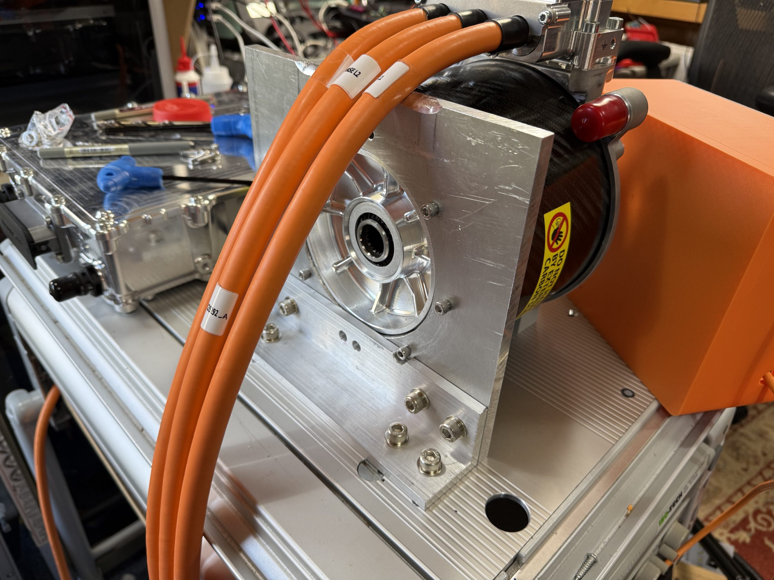
In the end I think it should be fine. But you are very welcome to come and bring grapes to the hospital if that turns out to be totally not what happened. I’m currently running down a rabbit hole trying to replace the HV bench power supply, so it’ll be a few weeks before I try and command any motor torque… but I’m now fully prepared!

Leave a Comment