

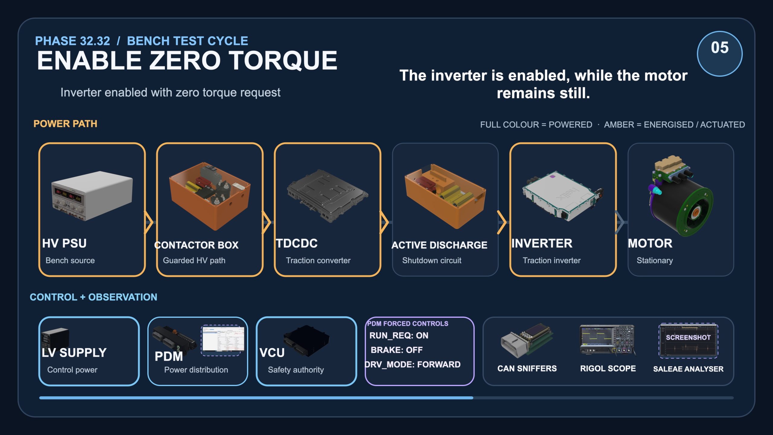
As promised, here’s another update… this time about the Bench.
After yesterday’s gearbox update the next biggest topic is probably how the testing’s going. As you probably all know I have a bench setup in my garden office where I do all the software work and try to get my drivetrain working.
The last update I did on YouTube was all about how I was using AI to develop the Vehicle Control Unit code (firmware). And that’s pretty much what I’ve been doing for the past few months. At the point of that video I’d got about 2/3 of the drivetrain working and was looking at hooking up the inverter and motor.
Well I got both of those connected – after a bit of a struggle (more about that in a future post). At about every stage something didn’t quite work the way I thought it would and I had to backtrack and change my approach. I’ve put together a quick update video that I’ll link to below. And that in itself is a story – because I’ve had AI so intertwined with my project, I could just ask AI to create me a video about the state of the workbench. And this is what it came up with. I had to feed it some images and tweaked it over a few iterations, but the video is essentially all edited with AI. That would have taken me a week to have done by myself and AI did it over the course of about 24 hours as I poked it from time to time. At some point I might put a voice over to it along with more of an update and make it live on YouTube, but for the moment it’s an unlisted video, so you’ll only find it from the link below.
And the AI has been really busy on not just the software but the testing too. For quite a few weeks I was getting my AI to run all the bench testing. It would communicate with my power supplies, oscilloscopes, logic analysers etc and would orchestrate a test run – firing up the bench, precharging the power train, initiating the inverter and then tearing the whole test down again.
[ for some of you that are AI nerds, this was mostly done with MCP connections to the various software apps and hardware ]
It would then capture all the waveforms from the equipment, analyse the CANbus captures (I have two CAN busses at the moment – soon to be three). It would then correlate all the captures along with the logs from the Vehicle Control Unit and tell me where there were errors or timing issues. The whole thing was automated through AI. It could then draw me plots of things like current and voltage, pre-charge rise times, CANbus transaction ladder diagrams etc etc.
But I was finding that the AI wasn’t thinking quickly enough. It would take a couple of minutes to run through all its machinations to make a bench test cycle happen. The result was, frankly, incredible, but it took a bit of time.
So now I do things a little differently. The AI still changes the code, adds new features and analyses all the results from a test run. But the actual test run is orchestrated by a Python script. I run the script from a terminal and it guides me through the test run. It asks me to press the brake pedal, or the throttle or turn the ignition on. Those are things I haven’t automated (yet). But the Python script will run through a test cycle in 30 seconds rather than 2 minutes that the AI took. The AI still analyses all the results but it’s dropped my testing time considerably. I show a bit of that in the video.
The bench has got to the point where I can power up all the drivetrain (precharge etc) then set it so it’s just ready to turn the motor. BUT, my bench power supply that I’m using to replace the VW battery modules, hasn’t got enough oomph to turn the motor. It current limits during precharge, and wouldn’t be up to turning the motor. So, I need to replace it with a real battery module. And that means I really need to get the Battery Management System running. It’s very tempting just to see if the bench power supply will turn the motor, but I really really really don’t want to cause damage by a bunch of very expensive components being current limited and getting damaged – they could go into a shutdown mode and one of them doing that could cause problems for another device and damage that. So I don’t want to do that.
The bench supply I’m using as a surrogate battery also can’t sink (receive) current. So if the motor were to get moving a bit too quickly and then I shut things off, the back emf of the motor could induce quite a high reverse current that could blow up my power supply. I really really don’t want that to happen either.
So all in all I think it’s better that I take things slowly and hook up a battery module correctly. And that’s a whole bunch of new code and a lot of testing, just to get back to where I’m ready to turn the motor again.
Better safe than sorry though.
Here’s the link to the update video. Hopefully it makes sense. Sorry it’s a bit long, but it’s a complicated system and if I skim over stuff then it’ll be completely unintelligible to everyone.
Any questions then let me know.

Leave a Comment