

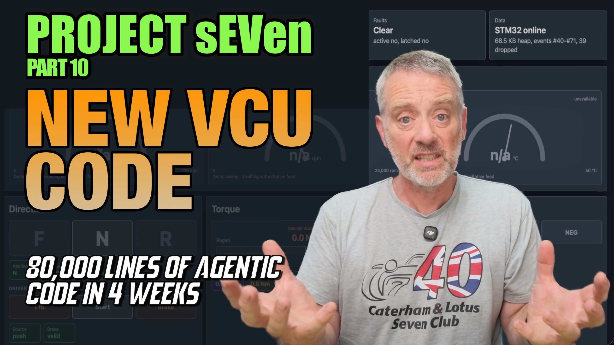
New video: July EV bench update
New video covering the latest progress on my Caterham Seven EV conversion.
Over the past four weeks, I’ve rebuilt the vehicle-control software from a clean sheet. The new system runs across the STM32-based ZombieVerter VCU and an ESP32-S3 communications coprocessor.
In the video, I walk through:
- the updated test bench and contactor box;
- the IVT-S current and voltage sensor;
- the traction DC-to-DC converter producing 260 volts from the 40-volt bench supply;
- the new VCU software architecture;
- the live web-based diagnostic interface;
- ignition, precharge and drive-selection operation; and
- the command-line terminal used for detailed diagnostics.
The inverter and motor aren’t connected yet, so the torque path remains diagnostic. The next major objective is to bring up the inverter and, ultimately, get the motor spinning.
Full update here:
It may be slightly over-engineered—but that’s half the fun.
Vido transcript
The following transcript has been lightly edited for clarity. False starts and filler words have been reduced, and technical terms misheard by the automatic captioning system have been corrected.
July Bench Update — Video Transcript
This transcript has been lightly edited for clarity. False starts and filler words have been reduced, and technical names misheard by the automatic caption system have been corrected.
Introduction — 00:00
Hello everyone, and welcome to another Purple Meanie YouTube video. This is another video in my “Putting the EV in Seven” series.
When I left you a few weeks ago, I had the traction DC-to-DC converter up and running, and I had my bench test rig working. Today I want to give you an update on where I am now—which is pretty much where I was, but having done a whole bunch of extra work in the meantime.
I’m going to give you an update on the bench hardware—the ZombieVerter, traction DC-to-DC converter and all of that—and then an update on what I’ve been doing with the software. Basically, I’ve rewritten the whole thing.
We’re going to get into the weeds. I’ll show you what I’ve been doing, give you a look at the project’s new web interface, and show you the terminal that gives me command-line access to the project and lets me get lots of data out of it.
Sit back, and I hope you enjoy the video.
The bench setup — 00:59
Hopefully, as you remember from previous videos, this is my bench setup. I’ll do a very quick run-through in case you missed some of the previous material, and then I’ll cover the changes.
Starting from the battery pack: I have batteries under the desk, but they’re not being used at the moment. Instead, I have two bench power supplies acting as the battery pack. They’re running in series at 40 volts.
That feeds into a contactor box, which I’ll cover in a second. The contactor box feeds down a cable into the low-voltage side of the big grey traction DC-to-DC converter. It’s capable of 250 kilowatts of DC-to-DC conversion. On the bench at the moment, it takes 40 volts from the power supplies and converts it to 260 volts on the high side, which I’m measuring over here.
That is the high-voltage path. Control comes from the ZombieVerter vehicle control unit. It is open-source hardware and was running open-source software, although we’ll come back to the software in a moment.
There’s a small coprocessor board attached to it. In my implementation, that is an ESP32-S3 dual-core processor. It has a small OLED display showing things such as the IP address it is using, so I know how to log into it.
The ZombieVerter itself uses a 32-bit STMicroelectronics STM32F107 microcontroller.
I also have a power distribution module. It sequences the low-voltage, 12-volt supplies, powers the VCU, and powers the low-voltage side of the traction DC-to-DC converter. It has a 12-button keypad programmed over the CAN bus.
The blue button is the ignition button, simulating the car’s ignition switch. There are also D, N and R buttons for drive, neutral and reverse—represented in the software as forward, neutral and reverse—and the button at the top right is Start/Stop. Once the system is in Ignition, I can press Start/Stop to energise the system.
The coprocessor board has a serial connection, alongside the programming interface for the STM32. Both run through USB and a hub to my computer.
That is the basic bench setup. Now let’s concentrate on the new things.
Bench hardware changes — 04:16
The first new item is the coprocessor board, which has a whole set of new software on it. That has changed since my last bench video.
The other major change is the contactor box. Previously, its circuit breaker was external to the box and flopping around on the bench. I also didn’t have the black device at the bottom or the cable running out of it.
The black device is an IVT-S shunt. It measures current in the negative line running through the box. It also has three voltage sensors. I’m measuring the voltage on the battery-pack side of the positive contactor, on the traction DC-to-DC side of the positive contactor, and on the traction DC-to-DC side of the negative contactor.
That is now integrated into a new box, which I 3D-printed, with a newly routed Perspex cover. The LEDs showing positive, negative and precharge activation are still working.
The other new item on the bench is a CAN sniffer. It uses a board from MrDIY.ca with an ESP32 board sandwiched in the middle and an Adafruit Feather OLED display on top. The display shows its IP address, received CAN-packet count, and the load on both processor cores.
It sends packets using the GVRET protocol back to my Mac, which I covered in a previous video.
That is the bench setup as it stands. Now let’s look at the software.
Why I rewrote the software — 06:40
Before getting into the software in detail, let’s have a quick look at why I’ve been doing this and what I’ve done.
My previous bench videos were based around the open-source ZombieVerter codebase and hardware. I’m still using the hardware, but I’ve changed the software quite a bit.
I reached a fairly good stage with the bench and the traction DC-to-DC converter, but I wasn’t confident that I was adding software in the way I wanted, or in a way that made sense for my project.
About a month ago, I decided to look at making a clean sweep. I’d been using Codex, ChatGPT’s coding agent, on about a dozen projects over the previous six months and had done lots of things with it. I had been very reluctant to use it on the vehicle control unit for this EV project, but eventually I reached the point where I felt reasonably confident and decided to have a go.
I started with a clean sheet of paper—none of the open-source ZombieVerter software and none of the previous Wi-Fi coprocessor software—and started again.
That allowed me to implement a fairly classic software architecture. Drivers sit at the lower level. Devices sit on top of those drivers and consume their data. Services sit above the devices and use their output. Above that is the application layer, which contains the vehicle finite state machine.
All of that runs on the STM32 microcontroller in the vehicle control unit on the ZombieVerter circuit board.
Alongside it is the Wi-Fi coprocessor: the ESP32 on the daughter card with the OLED attached. It connects to the STM32 VCU over a one-megabit serial link. The ESP32 is responsible for rendering a website that I can access over Wi-Fi, and for providing a terminal that gives me even greater diagnostic access to the vehicle.
That is the software architecture I’ve implemented. It will evolve as new devices, services and drivers are added, but that is where it stands today.
The new web interface — 09:12
Here we are in the web interface. It is served by the Wi-Fi coprocessor and displayed over Wi-Fi on my desktop. As you can see, there’s quite a lot going on. This is the result of about a month’s work.
There is a list of pages down the left-hand side. We’re looking at the Dashboard at the moment, and I’ll run through what the pages do.
The Dashboard shows the high-level readiness of the system and the bench. Some gauges currently run in test mode for future vehicle speed, motor RPM and battery-pack temperature.
At the bottom is the direction indicator, showing whether forward, neutral or reverse is selected. It also shows whether ignition is on, whether Start has been pressed and whether the brake is depressed. The brake is hard-wired as pressed for the bench at the moment.
There is a torque indicator showing the amount of torque being requested from the inverter. The contactor indicators show whether each contactor is open or closed. They’re all greyed out at the moment, so they’re open.
Drivers
Looking at the software model I just showed you, we’ll start with the Drivers at the lower level. Each panel represents a device driver.
There is a CAN driver; GPIO drivers; output drivers controlling the hardware outputs; and the serial-link interface between the ESP32 and the STM32 vehicle control unit. These are rendered in real time.
If I press the accelerator, the analogue-to-digital converter values change. Those values are the input to the throttle. You can also see the CAN traffic count increasing.
Devices
CAN feeds the next layer: Devices.
The power distribution module is connected over CAN. You can see the number of packets received on CAN ID 0x210, and the PDM is currently sending the forward/neutral/reverse request, which is Neutral.
The shunt provides voltage, current, power and temperature measurements over the CAN bus. It sits on top of the CAN driver and is currently showing quiescent voltages and essentially no current flow.
The Drive Selector handles the forward, neutral and reverse input. It also has the concept of freshness: the data has not gone stale and contact hasn’t been lost with the CAN source. The selection has been accepted because it is fresh and valid. More information is available under Engineering Details.
The Throttle device takes input from the lower-level ADC driver. It fuses the two ADC channels into one throttle request from zero to 100 per cent, with a dead zone. The interface shows whether the throttle is released, the two input channels and the fused percentage output.
The Traction DC-to-DC Converter is also on the CAN bus. At the moment it is in an unknown state because ignition is off and its 12-volt supply is not powered.
The inverter isn’t wired up yet, so it is unavailable. The battery management system is not connected either; a fake module currently supplies the permission needed to exercise the rest of the system. The chargers are also not connected.
Services
Above Devices are the Services.
The High Voltage Manager, or HVM, takes input from the shunt and traction DC-to-DC converter. You can see the battery-pack and low-side shunt values moving because the shunt is powered, but the HVM is Open. The contactors are open and the system has not moved through Low-Side Precharge, Low-Side Closed, HV Ready, Opening, Discharging or Fault.
There is also a Torque service. It takes the throttle output and decides whether there is a valid torque request. Inputs from the Fault Manager, BMS and other parts of the system determine whether torque is allowed to proceed to the inverter.
Other services include the Fault Manager; the Charging service, which will handle the charging modes; the Configuration service, which allows parameters to be configured; and the Dashboard Stream, with diagnostics for the web interface.
Vehicle
At the top application level is the Vehicle finite state machine. It currently shows that the vehicle is Off. Ignition is off; the system is not in Precharge, Run, Shutdown, Fault or Charge; and the page shows any faults or inhibitions present in the system.
Below that is a view of the powertrain: the battery pack, low-side precharge, low-side bus, traction DC-to-DC converter, high-side bus and inverter, which is not operational at the moment. The Drive Demand section shows the fused throttle and torque request.
That brings us back to the Dashboard.
Other pages
The Configuration page lets me set various parameters on the board. When I’m working on the bench, I don’t want to recompile everything just to change a parameter.
Signals exposes the VCU’s internal signals so I can watch them change.
CAN Mapping will eventually allow internal variables to be published on CAN IDs. At the moment it does very little and uses synthetic data.
Plot allows me to graph values such as torque requests or shunt measurements.
The Data Logger can capture selected values at various rates and export them in CSV or JSON format.
Updates provides a way to upload firmware to the board. At the moment I usually do that through the debugger.
Files lets me inspect, change, delete and upload files on the Wi-Fi coprocessor’s filesystem.
Wi-Fi lets me change access-point and station-mode settings. Audit lets me see what has been happening in the system. Faults shows latched faults or faulty devices that may inhibit the system, and Events provides a related event view.
There are also pages for the two processors. The ESP32 page shows its running tasks and CPU use. The Loop task is taking quite a lot at the moment, which I want to investigate.
The STM32 page shows its tasks and changing runtime data. Its Link task also looks a little high, and I’d like to reduce it. If the browser disconnects, that link activity drops towards zero because there is no data crossing it.
The link can operate in Balanced, Fast or Quiet mode. The software protocol between the STM32 VCU and the ESP32 Wi-Fi coprocessor uses a subscription model.
When the two processors boot, a catalogue of telemetry metadata is sent between them. That includes field names and information describing values as voltage, current, frequency and so on. After that, the telemetry itself is binary. There is no need to transfer JSON between the processors: only IDs and values are sent.
The web interface uses the catalogue to decode those values and render the site with relatively little traffic over the serial link. It is using roughly three kilobytes per second here, rising to around eight kilobytes per second. Subscriptions change according to the page being viewed, so the transferred data changes when I move to a different page. That is a very manageable load for these processors.
Finally, Web Health provides simple diagnostics about the web system.
Running the bench — 18:53
With that in mind, let’s fire up the bench and see what it looks like when it is running.
The first thing I’ll do is turn on ignition, represented here as T15. When the indicator goes green, ignition is on. I’ll go over to the bench and press the ignition button.
T15 goes green and the system starts up. On the Devices page, the traction DC-to-DC converter is now Ready rather than Off, and its low-side and high-side parameters are coming in. On the Drivers page, CAN is up and running, and the ADC is still operating. Pressing the accelerator still moves the throttle.
The next step is to precharge the low side and high side. I do that by pressing the Start button on the PDM keypad. We’ll see the positive and negative contactors perform their sequence.
I press Start, the contactors perform their dance, the positive and negative contactors close, and we have 260 volts on the output.
Looking at the Devices page, the shunt now shows 40 volts. The traction DC-to-DC converter also shows 40 volts on its low side and 260 volts on its high side. Good news.
Back on the Services page, the Torque service still cannot produce a torque request because we are not in a drive mode. Let’s do that next.
I press D on the keypad, which selects Forward in the software. Back in the Torque service, pressing the accelerator now produces an accepted torque request that would be sent to the inverter. There is no inverter connected at the moment, but that is how the path will work.
As you can see, quite a lot of the system is running, and the interface lets me debug and diagnose what is happening.
The HVM display has progressed from all contactors open, through Low-Side Precharge and Low-Side Closed, to HV Ready.
I’ll run precharge again so you can see that transition. I press Start, and the High Voltage Manager moves through its phases into the operating state: HV Ready. Because we are still in Forward, we also get a torque request.
The command-line terminal — 22:14
Now that we’ve looked at the website, let’s see the terminal.
The web interface is very good at showing what is happening across the system at the same time, synthesising many things into one view. When I want to dig deeper, the command-line interface lets me probe the board in much more detail.
The terminal presents a command prompt. I can ask for help on the coprocessor or the main STM32, inspect outputs and inputs, inspect ESP32 CPU use, inspect STM32 CPU use and tasks, and examine the link. The list goes on.
I can inspect the Torque service, see the subscriptions active across the link, and retrieve lots of other data. It is very useful for understanding the system in detail while it is running.
It also lets me work with outputs on the bench. The system powers up in a mode that prevents access to the contactors or activation of outputs, so I have to explicitly arm the bench first. The output diagnostics then show what is happening. At this moment, the contactors are closed because the system is in its precharged state.
Closing thoughts — 24:17
That is a quick run-through of the bench setup in my office. You saw it a few weeks ago, and it has reached pretty much the same level of operation again—but this time I’ve rewritten all of the code.
Some people will say, “Wow, that’s pretty cool.” Others will say, “You fool, what are you doing?” I suspect it’s a bit of both, to be honest.
I reached the point where I was changing so much of the open-source code that it became an interesting intellectual exercise to see what I could build. I’m here now, and I’m pretty happy with what I’ve got. Whether I regret it remains to be seen.
There has clearly been an enormous amount of testing invested in the ZombieVerter code that I won’t have replicated myself.
I have done nearly all of this work with ChatGPT Codex. The way I work is to create a plan with Codex, and then Codex executes it. We iterate through the plan. Each plan is a phase, each phase contains slices, and each slice contains tasks.
There may be around a dozen tasks per slice and a dozen slices per phase: perhaps 120, 150 or even 200 tasks in a phase. I spend about an hour working with Codex to flesh out the plan. It creates the checkboxes in a Markdown file and then carries out the requested investigation, documentation or code implementation.
The project has probably reached about 50,000 lines of code across the coprocessor and vehicle control unit, plus at least as much again in the Markdown planning and documentation files.
I’ve completed about 28 phases to get the software to where it is now. That is four weeks of work: starting with a clean sheet and ending with the functionality now running on the bench.
The next stages will involve much more testing, getting the inverter running, and then getting the motor spinning. It will all be done with an agentic AI coding system, and I’m looking forward to it.
It has been great fun getting this to work and understanding all the nuances of how the software has been designed and developed, because I’ve had to make those decisions with Codex.
We’ve rearranged interrupt-service routines, brought DMA online, got the two real-time operating systems running on the two processors, assigned the tasks, and decided what functionality belongs in each one.
This is standard real-time operating-system and embedded-electronics work—the sort of thing I’ve been doing for nearly 50 years.
That is what I’ve been up to. Please comment below: am I crazy? Probably. Is it over-engineered? Of course—that’s what I do. Let me know what you think.
If you liked the video and want to see more, please give it a thumbs-up and subscribe. It’s always nice to have more subscribers.
Next time, hopefully, I’ll be getting the inverter running and the motor spinning. In the meantime, take care—and happy blatting.

Leave a Comment