
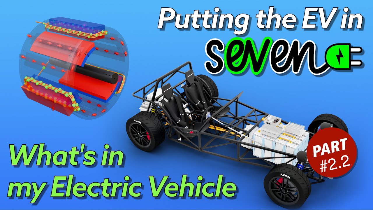
This is the second of two explainer videos I’ve created to help YouTube viewers understand the concepts, terminology and physics of what’s going on in my Caterham Seven EV conversion.
I’ve made these two videos so I can refer back to them in my progress videos and so I don’t need to explain each concept again and again.
The first video (here) covered the basics of the two different forms of electricity used in an EV, Alternating Current and Direct Current.
In this second of the two explainer videos I cover all the components I’ll be using in my minimialist EV conversion.
I had initially scripted these explainers as a single, long video. But it soon became apparent that it was going to be too long, and separating the material into “electric” and “components” seemed to make for a good delineation. I did do a few scripts with three separate parts, but in the end that was going to be way too much for anyone to stomach!
TLDR;
Ok, so the “Too Long Don’t Read” of this video is that this video is a whopper!
This video and it’s sibling (here) have taken me 8 months to produce. The 9 minutes of the first video and the 19 minutes of this second have taken FOREVER to get done, and don’t really reflect the time that’s gone into them. I’ve created countless 3D models, animations and scripts, and then editing it all together has taken an age too.
If you want me to put a number on it, then I wouldn’t be surprised if the two videos took well over 500 hours to create.
Most of the 2D animations (block diagram, battery cell animations, battery animation, AC and DC simple circuits) were done in Apple Motion (the final video is done in Final Cut Pro).
The 3D animations are all created in Blender (motor internals, car, car and charger, car being charged, fast charger scene, torch and house being lit etc ).
The biggest of those tasks has been the Motor Internals animation in Blender, see below.
Motor Internals
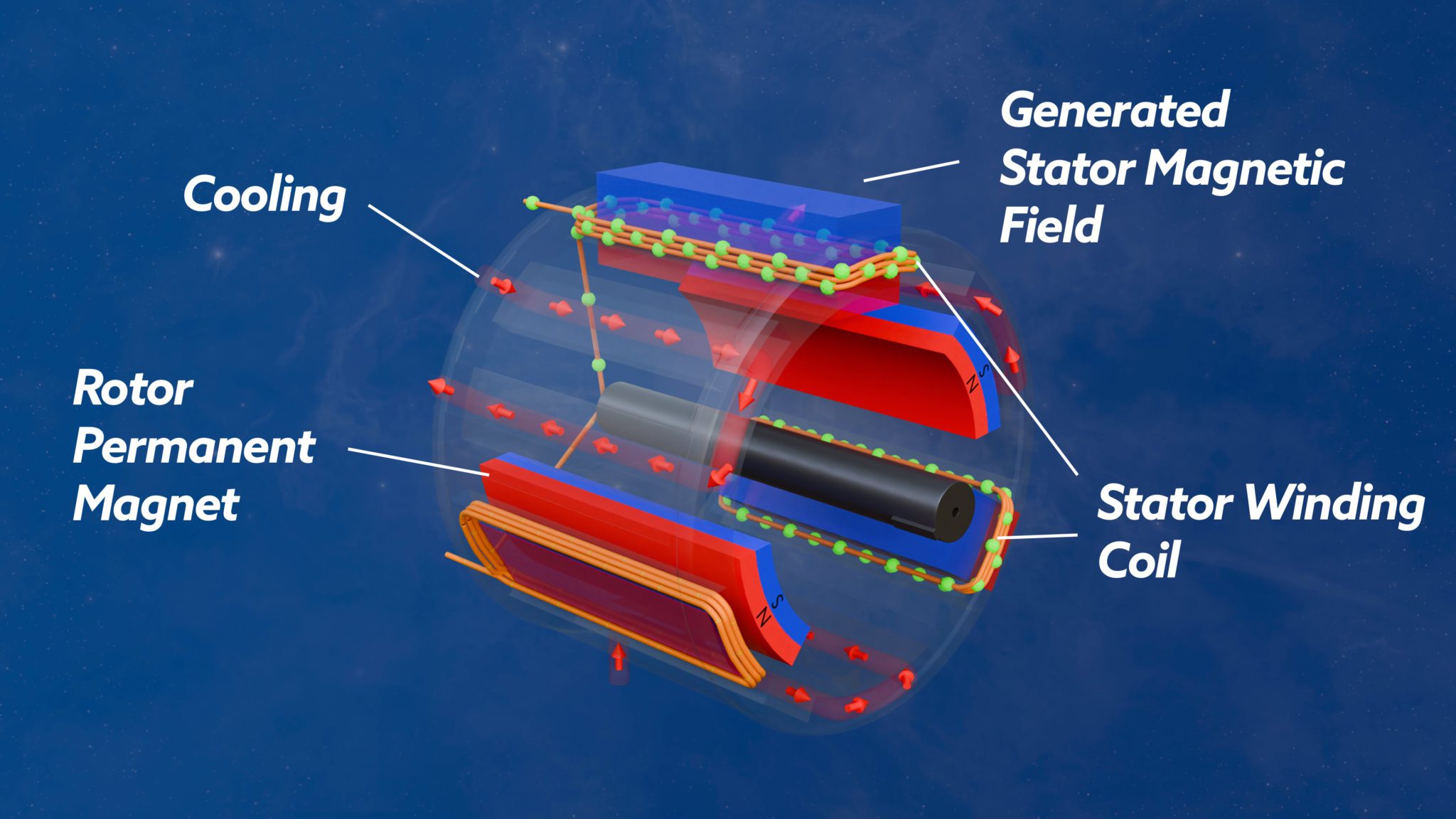
The Motor Internals animations are a simplification – because a real Permanent Magnet Synchronous Motor (PMSM) would have both more stator windings and more permanent magnet poles. I may make a future video that better replicates both aspects, but that would be more to create a WOW! Factor rather than being particularly useful as an explainer. It would be fun to do though!
It never ceases to amaze me what Blender can do, and for that matter what I can do in Blender.
This set of “Motor Intnerals” videos took me about a week to create initially (probably with 8-10 hour days). But was then iterated on for a few more weeks as I refined what I wanted the animations to show.
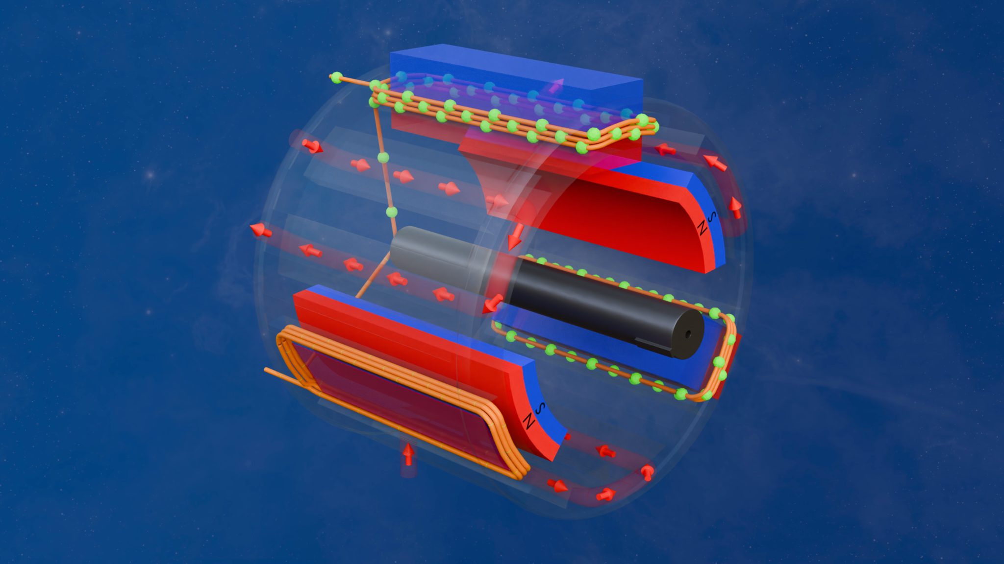
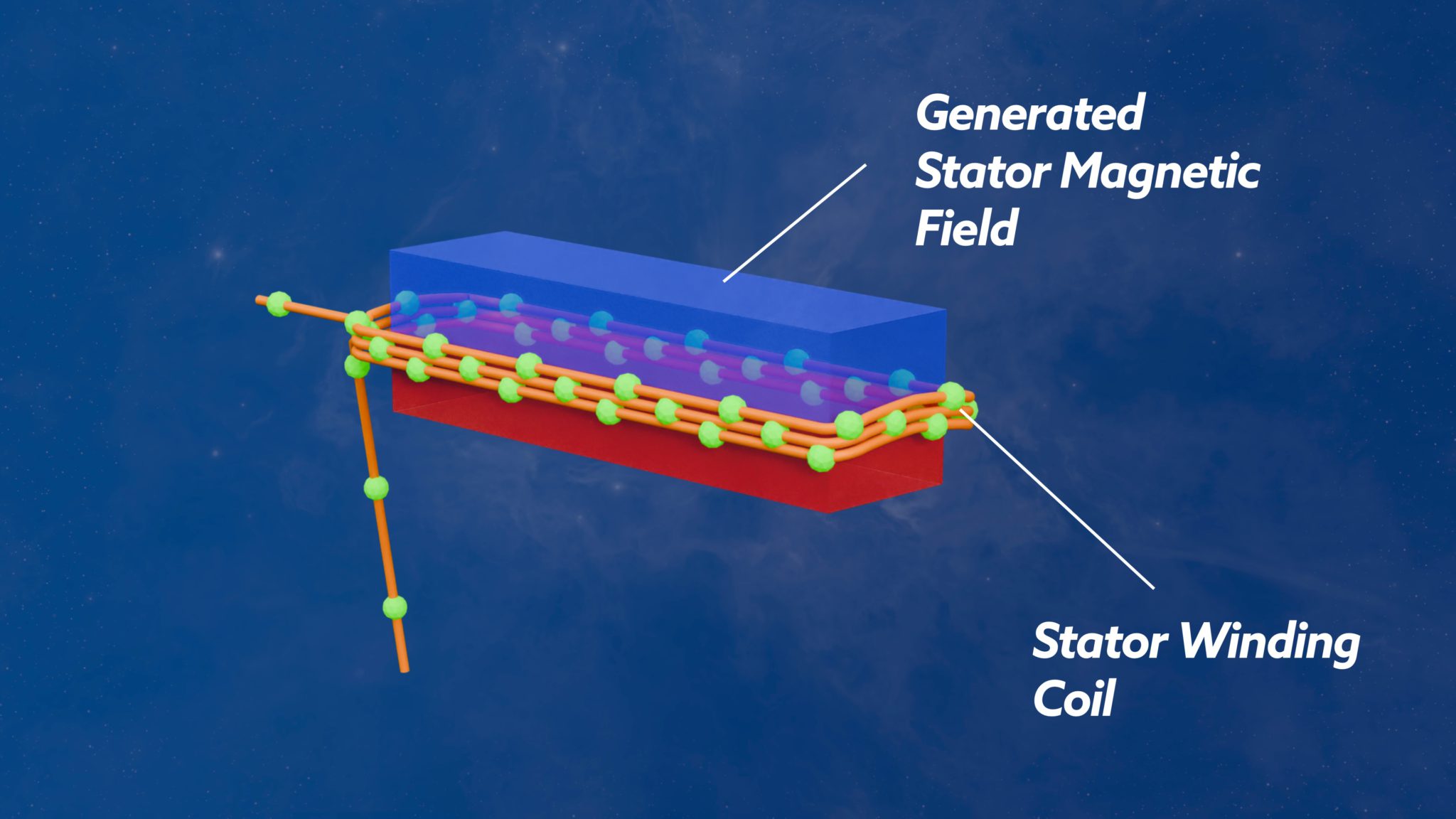
What I’m really proud of is the “real” physics of the animations. The crux of this is that the currents in the stator windings (green blobs: size, direction and speed) along with stator magnetic fields (the semi-transparent stator fields) are all “reasonably” accurate. The animations use Blender Geometry Nodes to calculate the conceptualisations accurately.
The size of the green blobs and their speed, reflect the sinusoidal nature of the currents in the stator. Likewise, the magnitude of the generated transparent magnetic stator fields are also representative of the flowing currents (see below) – again the field size is also sinusoidally driven.
In a similar vein, the green “force bars” depict the forces that would be created between the stator fields and the permanent magnet fields (again, see below).
I really struggled to come up with a concept for the forces being created by the magnetic field interactions.
At one point I’m ashamed (as an electrical engineering graduate) to say that I completely got the workings of a PMSM wrong. There’s whole ‘nother layer of complexity to PMSM’s where Clark and Park transforms are used to determine D and Q vector spaces. I’d completely got the way they work wrong and so I created a set of animations where throttle pedal position was used to modulate torque by changing the angular separation of the stator and rotor magnetic fields, i.e. adjusting current in the D direction.
I now appreciate that this angle is what determines the “field weakening” aspects of a PMSM (something I totally don’t go into in this video) and which meant I had to recreate the animations for and re-edit that section of the video. HOWEVER, this was a huge educational point for me. I did a ton of power and motor electronics in my under-graduate electrical/electronics engineering course but I graduated in 1989, and PMSMs didn’t really exist then. The powerful neodymium magnets used in PSMSs weren’t commercially viable then, so we didn’t cover how these motors work in my course.
Fortunately, YouTube came to the rescue and just by chance looking for something else, YouTube served me up a video on how motors work from Jentzen Lee and I did the “matrix spike in the base of the brain” thing and I had a “I know kung-fu” moment.
Here’s Jantzen’s first video in his playlist. I suspect this video is only useful if you’re an electrical graduate, it’s easy to follow, but perhaps only if you’ve got a good grasp of the maths and physics going on. It’s also not specifically about PMSMs… and he talks about these being DC motors where we would more normally think of them as AC… but the series is really good if you want to get deep and dirty in the physics…
To be honest, I’m still not totally sure how practical implementations of PMSM’s drive their Q and D parameters. It seems many motors might assume that the max speed of the motor can only be achieved with field weakening. This is something I’m going to have to get my head around when picking a motor and inverter pairing.
Motor Internals – BlendEr
Ok… so the Motor Internals animations were created in Blender… over, initially, a few days, but in total over a few weeks.
The process is a bit of a “standing on the shoulders of giants” thing, or at least my shoulders. The animation is really five parts.
- Modelling
- Stator Current Animations
- Stator Magnetic Field Animations
- Stator Cooling Animations
- Python
Let’s go into way too much detail about each of those…
Motor Internals Modelling
This was actually fairly straight forward. I modelled the stator, stator windings, rotor, rotor output shaft and a stator magnetic field all in the regular modelling space – see models in image below.
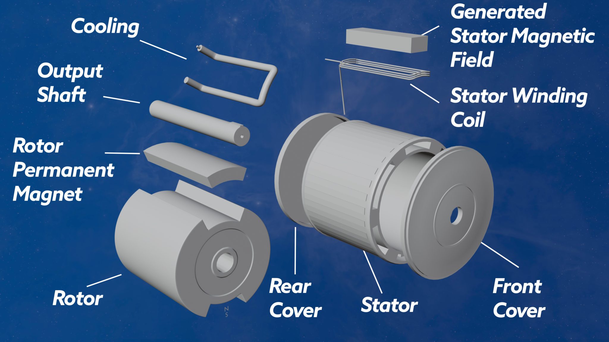
The one, perhaps, unusual thing, is that I modelled the stator windings as a curve and not a mesh. Using a curve probably does make a lot of sense, but it was mainly because I could use something I’d developed previously (standing on the shoulders of giants) to animate the coolant flow in a Duratec engine (still not released – grrrr!!!!).
I won’t go into the details of the Geometry Nodes setup, but the fundamentals of it is that I modelled a curve in the viewport, then took that curve into Geometry nodes to give it thickness and animate the blobs onto it. I go into more detail in this post.
These models were created quite quickly in a few days. What took longer was the “conceptualisation” of what I wanted to say, and therefore the back and forth between Final Cut Pro and Blender to hone a set of animations that told the story the way I wanted. At least I am now proficient enough to be able to execute these animations in Blender the way I visualise them in my head. Then its just a case of getting the visual right in the void between my ears!
Stator Current Animations
The green blobs and mesh renderings of the stotor windings is done using Geometry Nodes. This was a rip-off from the Duratec cooling animation work that I’ve been working on for years. However, the blobs moving along wires was like the arrows moving in the pipes of the cooling animation, and so I could snarf most of the Geometry Nodes setup and re-use it.
The difference here though is that the blob size and speed needed to be proportional to the current flowing in the coils.
And this is where I cheated a bit.
In a real motor the stator currents will drive the rotation of the rotor. I probably could have modelled it this way, but it was actually easier to animate things the other way around… I animated the rotor, in Python (see below), and then derived the stator currents, and for that matter the magnetic fields we talk about next, from the rotor’s rotation.
So, the Geometry Nodes setup for the stator windings takes inputs of a rotational object (the rotor), an angular offset (so the same Gemetry Nodes setup can be used for all three stator windings) and various other parameters such as winding diameter and the textures used to render the windings and the current blobs.
Stator Magnetic Field Animations
This one was also a Geometry Nodes setup. But much simpler than the stator winding GN.
In this instance I just took a rotation object (the rotor) and used its angle to determine a Z-scale that I applied to the Rotor Magnet meshes.
That way the stator magnets grow and shrink as the rotor rotates.
Stator Cooling Animations
This is another Geometry Nodes setup, and a direct copy of the Duratec Cooling Animation arrows.
I did decide to do this animation after I’d already built and animated the rest of the model. So I had to add “cooling channels” and “cooling beziers” that ran inside the channels.
There’s then three of each cooling channels and cooling beziers. There’s no correlation between rotor angle and these animations.
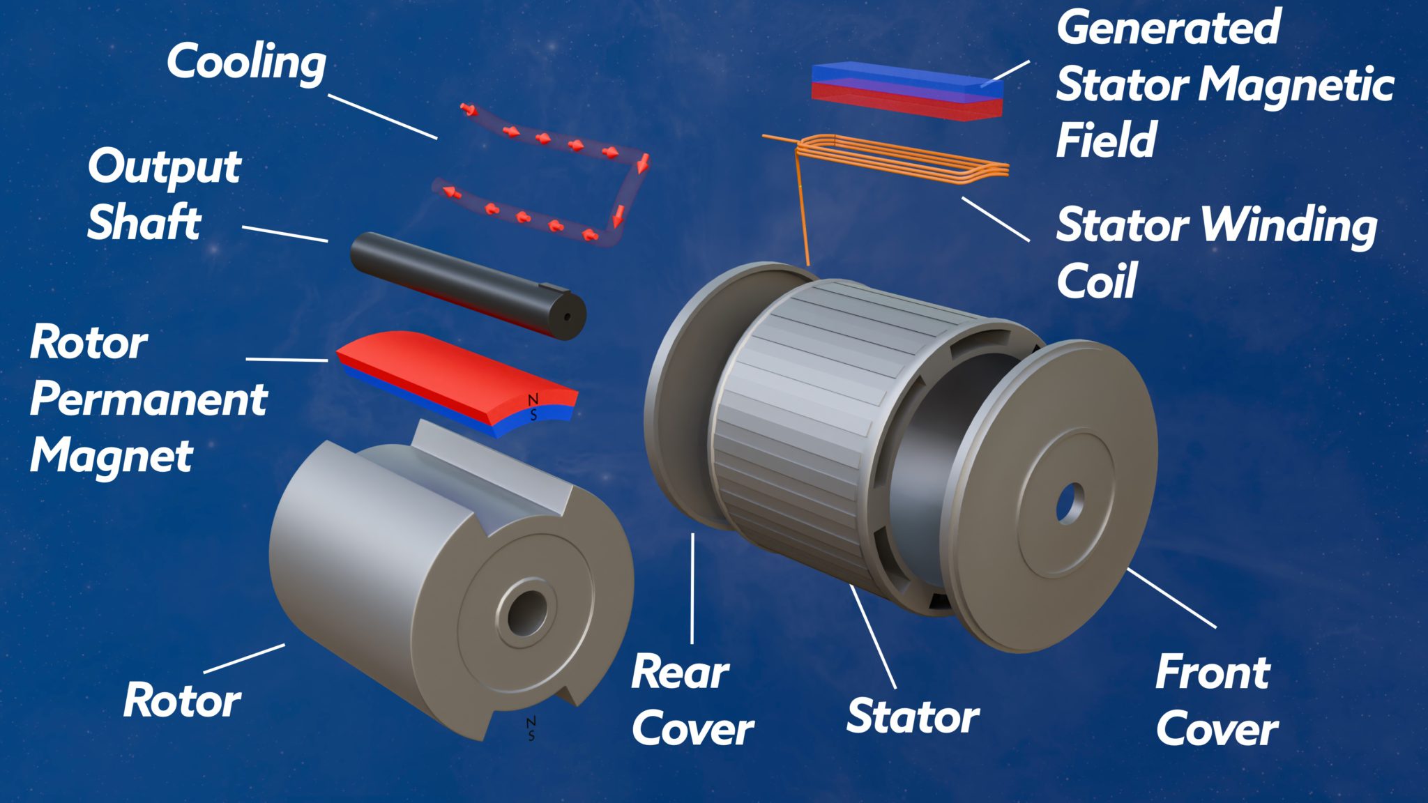
Force Vectors between Magnetic Fields
This one probably didn’t come off as well as I’d hoped. You can see in the image below that I overlaid green bars between the stator generated magnetic field and the rotor’s permanent magnets.
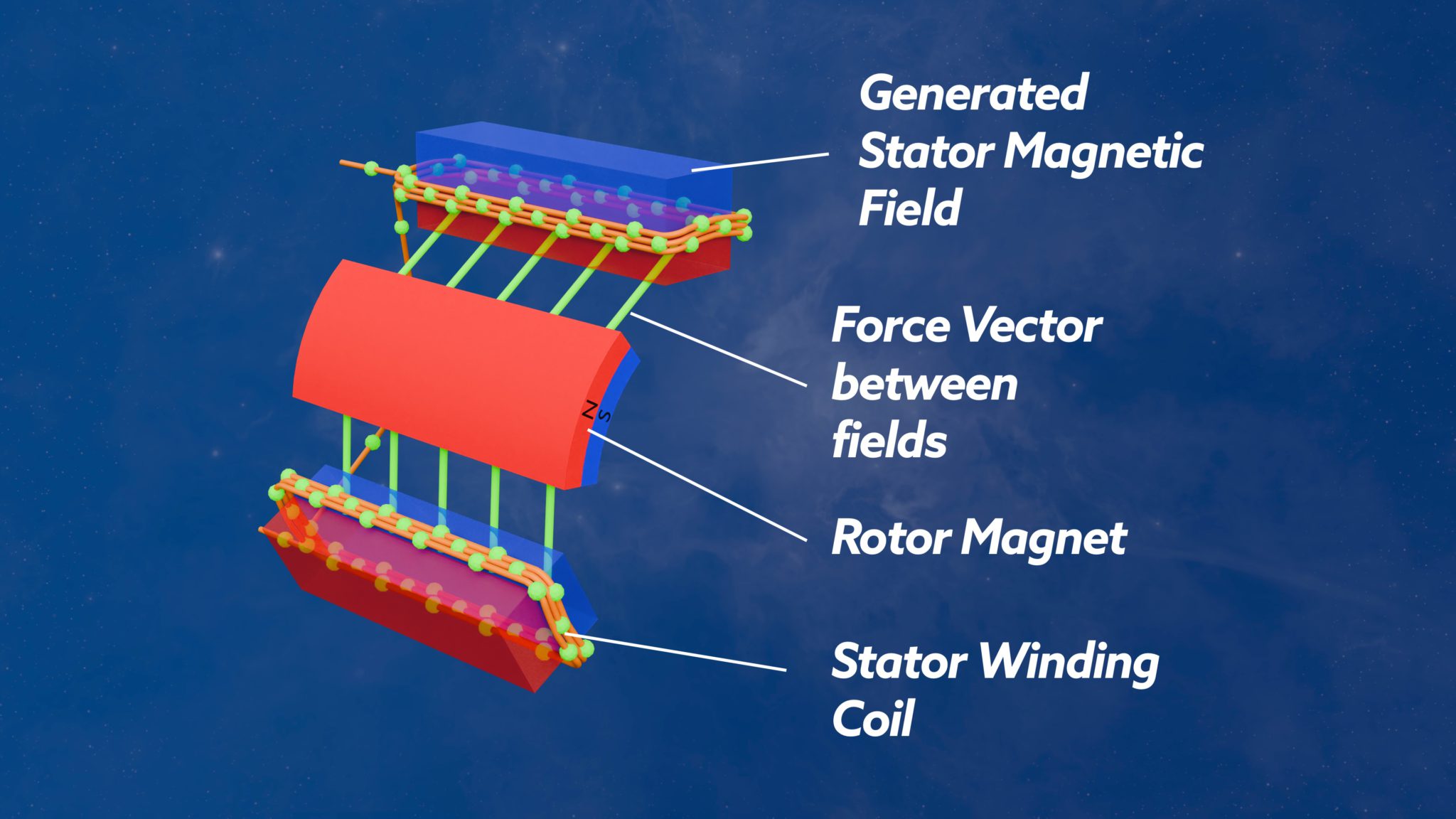
The green bars don’t really jump out as being the forces between the magnetic fields. I really wanted arrows showing the direction of the field, and probably for them to be colours to show which was pulling and which was pushing.
I tried arrows, but it was proving too tricky to get the arrows positioned and scaled so they showed well through a full rotation of the rotor. I also ran out of time trying to figure out which vectors were push and which were pull.
Perhaps this is something I’ll come back to and put out a short with the updated vector rendering.
Motor Internals Python
Now we’ve got all the models and they’re animated, we need a bit of cinematography…. I.e. I (mainly) used Python to animate a camera rig when I wanted orbits of the animations.
The one caveat to this is that I “animated” the rotor spinning in Python. That way I could synchronise the rotor doing complete rotations before/during a camera orbit – I didn’t want a camera orbit to start before I had one complete non-orbiting rotor rotation.
I use Python to do these cinematic orbits etc, so I can change the duration of the orbits, how close the camera is to the subject and other stuff like frame rate, without having to re-keyframe the whole animation. By using Python to create the key frames, I can tweak lots of parameters and automagically recreate the key frames at a single keystroke – that would take forever if the key frames were generated manually!
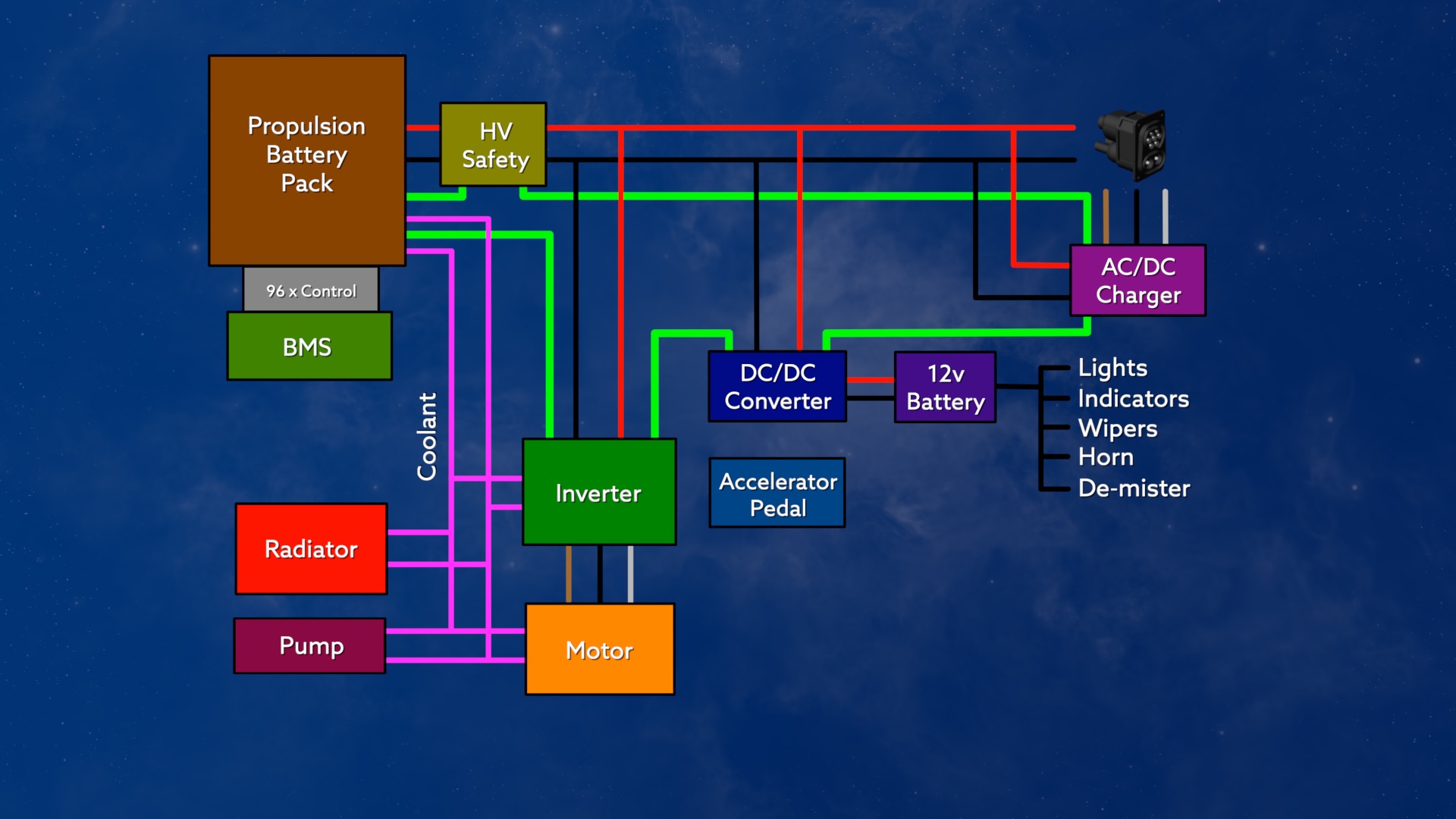
Simplified EV Block Diagram
Which brings us on to an Apple Motion Block Diagram generator.
Like most of these animations, this Apple Motion project started off in much simpler form. Over the months it took to get these videos done, the generator evolved to allow animations of all the various current flows but also to reverse their direction when going from motoring to generating.
Below is an image of the block diagram showing the motoring mode. And below that is the parameters published from Motion to Final Cut Pro to control the animation.
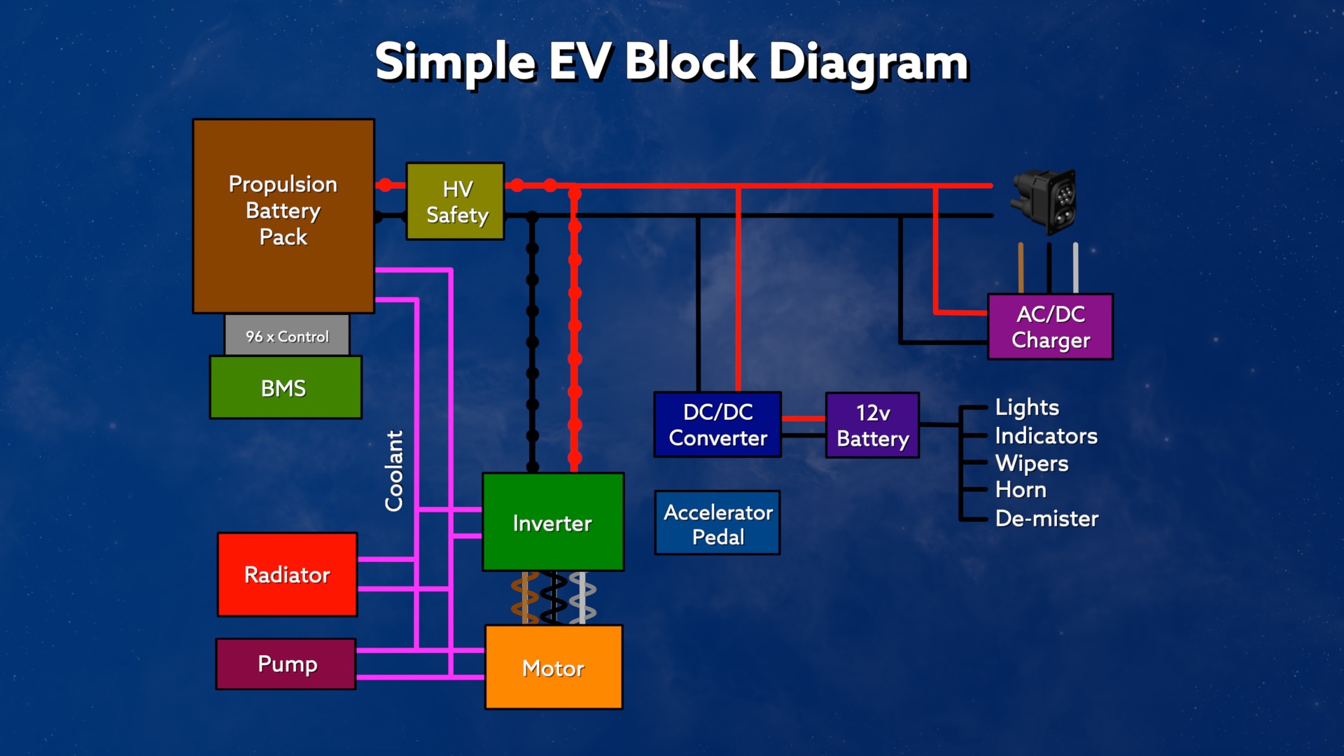
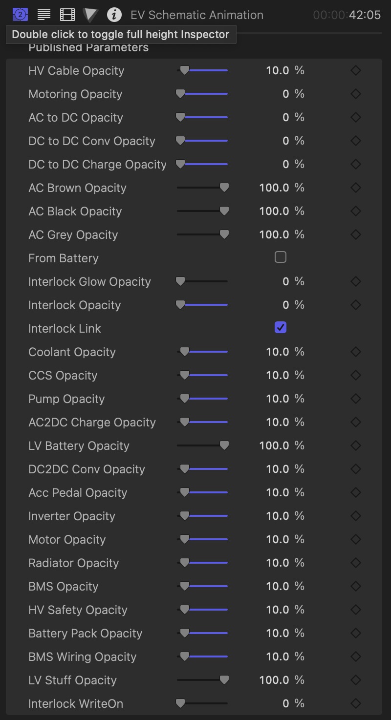
This generator has many features controlled through the various object’s opacity, including three phase AC animations on the connections that carry AC.
One of the last features to be added to the generator was the addition of some interlock animations. The interlock circuit can animate itself into the diagram, show a break in the line, and can have a glow halo added. All these features were used in the video to emphasise how the interlock worked and what happened when any of the connections were broken.
Charging Animations – Blender
There were also a few charging animations created in Blender.
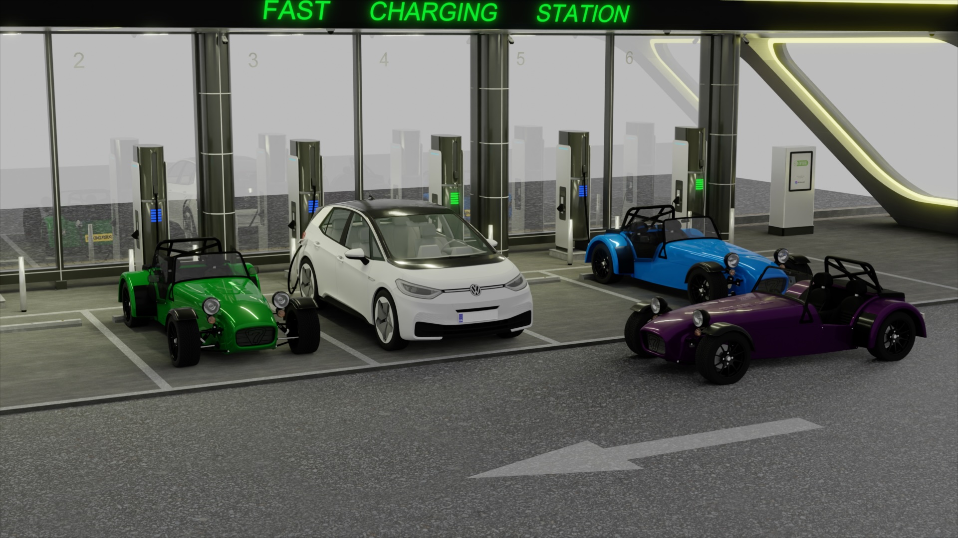
The first is “drive by” animation of a few Sevens and an ID3 being charged at a fast charging hub. The green and blue Sevens are a nod to two projects I know that are working on EV Sevens. The purple car in the foreground is obviously a nod to my Purplemeanie and the ID3 is there a) because I have an ID3 and b) because I have an ID3 I also bought a 3D model of the ID3 to use in exactly these sorts of situations 😉
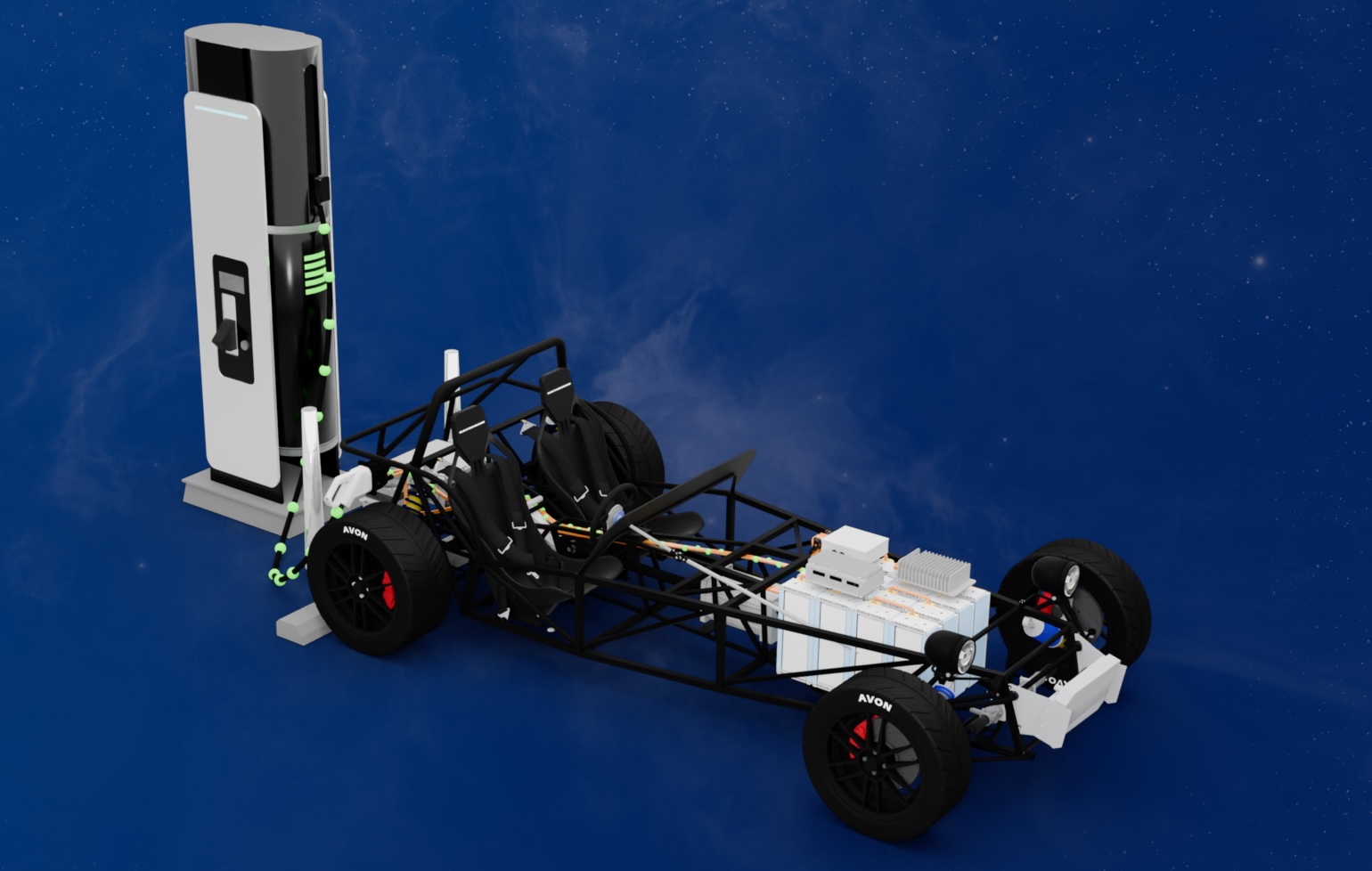
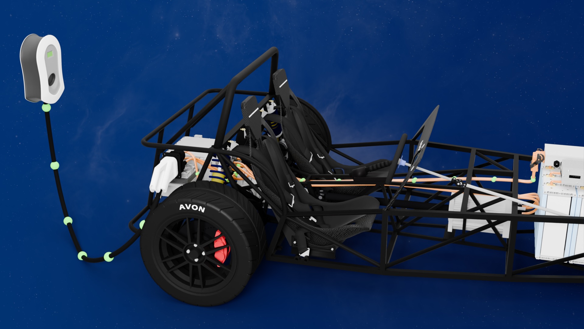
Next we have a pair of animations showing current (green blobs) charging a Seven EV chassis, one animation each for fast and slow charging. The fast charging animation uses a fast charger model downloaded from the internet. The second slow charging animation is of a MyEnergi Zappi home charger that I have installed at my house.
Both these animations use the same Blender Geometry Nodes setup that I’ve used a number of times to animate current on a curve (the Motor Internals animations above) and the coolant flow in an ICE engine that I’ve also talked about (but still haven’t published).
Video Chapters
- [00:00] Introduction
- [00:20] Project Overview
- [01:52] The Components
- [02:38] 1. Motor
- [06:46] 2. Transmission
- [07:31] 3. Inverter
- [09:44] 4. Batteries
- [11:08] 5. Battery Management System
- [12:16] 6. Charging
- [12:48] 6.1 AC Charging
- [13:12] 6.2 DC Charging
- [14:09] 6.3 DC-DC Charging
- [15:14] 6.4 Common Charging Socket
- [15:39] 7. Cooling
- [16:10] 8. Safety and Wiring
- [18:04] 8.1 Interlocks
- [18:36] Wrap-up
Transcript
Introduction
[00:00] What’s the bare minimum stuff you need for an electric? Cal conversion. In this 2nd part. of my EV technology miniseries. I’m going to take a look. Of what components you’ll need in a minimalist electric car conversion?
Project Overview
[00:23] This video is part of my Putting the EV in Seven project. Where we’re taking. An unloved. 10 year old, Caterham… 7 drift car. And converting it? beat an electric vehicle. We’re removing the internal combustion engine and putting in an electric motor, batteries, and control electronics to create an EV interpretation. of the classic 1957 Pocket Rocket. At the end of which, we hope to be able to say whether converting such an iconic car really is an appealing option for feature conversions. As the project progresses.
[00:54] There’ll be a mixture of these explainer videos. Along with the usual progress videos. But it’s these 1st videos that I’ll keep asking you to come back to if you want to know what’s in this EV project and what some widget or other does. These explainer videos are going to be relatively technical. So I’ll try and keep the content to about high school level physics. If you’re a more advanced viewer. Please just accept. But I’ve applied a layer of gloss to the basics.
[01:18] And then let me know in the comments below, if you’d like to see any more of these videos, more in-depth theory. The 1st explain a video. Was all about the differences between AC and DC. Used in an EV. While in this 2nd video, Well, now take a look. That the components will need to use in the conversion. And how they interact with each other. At that point, We should have all the basic principles of a no-frills EV nailed down. And we can then get back to the actual progress of my project car.
[01:44] And if this is your 1st time watching this series, Than my intro videos. We’ll give you some. I do this. Along with the background to the project.
The Components
[01:55] Ultra cutdown EV conversion, we’re going to need a few core components on our block diagram. Firstly, a motor to make us move. Transmission to get the correct wheel speed and drive to the wheels. An inverter to drive the motor, battery pack to store all our propulsion energy, battery management system to control the battery pack, charging circuitry to get new energy into the vehicle, cooling to stop it all overheating, and safety circuitry to keep the vehicle. And are safe. We’ll cover each of these in the following sections.
[02:28] But you can also skip ahead using the chapter markers. So let’s get into it and take a look at the minimum components needed for an EV conversion.
1. Motor
[02:40] The motor is probably the 1st component that needs to be decided upon in a conversion. But whilst it might be the 1st decision to drop out of the design. In reality? The process of deciding on the component. Is a back and forth between performance? Availability. Cost and space planning. It will depend heavily on your project goals as to what the relative priorities are. But for me, the motor was the critical decision setting many of the other parameters. The motor is what turns the energy stored in the battery pack into forces that drive the wheels.
[03:09] As we saw in the 1st video of this series. The motor takes 3 phase electrical energy from the battery. Through an inverter and turns it into rotational energy. The mainly adopted motor type for EVs. Is permanent magnet synchronous motors, or PMSMs. A permanent magnet. Synchronous motor. Has 2 main parts. A status? And a rotor. The data forms the outer casing of the motor. And the rotor fills a cylindrical cavity inside it. By passing an alternating current through coils in the data.
[03:41] We create a magnetic field, which has both north and south poles. attract and repel the magnetic poles of the rotor magnet. Which pushes and pulls the rotor around. The frequency of the sine waves is what governs the speed that the rotor will turn at. And we’ll come to this again when we talk about the inverter later. Electric motors also perform. quite differently to ICE. Internal combustion engines. They create a large Talk from standstill, and happily operate the many 1000s of revolutions per minute.
[04:12] They’re a perfect option for producing power. From standstill all the way up to whatever maximum speed we need for our vehicle. This also means. We don’t need a traditional multiratio gearbox to offset the narrow… High revving. Power and torque curves. Of an internal combustion engine. We’re saving weight on a complicated gearbox. And a bunch of other associated stuff. It’s also worth pointing out that an electric motor is not 100% efficient. For instance. The resistance in the coiled data wiring creates heat.
[04:41] If the motor is generating a lot of power. Then this heat created in the data. May require the motor to be called. So we’ve seen how the speed of the motor is governed by the frequency of the sine wave currents we apply to this data. The final part of this motor puzzle is how we translate accelerator pedal position to motor speed and talk. Okay, now hold onto your hats. We’re going to get a bit technical. So we can see how the accelerator pedal.
[05:07] Increased talk. I’m going to artificially stall the rotor. But keep the state occurrence flowing. This shouldn’t ever happen in practice. But it’ll be helpful for us to see what’s going on. We say that pedal position equates to a parameter. That we call demand. And then we set demand to be proportional to the talk requested from the motor. When we press the accelerator pedal, inverter increases the current in the state of windings. Which, in turn, increases the magnetic field produced by the data.
[05:33] This then creates a larger force between the state and magnetic field and the rotor permanent magnets. And finally, We know that talk is just forced times distance. This increased talk can do a couple of things for us. Firstly, the extra torque can increase the speed of the motor and therefore the vehicle. Secondly, it also translates into the motor working harder at the current speed. And that’s what you need, if, for instance, you’re going up a hill. There are many other nuances about how the data and a rotor interact.
[06:04] with each other, like back EMF and field weakening. But we’ll leave them to a future video. So let’s recap on where we’ve got to with motors. Permanent magnet, synchronous motors. Have a stater with coils that create a magnetic field. Which interacts. With the permanent magnets installed in the rotor. The 3 phase AC currents in the stater coils. Change 1000s of times a second. To push and pull the rotor with a force that makes the vehicle move. The frequency of the data sine waves controls the speed of the motor.
[06:34] And we also saw… That the amount of current we applied to this. data windings. Determines the talk produced by the motor. Which brings us to the next component in our EV, the so-called e-transmission.
2. Transmission
[06:48] Our motors run at high RPM and only have one output shaft. To overcome those 2 issues. We need some sort of gear reduction system on the output of the motor. And a differential. Split the drive from one shaft. To 2 that will run the wheels on both sides of the car. If we manage things well, then the differential and the motor output reduction, Can be handled? By a single transmission component. gets called an e-transmission. In my conversion. I need a will speed of around 1900 RPM.
[07:18] To get to a vehicle spin. The track use. Which is about 125 miles an hour. Clearly way faster than you can use on regular roads. But not unreasonable for track use. Now let’s look at the electronics we need to drive the motor.
3. Inverter
[07:33] The job of an EV Inverter. Is mainly to convert direct current to 3 phase alternating current. energy from the battery and feeding it to the motor. It is also used to do the reverse when the motor is generating. Converting 3 phase AC back to DC and putting it back into the battery pack. Now, to create the 3 AC sineway. An inverter will use a chopping design. Where it switches the battery’s DC voltage on and off to create what is known as a chopped output.
[08:01] The timing of this chopping action is performed precisely. So as to create an approximate sine wave. This is then smooth to produce the final sine wave, which can be applied to the motor. Three sine waves are created by the inverter. Each offset by 13rd of a cycle. In the motor we’ll be using, those AC sinewaves will be cycling at about 500 hertz. But the switching, chopping frequency of the inverter will perhaps be up at around 40 times that frequency or around 20 kilohertz.
[08:30] We also saw how it creates the sine waves at the right frequency and current needed to control the motor. To control this. rapidly spinning rotor, and quickly changing sine waves. The inverter needs to know more of what’s actually going on with the position of the motor’s rotor. To do this, the most common solution is to use what is known as a resolver, incorporated into the motor. The output of the resolver is then fed into the inverter, and added to all the maths being performed there.
[08:58] We won’t get into the detail of this mass, known as digital signal processing or DSP. But it’s worth mentioning that the inverter DSP is continuously checking the rotor’s position. State occurrence. Demand. and talk and comparing them against what it thinks they should be. It then adjusts the state occurrence, compensate for any changes. Many 1000s of times a second. Another side note here. Is that while the transistors used to chop. The DC into AC are very efficient. They’re not 100% efficient. They have a small amount of resistance when they’re on.
[09:29] Conducting current. And because the currents are so large in an EV, that means the transistors dissipate a lot of power. And power means heat. So this is another area where cooling is usually required to keep the transistors from getting too hot.
4. Batteries
[09:46] A battery pack is what stores all the energy to make our vehicle move. It’s stored in the battery as electrochemical energy. And in the case of the lithium iron batteries that we’ll be using, Charging or discharging the battery physically moves lithium ions between the +and negative sides of the battery. When we want to go somewhere in our vehicle, we convert the chemical engine. Back into electrical energy, which we then apply to the motor to make us go forwards and backwards. We can also charge the battery.
[10:14] By using regenerative braking and turning a bit of our speed. A kinetic energy. Back into electrical and then chemical energy again. A battery is made up of many hundreds or thousands of smaller batteries called cells. Belgian series increase the voltage. Cells in parallel increase the current. And we need the correct. Voltage. drive the motor efficiently. While having enough current to deliver the total power we want. The total energy the battery can start. its capacity. Measured in kilowatt hours. Determines our range.
[10:43] And how full the battery is, is what we call its state of charge. And while batteries are pretty good at storing. and delivering electrical energy. They also, like everything else we’re talking about, are not 100% efficient. They create heat as they operate. And with the high power throughput of an EV battery pack. And a pumped calling system. will also be required to keep battery temperatures in check.
5. Battery Management System
[11:10] An EV has another controller brain. Known as the battery management system or BMS. Lithium cells. And not as forgiving as lead acid. is used. In the low voltage systems. Of internal combustion engine vehicles. To keep them healthy, lithium cells need to be charged and discharged carefully. And to do so, the BMS monitors the voltage. Current and temperature of the vehicle’s battery bags. When the motor is running, the BMS will communicate with the inverter. Informing it. Thanks the battery pack. Is too hot.
[11:42] And telling the inverter. That it needs to back off on the power it’s telling the motor to deliver. It’s done to keep the batteries as healthy as possible and to increase their longevity. The BMS also has another trick up its sleeve when managing battery health. It can also call for the batteries to be called by a caller circuit. Managing the temperature of the batteries. Is not just about trying to keep them cool. As well as a cooling radiator. The battery callant circuit.
[12:06] May also have a heating element incorporated. To bring the battery pack’s temperature up. To improve both health and charging times.
6. Charging
[12:18] I’m going to break the charging down into 4 sections. Regenerative charging? Onboard low power AC charging. High powered DC charging. And on board low voltage charging. We’ll also talk about the charging socket while we’re at it. Regenerative braking. is one we’ve already talked about. But that doesn’t bring new energy into the car. So we’ll concentrate here on new power being added. With low power AC. high powered DC charging.
6.1 AC Charging
[12:50] Onboard charging is often included via a low power but slow AC to DC charger. It takes AC grid power into the car and converts it to DC to be fed into the vehicle’s propulsion battery pack. This method is best used for overnight street side or home charging. We may or may not include one of these in our project.
6.2 DC Charging
[13:14] The 2nd new energy charging method. Is to use a roadside DC-DC charger. That takes power from a charging station. And directly charges the high voltage propulsion battery. With this method. There’s a large roadside box that converts grid alternating current into direct current for the car. These fast and super fast DC charges feed the vehicle with exactly the voltage the propulsion battery pack needs. Meaning the vehicle doesn’t do any voltage conversion when taking high voltage DC to charge the car.
[13:45] The vehicle’s BMS and charging controller make sure the charger provides both the correct voltage and current for the car. Both need to be monitored to make sure the power being delivered doesn’t compromise battery health or longevity. From our perspective, DC fast charging will be important. We will need to charge on long journeys or on track days. And we don’t want to be sat waiting. For a slow onboard charge to finish.
6.3 DC-DC Charging
[14:09] While we’re talking about charging, We need to discuss a side issue. EVs also have a low voltage DC-DC converter in the vehicle. It takes power from the propulsion battery pack and charges a low voltage battery. This battery is then used to power the ancillaries, such as lights, wipers, horns, and pumps. You might think that with a large, high voltage propulsion battery sitting in the car, And all the high voltage power electronics floating about. You wouldn’t need a low voltage battery in an EV.
[14:37] Well, that turns out not to be the case, for the following reasons. Firstly, It’s much simpler to reuse all the low voltage ancillaries. Especially in a conversion like ours. Secondly. If the high voltage battery fails, Or runs flat. Then you need a backup battery to run your safety function, such as hazard warning lights and your main lights. Finally, if you do manage to flatten your high voltage propulsion battery pack, Then it would be a good idea if the car had another source of energy to power all the electronics needed to reliably kickstart the charging session again.
[15:07] It therefore makes sense. To have a separate. Low voltage battery in the car. And this is where a DC-DC converter comes in.
6.4 Common Charging Socket
[15:14] And to finish off the discussion about charging. Let’s talk about the charging socket. And I’m talking here about the CCS or common charging socket. That’s used across Europe now. The charging socket allows for both low power AC and high powered DC charging. It also provides a locking mechanism to stop you. Or somebody else. From removing the charging plug in the middle of a charge. So that’s all the charging and voltage conversion colored. Let’s have a look at calling.
7. Cooling
[15:41] Highly efficient electrical drive systems. We’re supposed to do away with the mucky stuff of oil. In eyes. But while many people doing EV conversions would rather ignore it. The reality is that high powered drivetrains still generate a lot of waste heat. It would be nice to think that they could be air cooled. But unfortunately. Even with the efficiencies in the 95 +% range. Generating. 10 of kilowatts of waste heat. A full throttle.
8. Safety and Wiring
[16:11] Let’s finally talk about a casual category that I’ve lumped together and called HV safety and worry. This is a category of. That is all pervasive throughout the vehicle. It distributes both DC and AC power at 100s of volts and 100s of amps. While also being sent at quite high frequencies. There’s a lot of power being distributed around an EV. And if you choose the wrong size wiring, then it’s quite possible to lose a lot of that power, just in resistance of those wires alone.
[16:38] But on the flip side, If you pick overly conservative wiring, meaning the wiring cross section is too big, then you’ll be carrying many extra kilograms of copper around for very little benefit. Most DV conversions have one or more boxes. That house a few critical but otherwise disparate components. Included in this, we have things like precharge circuits. To protect the inverter and motor when applying high voltage to the motor on startup. Contactors. They’re a fail safe. For a few areas of the car.
[17:07] Interlock wiring that I’ll talk about in a bit. And battery junction boxes. Contactors are essentially just high voltage relays, a switch that either allows the flow of current or not, and can be used for both DC and… AC systems. An EV will typically have contactors spread throughout its high voltage circuits, protecting both you and other parts of the car if faults or accidents occur. If you’ve ever started or stopped an EV. Or plugged one into charge. You’ll have heard a loud click or series of clicks.
[17:39] This sound. Is the contactors opening or closing? Before you can move off in an EV, the car has to perform diagnostic tests, and we’ll only contact us. If all of those tests pass. If any fault occurs while driving, or the vehicle is in an accident, then the vehicle’s control systems will the contact is to disconnect all the HV components from each other. Which leads us to a very important concept in EV cars.
8.1 Interlocks
[18:03] Interlocks. An interlock? Is often implemented as a long physical wire. That connects through each of the EV’s components. Stringing from one device to the next in series. If the interlock wire is broken, by fault, accident. Was someone opening something at the wrong time? Vehicle will open all the contactors. I make it as safe as possible. This protection is a very physical system, with little or no electronics or software governing its action. That way, it will provide its protection in the most fault tolerant resilient way possible.
Wrap-up
[18:38] And that’s it for this rather long episode. We covered a lot of ground in this video, looking at all the major components of our EV conversion. We looked at how motors work and how they take electrical energy and convert it to rotational power. I then looked at the e-transmission, we’ll need to take the motor output and drive our wheels. After that, we looked at the inverter and how it creates the sine waves at the right frequency. Need to power a motor.
[19:02] And then after the inverter, we looked at battery packs, how they are configured, and how they work. Finally, we looked at charging, cooling, and safety. Hopefully that will be enough EV technical background to get you through the coming progress videos, as well as being a video you’ll be able to return to as we progress through the project. If you’d like a more in-depth version of anything I’ve covered here, then let me know in the comment section below, and I’ll do my best to put a video together.
[19:27] Stay tuned, like and subscribe to see updates as they come out, and I’ll see you next time when I’ll definitely have started to do some converting.

Leave a Comment