
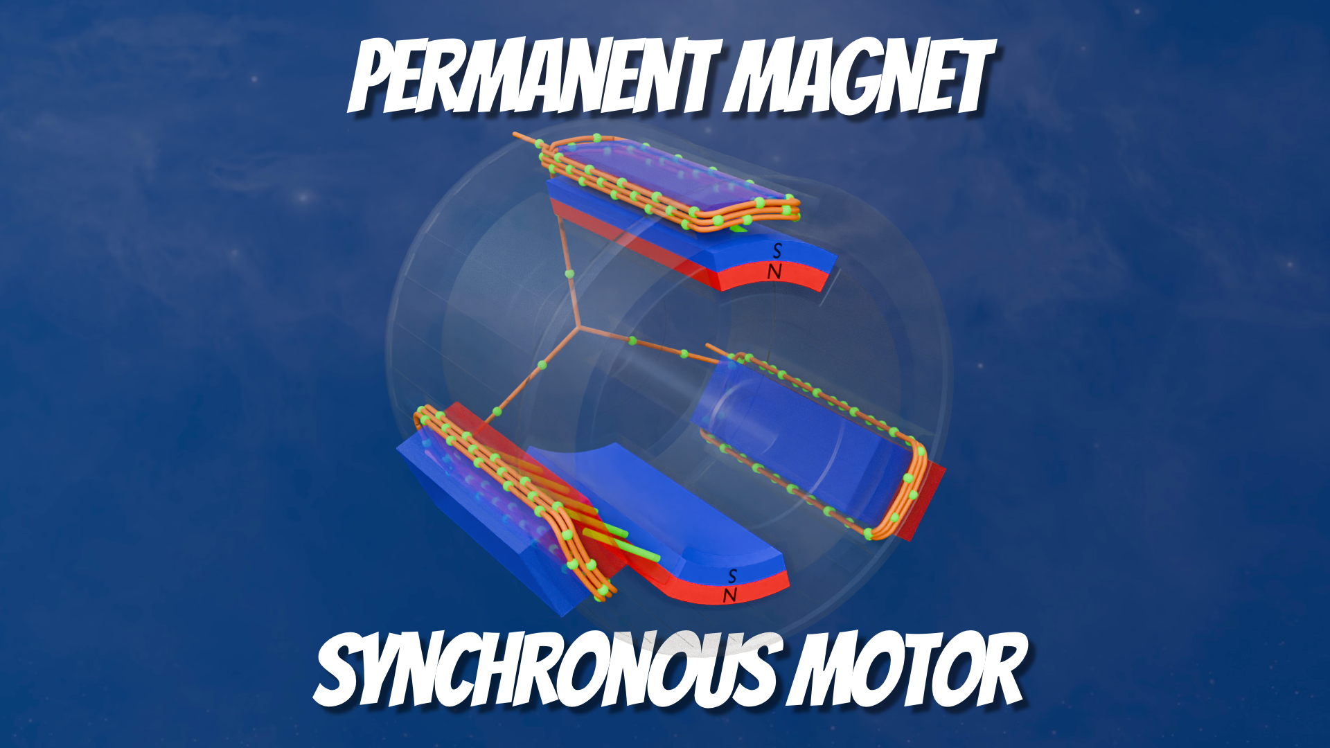
As part of a larger explainer video I wanted to show how a Permanent Magnet Synchronous Motor Works.
I wanted to show how the stator and rotor interacted with their respective magnetic fields and currents.
The video shows how a simplified motor is constructed with a Stator and Rotor and then breaks those down to show their respective magnetic fields.
You can find the YouTube Short here:
https://youtube.com/shorts/N4XISKKEzmM
Realism?
In reality this motor wouldn’t work, it’s just a simplified model to show concepts. A real motor would have multiple stator windings (coils) per phase and there would be more than two poles to the rotor (more magnets spaced around the rotor rim).
I’ve also not gone into how the phase offset between stator magnetic fields and rotor fields would determine torque – I may do that as a more in-depth video at some point.
TLDR;
The “Too Long Don’t Read” of this project is:
- 3D Model Created in Blender
- Models imported to Final Cut Pro
- Square, Vertical and Horizontal Projects exported
- Vertical uploaded to Instagram, Facebook and YouTube Shorts
The Blender file looks like this…
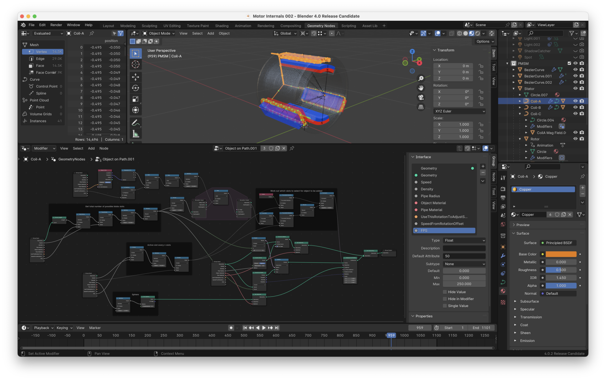
Most of the work for this animation is done in Blender, with Final Cut Pro just doing the compositing (I really should learn how to do that in Blender).
The bulk of that Blender work was in:
- Animating the “blobs” that show stator winding current flow (Geometry Nodes, see image below)
- Stator winding magnetic field animation (Geometry Nodes)
- Force vectors showing Stator magnetic field to Rotor permanent magnet field (Geometry Nodes)
Stator Currents
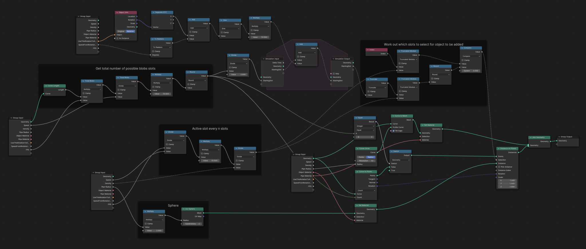
This Geometry Nodes setup is based on one I’ve used before. There are probably way better ways of doing this but the basic concept is to:
- Resample a curve and assign it a number of “slots”. This is the total number of positions that a blob can appear at.
- Then work out which slots should have a blob for any given frame
- For this animation I used the new Simulation Nodes concept to add/subtract movement of the blobs per frame, which allowed for a smoother animation as the speed of the current changes over time.
Stator Magnetic Field
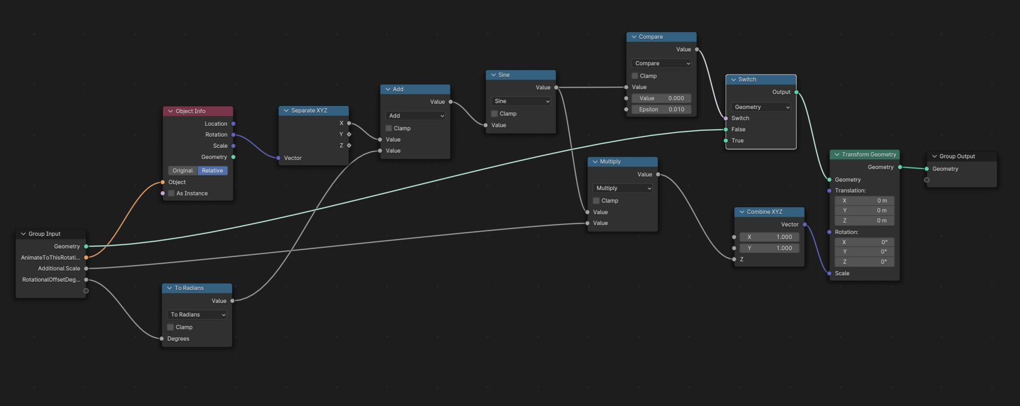
Simple Geometry Nodes map to take the Rotor angle and map it to the scale of the Stator Magnetic Field mesh. The mesh was modelled by hand.
Force Vectors
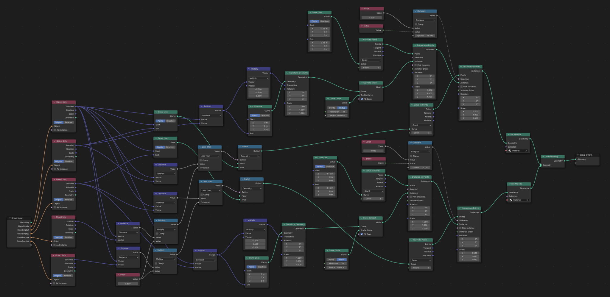
This one was tricky. The Geometry Node setup use a bunch of empties.
- Three empties placed in the middle of the stator coils
- Two empties placed in the middle of the rotor magnets, parented to the rotor
- The GN setup then works out the distance between the stator empties and the rotor empties, and creates vectors between the empties.
- Straight line “Curves” are instanced on the vectors centre point (index 1 or 0,1,2)
- Lines are then instanced at the centre of the vectors and thickness applied.
I also created a version of these force vectors with arrows at the end of each vector. But…. that really needed the arrows to point in the force direction and I was out of time to figure out how that could work. And of course it would be good to colour code the forces directionality too.

Leave a Comment