
Excuses, Excuses
Ok… so… I’ve been distracted.
Since starting this EV conversion project I’ve got a bit distracted by a couple of other projects. The first was the Caterham and Lotus Seven Club, in general and specifically the move to the new website. But I also found I was getting involved in way more other stuff and that was taking up time.
So, as of the end of 2023 I resigned my post with the club and that free’d up a bunch of time.
Then I got the YouTube bug. Since releasing the kick-off video for this project last year, I’d been meaning to do a series of “explainer” videos that went into some of the technical background to this project. The first is/was about the differences between AC and DC electricity used in an EV, and then there were going to be a bunch of videos about the components used in an EV.
In the end this series has been condensed down into two videos. But they have taken me 100’s if not 1000’s of hours to finish. I ended up doing hundreds of animated clips for the videos, showing all sorts of stuff that I should have glossed over. And there’ll be a few blog posts about them coming soon too.
But I’m very nearly finished with those videos and so I can get back to some more progress stuff…. Some of which I’ll blogging about a bit more here.
And the first of those Putting the EV in Seven (PTEVIS) blogs I need to catch up on is a task that I actually did last summer (2023). Scanning the project car.
Why Scan My Car?
It was always my intention to scan the car and to therefore get a millimetre accurate “digital twin” of it. This would greatly help in the space planning of the conversion (removing a lot of the other form of CAD – Cardboard Aided Design, where we mock everything up with cardboard (not without its merits by the way)). And because Sevens are renowned for being of varying dimensional repeatability, this would allow me to get my chassis accurately dimensioned.
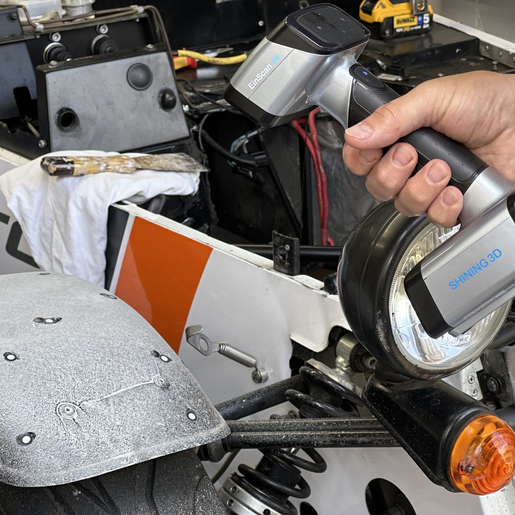
NB: Since getting more proficient with the scanners I own, if I’m measuring anything bigger and more complicated than a brake disc, then I’ll scan it rather than reaching for a tape measure. A scan can deliver mm accuracy and, crucially, nail down geometry that would be almost impossible to capture with a tape measure, pen and paper. I have a couple of 3D scanners, one expensive, and one very expensive. The expensive one (Shining 3D Einstar) cost about £1,000 and can provide scans that are easily good enough for home-hobbyist garage work… Highly recommended if you have the time, money and computer knowledge to take advantage of one.
For those interested, my very expensive scanner (at least in my terms) is a Shining 3D HX. I should probably write a blog post about the two scanners when I get a chance.
If I do, I’ll try and put a link to it here.
Preparation for Scanning
The first part of the scanning process was to get the car into a state where the scan would have the right stuff left on it that I wanted to have a scan of, and so that meant removing the project car’s Ford Sigma engine, Caterham six speed box and fuel tank.
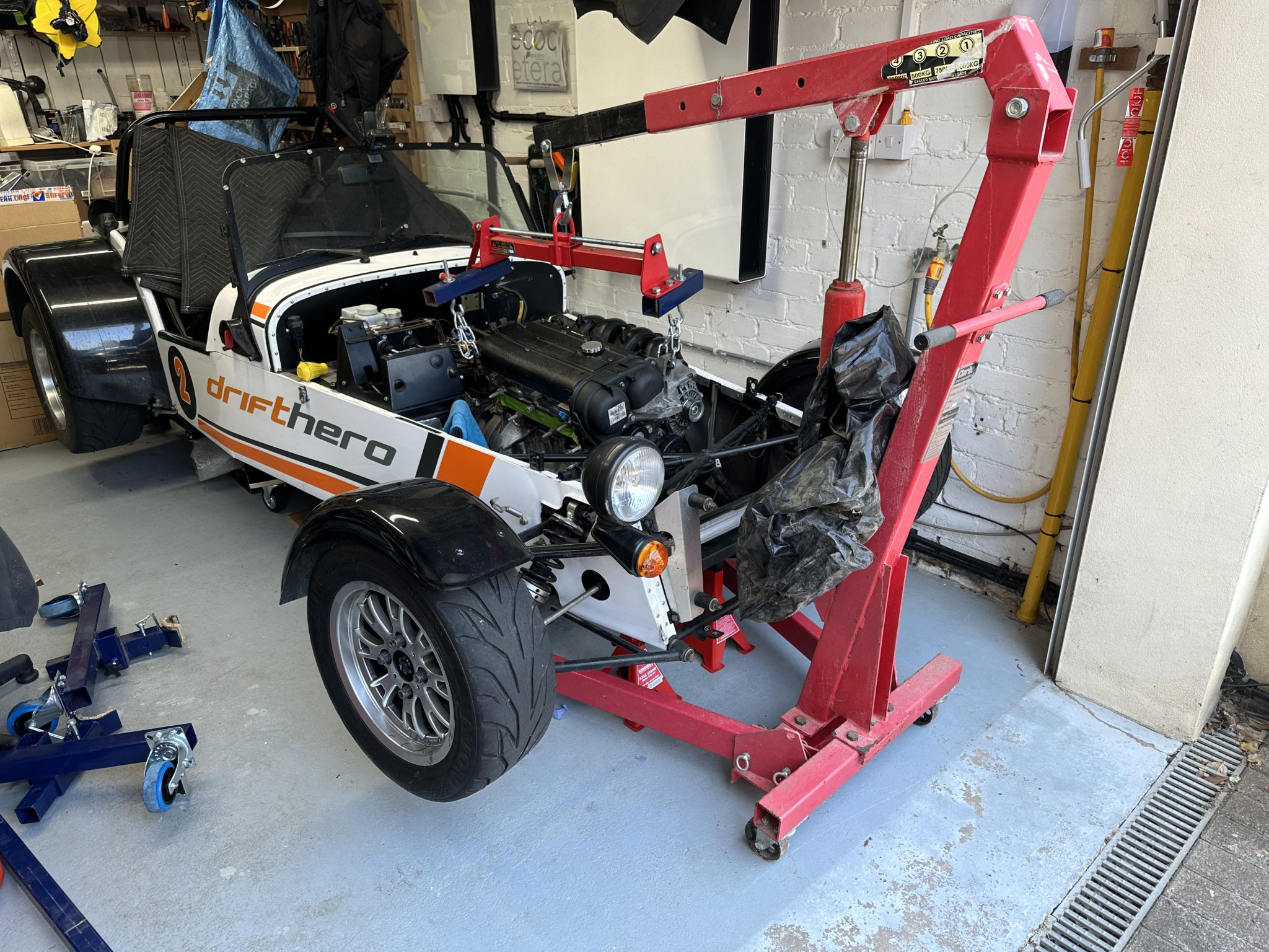
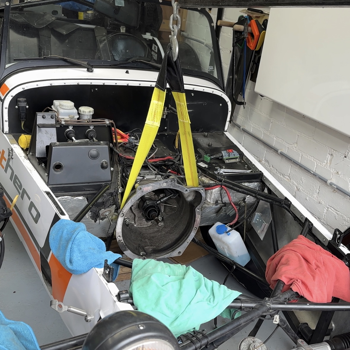
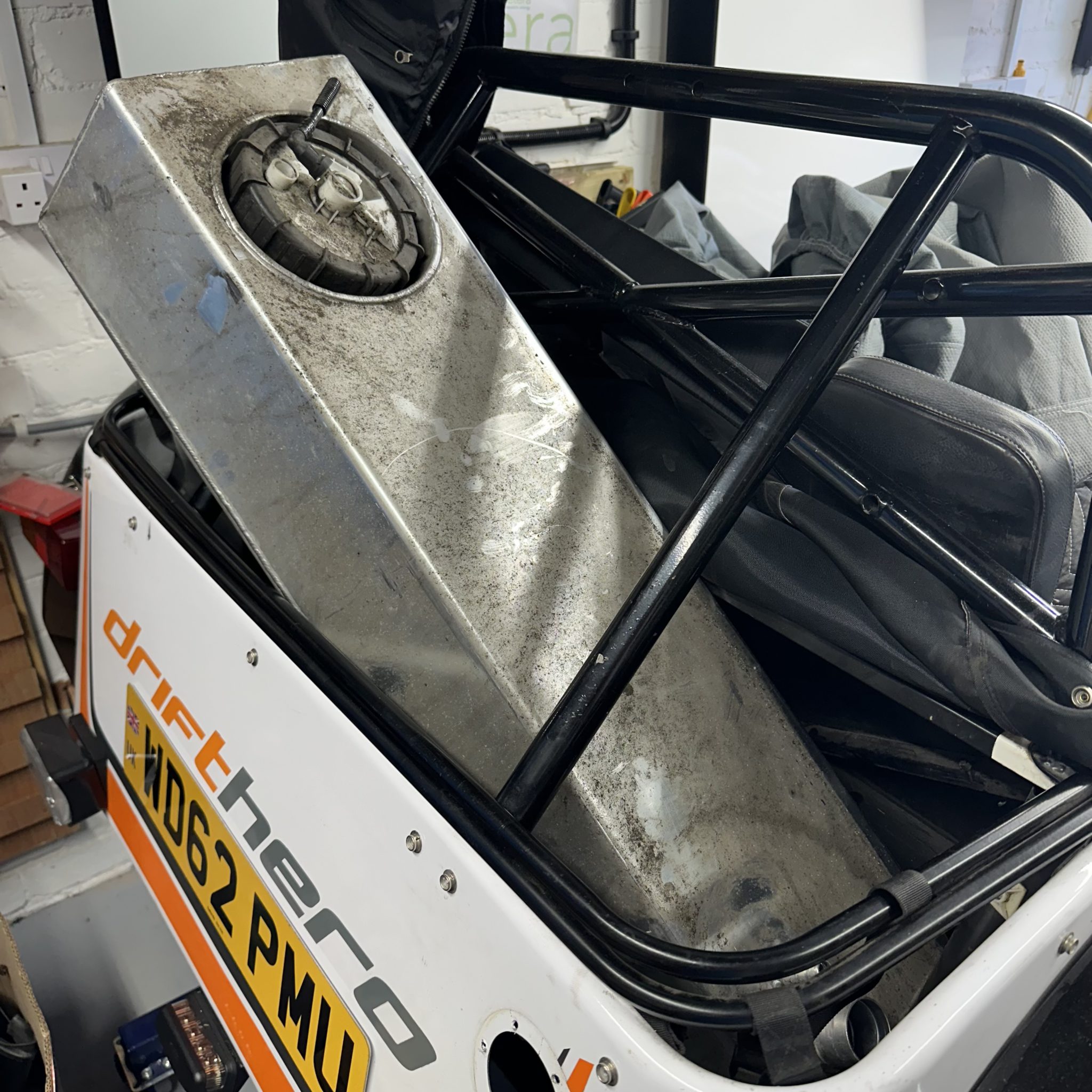
All were duly removed and moved on to club members who have a better need for them than I.
The engine and gearbox came out pretty easily and seemed to be in pretty good shape. Even though this ex-drift car had probably spent most of its life sat at its rev limiter in first, it had at least been kept out of the weather. The seats and bodywork have seen better days for sure, but the mechanical side of the car seemed to have been kept in good shape.
With those two major components gone, that left what I thought would be the main remaining project components: chassis, prop, diff and half-shafts. At this point I also took the scuttle off the car again so I could get a better look at the electrical side of things, as this was going to get a major overhaul.
See this post about how I made the scuttle easily removable with 3D printed nut holder widgets.
Now for some scanning tips.
Scanning Tips
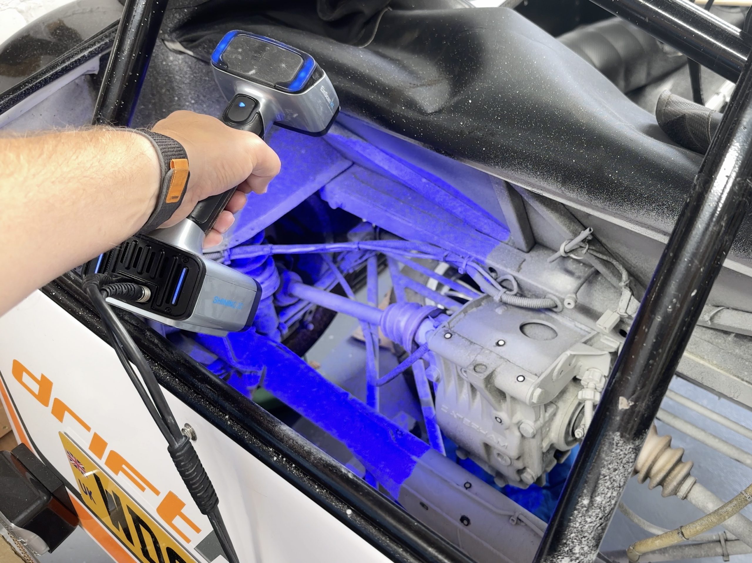
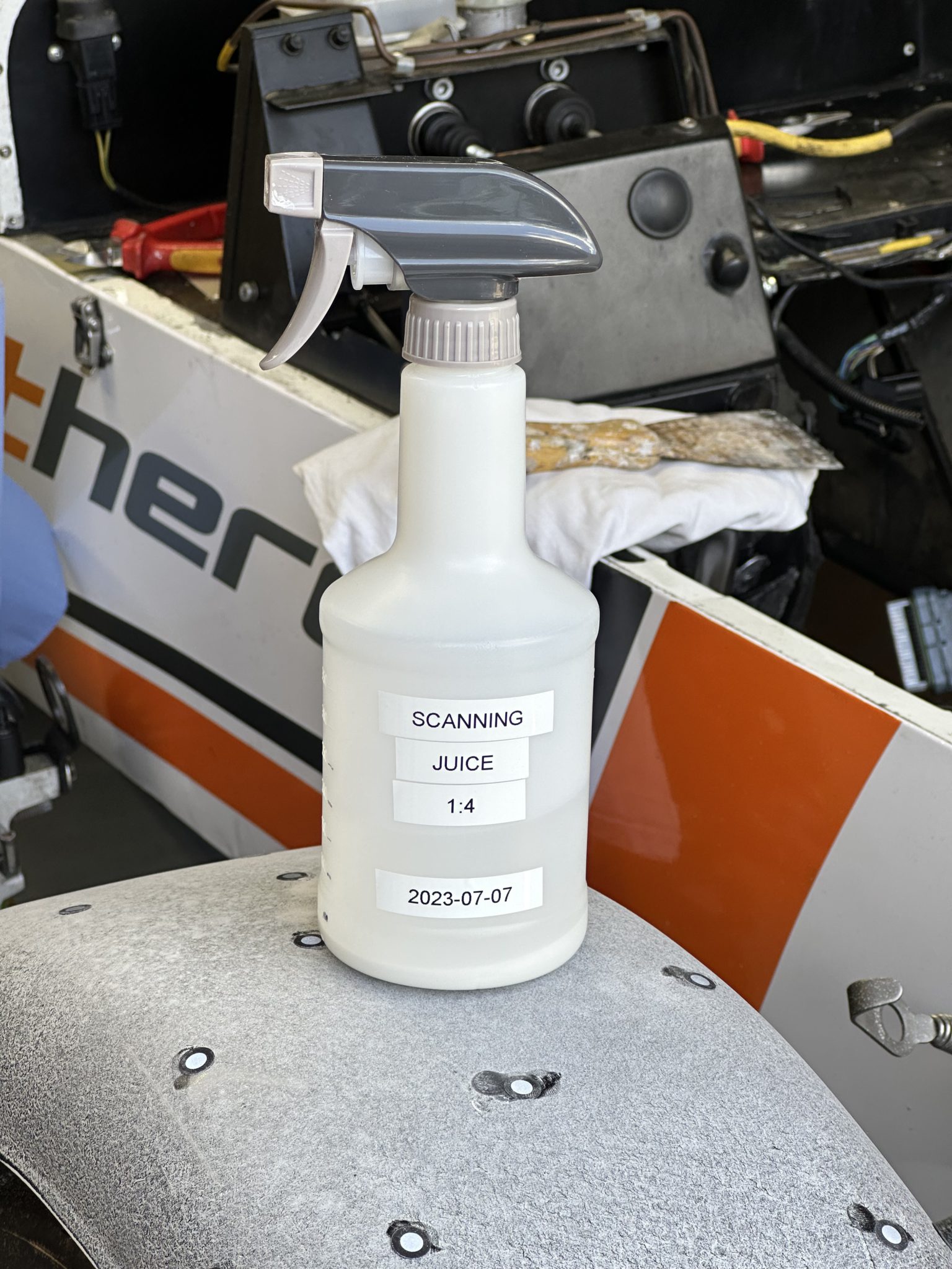
Scanning TIP1: Scanning Juice
This was going to be the largest thing I’d scanned to date. And I was going to have to work on my “work flow”, which started with surface preparation before even getting the scanner out of its box.
Having watched a lot of YouTube videos on scanners and scanning, and already scanned lots of other stuff myself, I knew that scanning can be a fickle thing. One YouTube channel I really like (SuperfastMatt) had suggested using a concoction he’d also seen recommended and which I came to term “Scanning Juice”.

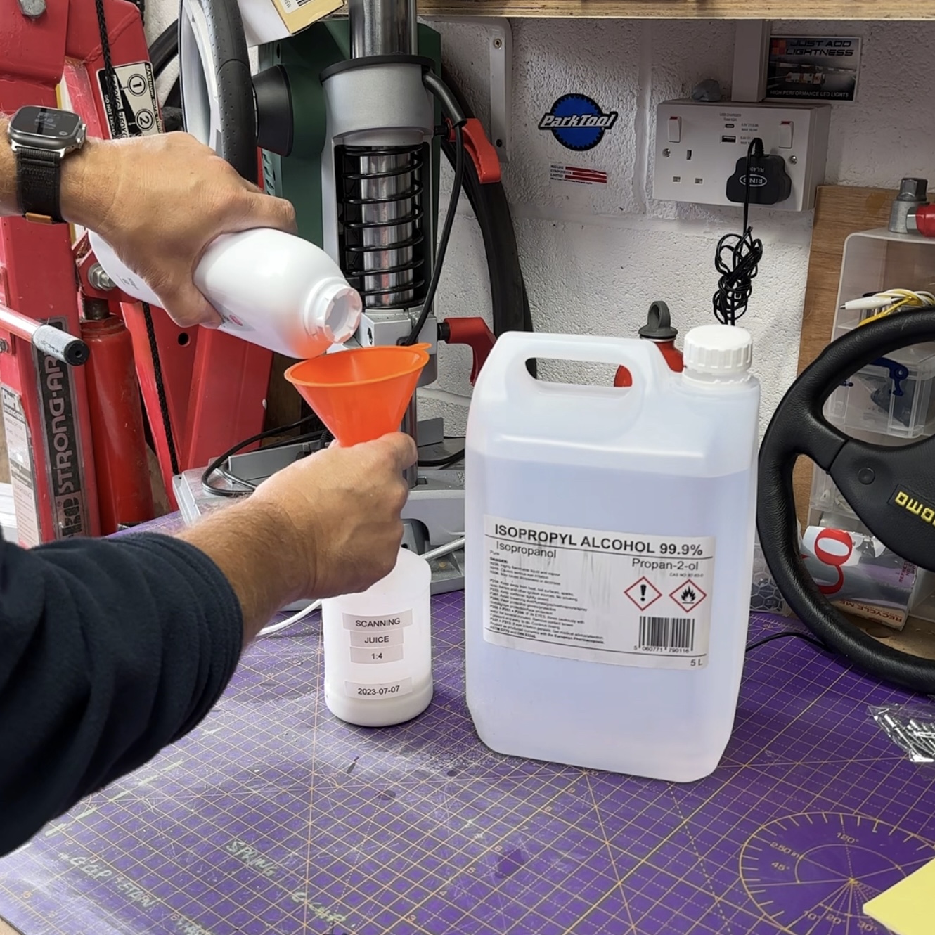
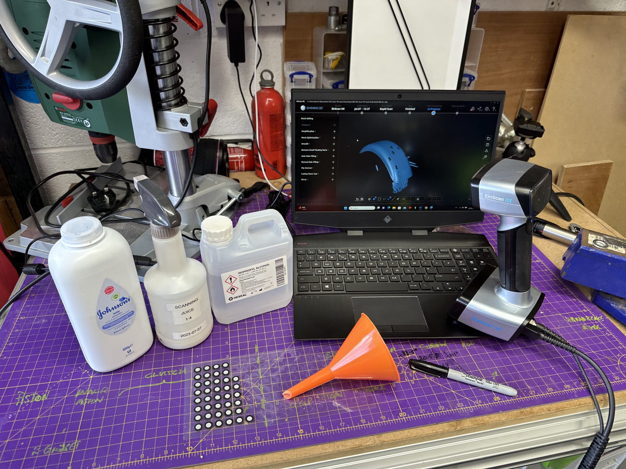
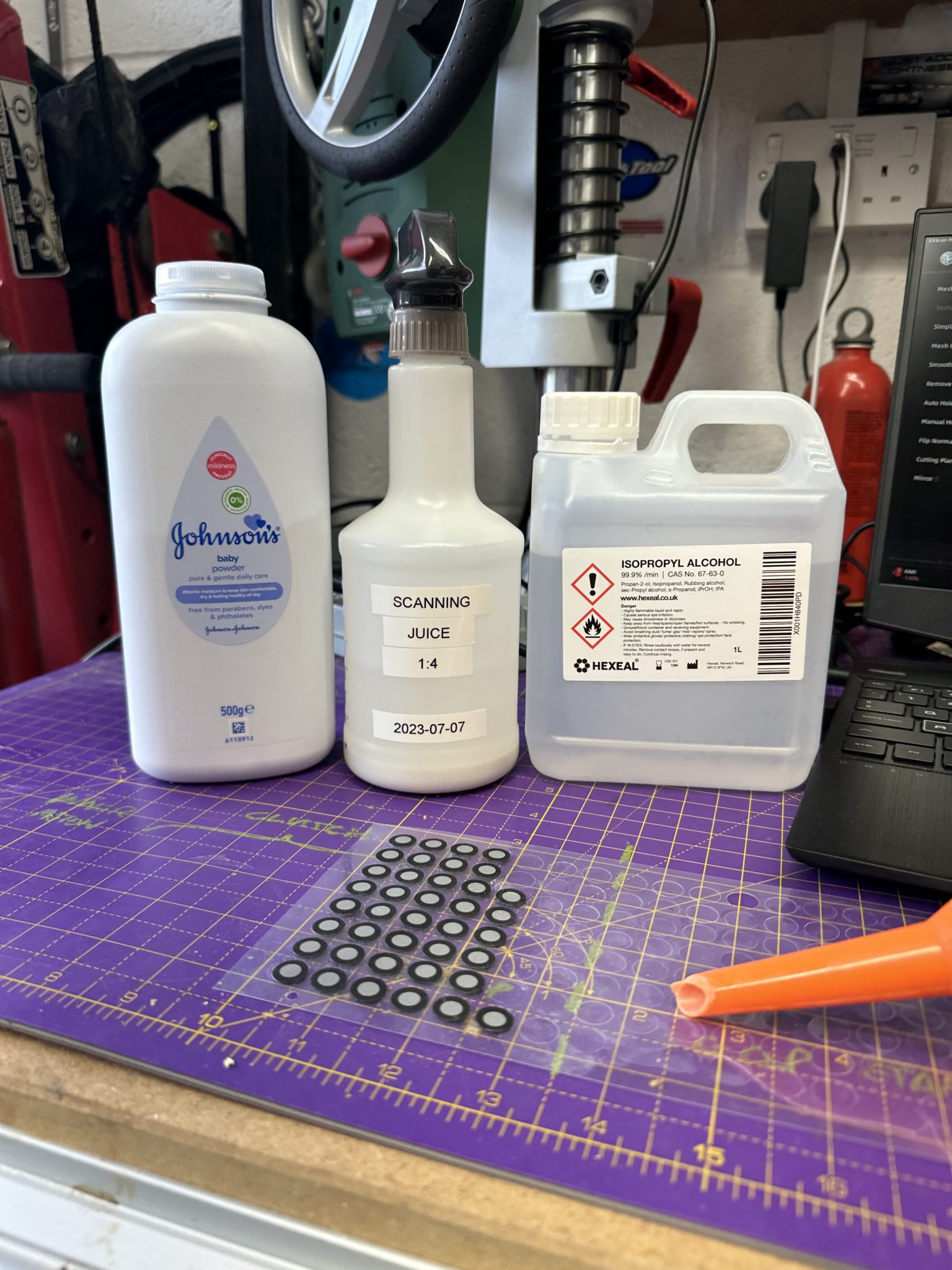
This simple solution is mixed up as four parts isopropyl alcohol to one part talcum powder (at least the garage smelt nice!). This is then sprayed onto anything that needs scanning, so the scanner can get a good lock on the surface details – black surfaces are bad, shiny surfaces are bad, black and shining (like many Seven parts) are really bad. Covering them in a film of talcum powder really helps the scanning process after the alcohol has evaporated.
Applying a liberal coating of the juice left a solid matt white surface that turned out to be really good for scanning.
Workflow Tip2: Scanning Dots
This tip was also hard earnt watching endless YouTube videos…. Large flat surfaces don’t scan well… even with scanning juice.
In addition to having internal inertial measurement (IMU), 3D Scanners work in a couple of ways to track what they’re looking at. They can use their IMU to keep a reasonable track of where they are in space, but also rely on either feature alignment or tracking dots. Feature alignment can work well when three’s lots of detail in the field of view of the scanner but struggle with large flat surfaces (like car body panels) where there isn’t many contours to track against.
Send in the scanning dots. To get over this lack of details in the scanner’s field of view, you attach lots of small reflective dots to the object you’re trying to scan. The recommendation is that there should be at least 4 dots in the scanners view at any one time. I found that 4 was actually a minimum number of dots the scanner needed to see before it could get a good lock the subject.
You also need to make sure the dots are randomly placed. If you laid them out in an array, for instance, then the scanner wouldn’t be able to differentiate one section of the array from the another.
There’s an additional benefit to adding all these dots – when you get to the later stages of a full scan, when you’re trying to stitch multiple scans together, the scanning software can use the dots to combine all the scans into one aligned composite scan.
Workflow Tip 3: Accept You Need Multiple Scans
Perhaps this is obvious but you’re not going to be able to scan a whole car in one go.
There’s a couple of points to remember here:
- Scanning isn’t always reliable. You may get into a long scan only to find that the scanner has lost where it is and its dumping bad scan data into the session. This can be a real pain to remove. So shorter sessions means its not such a big deal to scrap the session and start again.
- Unless you’re a black-belt in yoga, you’re not going to be able to reach all the parts of the thing you’re scanning in one go. If you try and get too much in one scan part, then you find the scanner can struggle to keep tracking as you try and fold around a weird piece of geometry you’re trying to scan. I found that I needed to scan bits of the car from above, below and from various other side-on angles. It’s better just to accept that each of these is a different scan and then you can position yourself to be able to take the best scan you can.
- Try some sample scans out before you do it in anger. There were bits of my car that I really struggled to scan. For instance trying to get a clean scan of the differential, I could scan the top, and scan the bottom, but getting a scan that incorporated overlapping geometry from the two scans was difficult. More scanning dots helped here for instance… so the stitching algorithms could lock onto the edges of the scan and know where they were in relation to the other scans.
Workflow Tip 4: Scan more than you need
It’s tempting to get frustrated with all this scanning and to stop at what you think is enough data. I found I almost always got back to the computer to find I really needed another set of geometry.
It’s also a good idea to leave the subject with all its scanning juice and dots left there for as long as possible. If you want to stitch a subsequent scan into an existing project, then you really need to have all the scanning dots located where they were in the original scan… and because they need to be placed with mm accuracy, you’re not going to be able to replace them where they were if you’ve removed them all.
This tip also includes scanning as many angles as possible of the geometry you’re capturing. So if you’re trying to capture all the chassis tubes then get scans from both the top and bottom… that’ll really help when you’re trying to recreate the structure in a CAD package later. .i.e you can make a reasonable assumption about the diameter of a round tube when you have 120 degrees scanned from the top, but its much easier to get its diameter and location along its length if you have scans from the top and sides.
Workflow Tip 5: Go Slow
Obvious really, but set aside plenty of time for your scans and don’t try and rush them. You’ll only get trash data
Post Processing
Now you’ ve got a bunch of scans, you’ll need to post process them. A lot of this will be dependent on the software you’re using (I was using Shining 3D’s Einscan software for the HX) and so I won’t go into detail here, just give some tips I learnt and that are probably very generic.
Post Processing 1 – Clean-up The Scans
This is an obvious one, but you certainly need to get rid of all the “floaties” that will probably have been created in the scan. Scanning will often create small floating bits of geometry that can be easily removed.
In this step you’ll probably also want to get rid of any bits of ground, bench, table etc that have been included in the scan. Sometimes it can help to keep them if you’ve got scanning dots located on them, but for the most part you need to remove these elements first.
Post Processing 2 – Stitch It Together
Once you’ve got a bunch of clean scans then you need to stitch them together. There are loads of good YouTube videos on this and I’d recommend: SuperfastMatt, Learn Everything about Design and Making for Motorsport.
Post Processing 2 – Align to Co-ordinate System
This one’s important – align your composite scan to a co-ordinate system as early as possible. Make sure your scan verticals are upright in your co-ordinate system and that whatever you think of as front on your subject is aligned to one other co-ordinate. I like my verticals to be aligned to the Z axis and the front of the car to aligned to the X axis.
I made the mistake of thinking I could get my composite scan aligned later on in my post processing workflow. I should have used the scanning software to align my scan correctly – it caused me a lot of problems later, not least of which trying to add further scans to the composite.
Post Processing 3 – Separate Parts
That probably gets you to the point where you’ve exported your composite scan from your scanning software. At this point I imported my scan into Mesh Mixer.
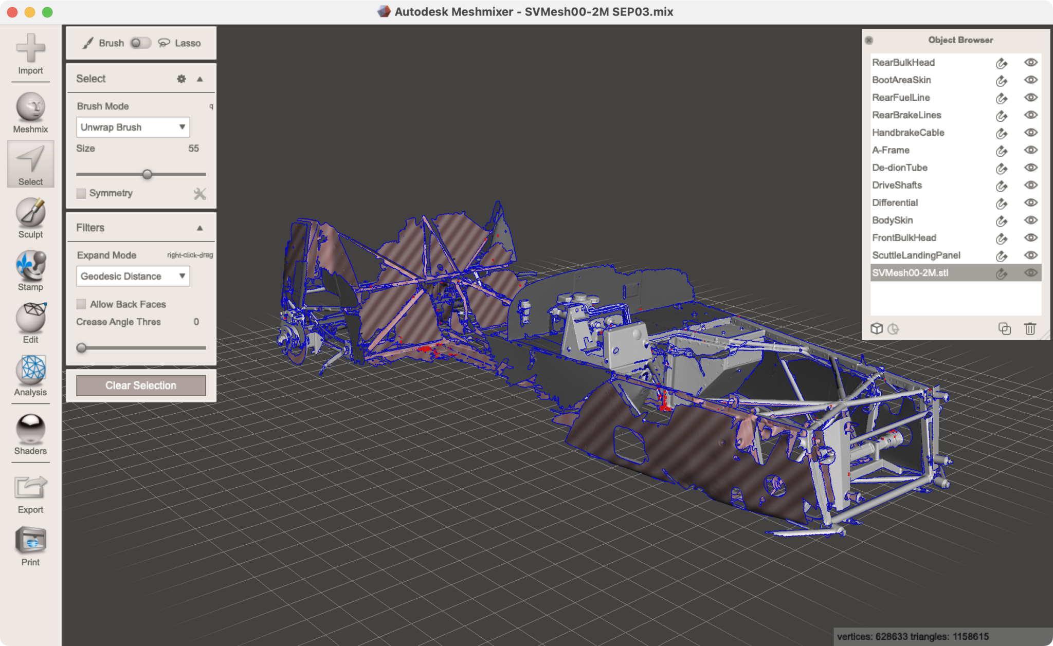
Mesh Mixer has been bought by AutoCad and in theory you’re supposed to use Fusion 360’s mesh tools to edit your scans. But Autodesk have dropped the ball on this and the now unsupported Mesh Mixer is still way better at editing meshes than Fusion.
Once the scan is in Mesh Mixer then I used the selection tools to chop the scan up into different parts – for me that was: chassis, differential, prop-shaft, drive-shafts, break lines etc. It meant that when I was space planning later, I could hide various components to give clarity to what remained. This was a huge help.
Post Pricessing 4 – Reduce Poly Count
Finally on post processing. At this stage you can use Mesh Mixer to reduce the poly-count. I saved off the high-poly models so I could come back to them later. But I found that reducing the polygon count of what I brought into my CAD package later really helped with redraw times there.

Leave a Comment