
As part of my Putting The EV in Seven project, I decided I needed a big detour into suspension travel on a Seven. That sounds like a good route to getting my project finished quickly, right?
Well, it goes a bit like this.
In a non-linear-timey-wimey sort of way of looking at the PTEVIS project, I’m actually a lot further down the road than recent posts here would seem to imply. There’s lots that’s happened and that I’ll get to (eventually). But for the moment you just need to know that I need to know how much suspension travel a Seven can have. It’s to do with needing new drive-shafts that we’ll get into… all in good time.
I made a few posts on the Caterham and Lotus Seven Club forums, asking people if they knew how much suspension travel a Seven has in practice and the only sound coming back was that of tumble weed. I also asked people who probably ought to know, but they didn’t.
So, the only sensible thing to do was to work it out for myself.
I had a couple of suggestions about putting a cable tie around the inner shaft of a suspension damper and seeing how much it moved after driving around for a bit. That’s a good way of finding the maximum compression, but not so good at working out extension and compression.
And because I’m a software and electronics sort of person, I decided I needed to “instrument” my suspension in the most complicated way possible.
I just needed to come up with a bunch of complicated electronics, software and stuff… drive the car around the billiard table top smooth Bristol streets for a bit and that should tell me how much suspension travel I could expect.
Now, in the interests of presenting this project in a mostly chronological order I’m going to explain what I did and then present the results. So if that’s not in line with your eagerness to see the fruits of my labour, and frankly you find all the tech stuff too boring (I know a lot of people just look at the pictures I post and not the words ¯\_(ツ)_/¯ ), then please skip to the bottom of this post.
The Nuts and Bolts
So my solution is going to be a mixture of some prototype electronics boards, software to control them and some 3D printing and rubber bands to make it all stick.
The Concept
The concept behind this mini-project is that I’ll measure the suspension travel using some electronics that will measure the distance of some static part of the car to some other part that’s attached to the moving suspension on the car.
In the end this meant I would attach a sensor to the car’s chassis (which is the sprung mass) and measure the distance to the top of the de-dion tube ears (the unsprung side of the equation).
Electronics
I’ve been a big fan of Limor Fried (LadyAda) and her company Adafruit. She/they make and sell a bunch of neat electronics, ostensibly for “makers” and for teaching, but I really like the stuff for throwing a project together without needing to do a whole bunch of electronic board design.
Adafruit support a couple of different ways of programming these boards and we’ll come to that in the Software section below.
Taking that love for all things Adafruit a bit further, I generally settle on using their Feather and FeatherWing products. All these boards are designed to a standard 0.9 x 2.0″ form factor. The core of the boards are the processors that you can stack with sensors, displays, LEDs etc. You can also add all the boards you want to a base prototype board and have all the connection signals connected up automagically. That’s what I did.
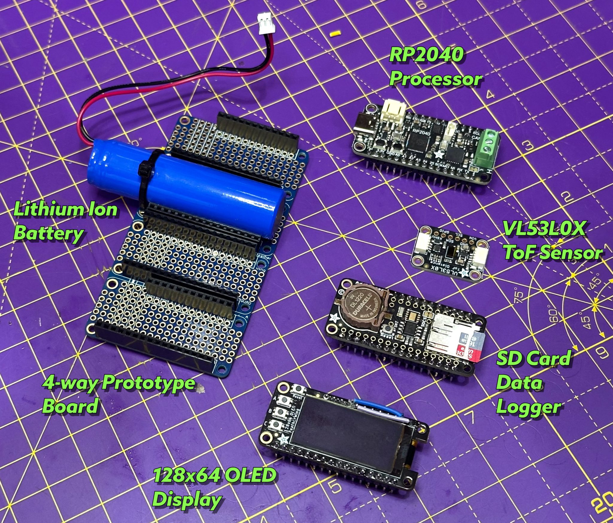
After a bit of searching around the Adafruit site I settled on one of the relatively new Raspberry Pi RP2040 embedded processor boards (I’m using them elsewhere on my project), an SD card based logger and a display. The sensor that will measure the suspension travel is a Time-Of-Flight VL53L0X I2C board. The fact its not a Feather is fine, that means I can have the expensive, sensitive, main electronics sat in the boot of the car and the sensor connected on a flying lead to somewhere near the suspension mucky bits.
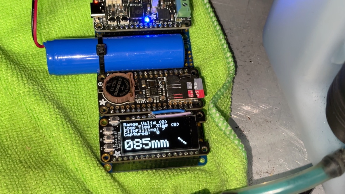
Because I can house the electronics in the boot (trunk), it also didn’t need to be particularly compact. I therefore ended up with this board setup…
The battery is way over the top for what I needed, but it was what came to hand first.
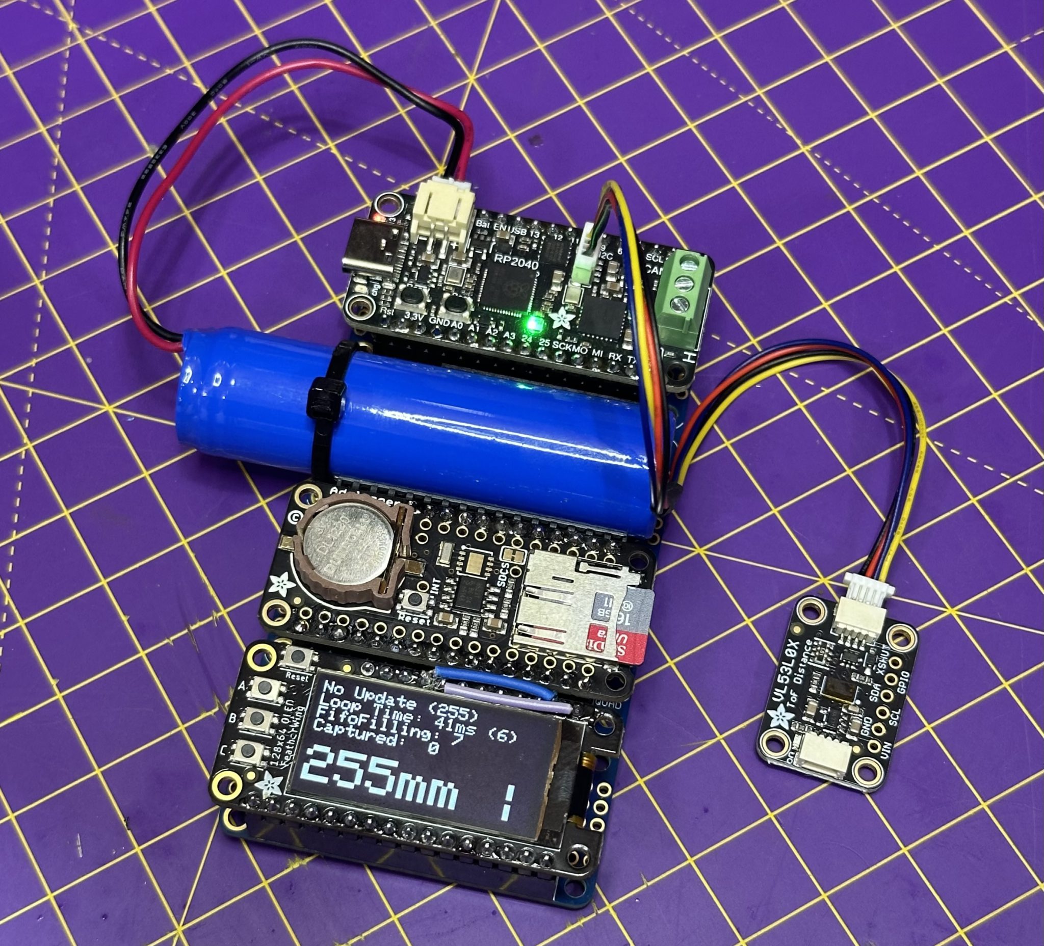
The buttons on the OLED display were set up to:
- A – Start and stop capturing
- B – Print SD Card directory listing
- C – Prints out the contents of the last data file
One area that took a bit of fiddling was I2C interfaces on the system. The ToF sensor and the OLED display both used I2C as their primary interface to the processor. However, because I wanted Core0 to access the display and Core1 to talk to the ToF sensor (see software section below), I ran into problems. With the two cores trying access one I2C bus, the code wasn’t thread-safe and the two cores would overwrite each other.
To fix this problem I rewired the I2C interface on the OLED display to use the second I2C interface of the RP2040. This got me scratching my head for a few nights on the sofa, but in the end the problems were of my own making… I’d wired up the OLED with 5V connected to one of the I2C ports and that blew up the OLED board, which took me a while to realise.
In the end WIRE and WIRE1 interfaces worked fine, even though I’d convinced myself that the RP2040 BSP wasn’t working… it was!
Software
The code for this project was written in the Arduino programming paradigm. It is possible to use Circuit Python on these RP2040 boards but after testing it out I found:
- Circuit Python couldn’t be multi-threaded. At least I couldn’t find a way of doing it. Arduino-C has support for the RP2040’s dual cores and a simple FIFO communication system to send 32bit values between the two cores.
- A quick test app using Circuit Python could only manage about 10 samples of the ToF sensor a second. Switching to Arduino-C
So, the code was written in Arduino-C, using the Setup(), Loop(), Setup1() and Loop1() functions to get dual cores running.
Core0 was set to do:
- Display status information on the OLED
- Take input from the OLED board buttons
- Communicate with the host on the serial port
Core 1 was then used to:
- Interact with the ToF sensor
- Send data and status from the Sensor to Core0
I’ve included the full listing of the code at the bottom of this post. It’s not pretty, but it worked!
Below is a short video of me waving my hands over the top of the ToF sensor.
Mechanical
And now for the physical stuff. The electronics was going to sit in the boot and the sensor was going to attach to the chassis. I was also thinking that the sensor might need a nice bright surface to be pointed at to get good results.
So I was going to need a widget to connect the sensor to the chassis and possibly a bright flat surface on the de-dion suspension side of things.
Suspension Logger Chassis Mount
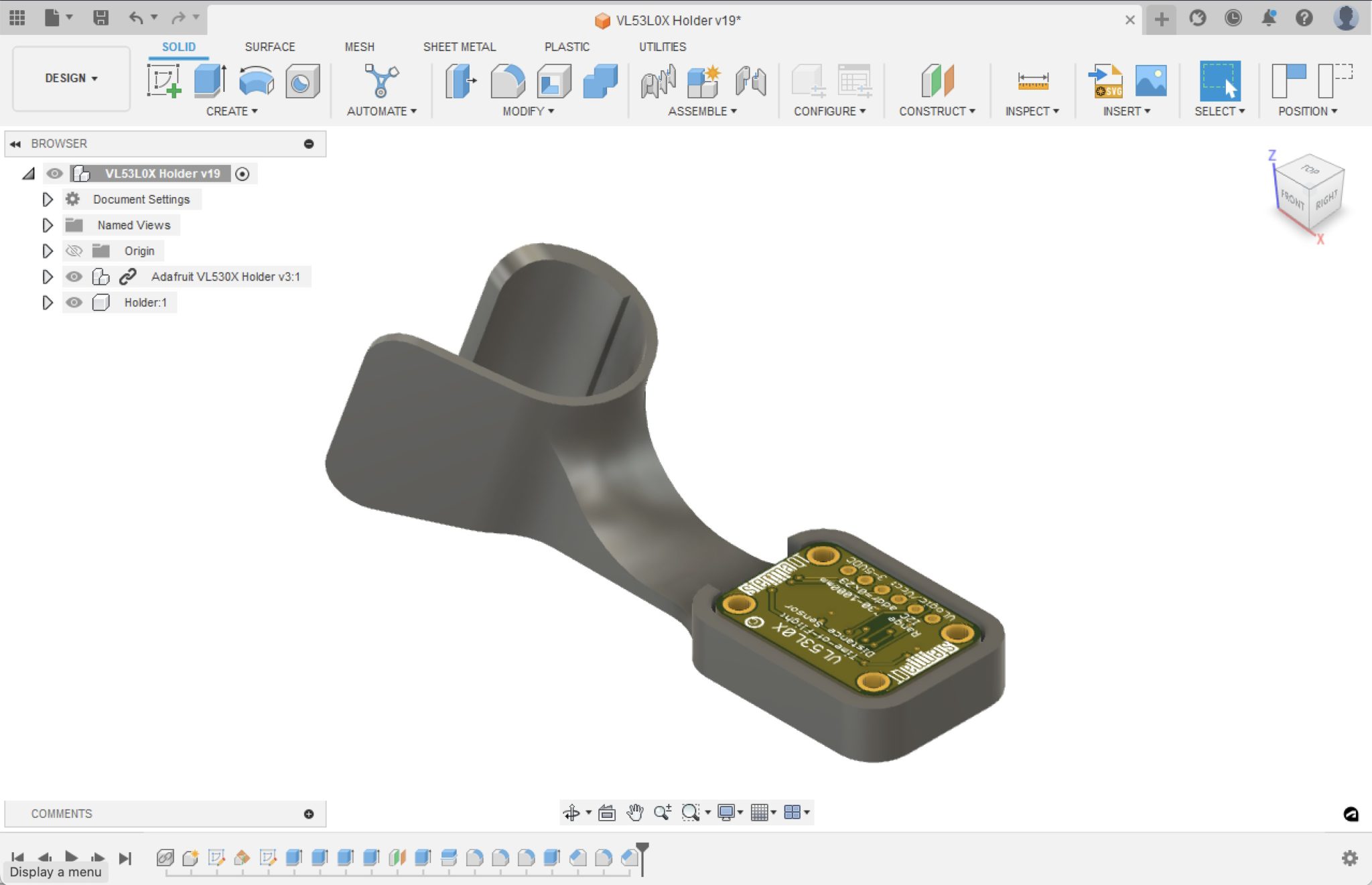
This is where I break out my laptop again and fire up Fusion 360. I’m a big fan of Fusion, and even pay for the full version, not the home version. Paying for the full enchilada means I have access to multilayer PCB design but also crucially I can have as many projects as I want stored inside Fusion-360’s cloud system – I have dozens upon dozens of Fusion 360 projects, so paying for the full version makes sense to me.
So I broke out Fusion 360 and modelled up a simple widget that would clip onto the car’s chassis rail in the rear wheel arch and would hold the ToF sensor.
I’m a big fan of the “fail fast” design methodology, so this widget wasn’t going to be an all singing all dancing sensor holder. I had no plans of taking the car out for data capture in the rain, or even when damp, so I could ignore making the widget water proof. It also only needed to sit on the car for maybe 20 or 30 minutes, so it didn’t need to be affixed in any permanent way, so I just made it snap on with an open back.
Installation
With all the design and coding done it was time to attach it all to the car and do some data logging.
It was at this point that I remembered I probably needed something bright and flat for the ToF sensor to ping its laser at.
I did install everything and turn it on. Only to find the ToF laser was picking a surface other than the one I wanted. So, being rather impatient, and accepting that this project is not really supposed to be taking this long, I cobbled something together in the garage with a clip from a kitchen baseboard assembly, a used food can, some cardboard and some tape…
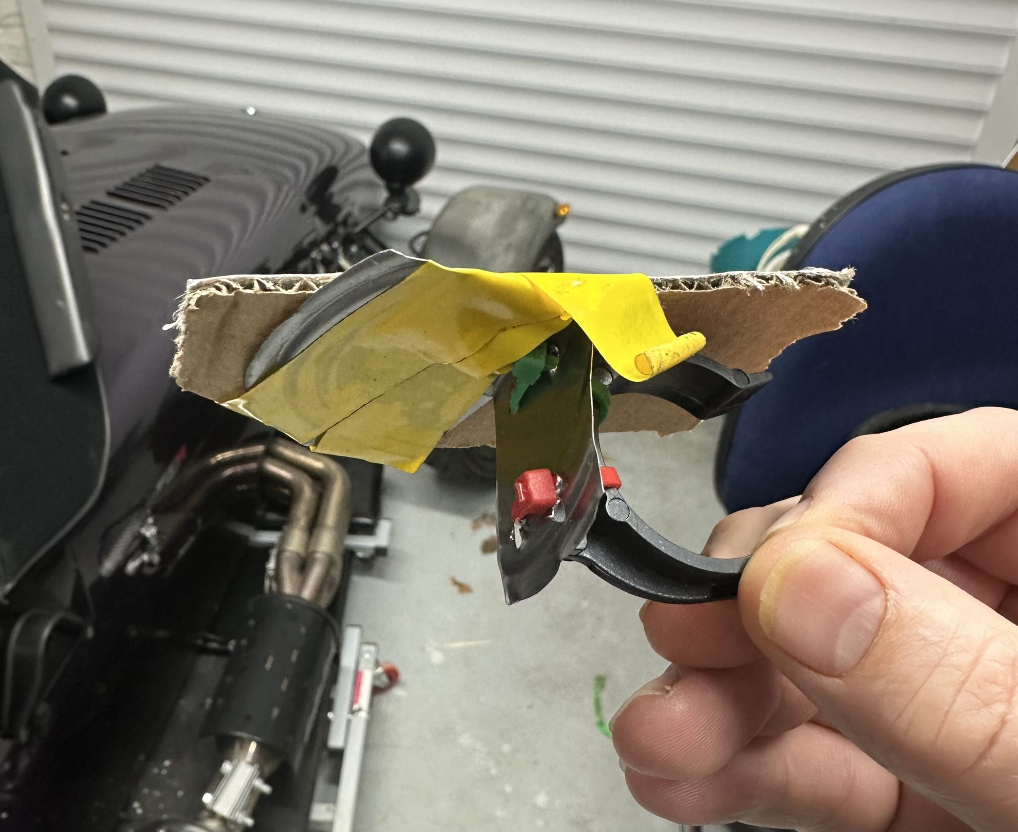
You can see I was not really inerested in aesthetics here. Fail fast. I just wanted to see if I could get something reliably reading of the ToF laser. And it did. So I left it alone – no need to over engineer anything, right!? I did try just cardboard attached to the kitchen clip, but it flopped around a bit and I thought it needed a bit more rigidity to not be the main source of measurement error!
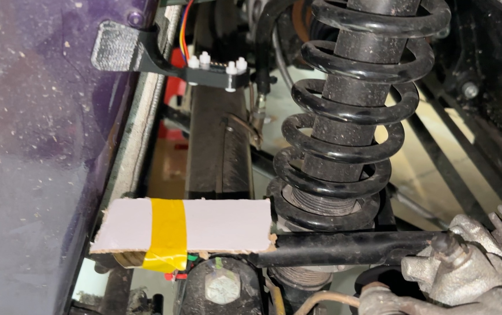
Here’s the laser target installed…
And here’s the board in the boot. I’ve laid it on a micro-fibre cloth – which is not as daft as it sounds. The electrical boards snag on the micro-fibres and with the cloth trapped in place, the electronics were well held in place. I did think about putting it all in a box, but as the saying goes… sod it, that’s good enough! 🙂
Results
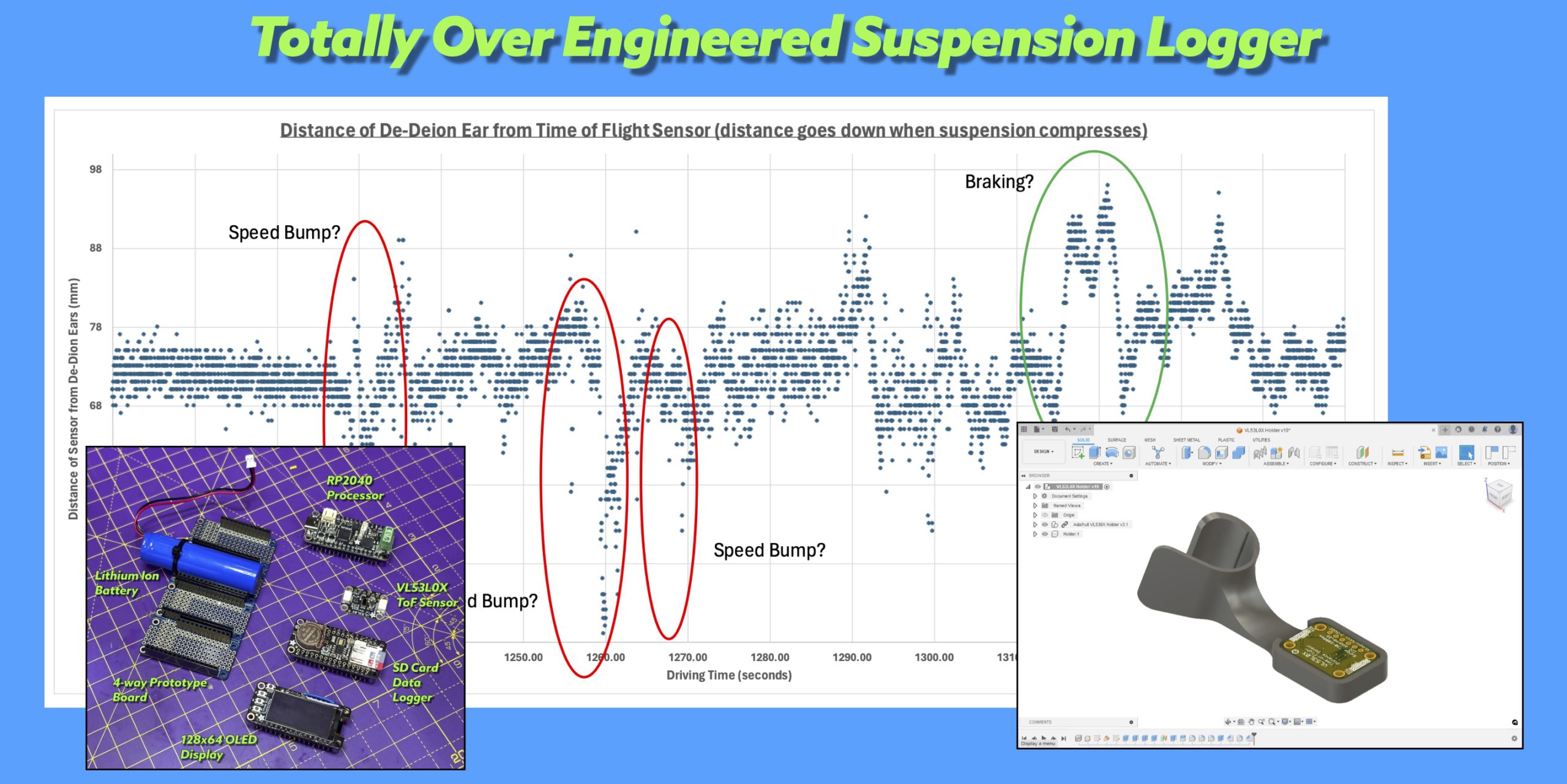
Here’s the image you want to see…
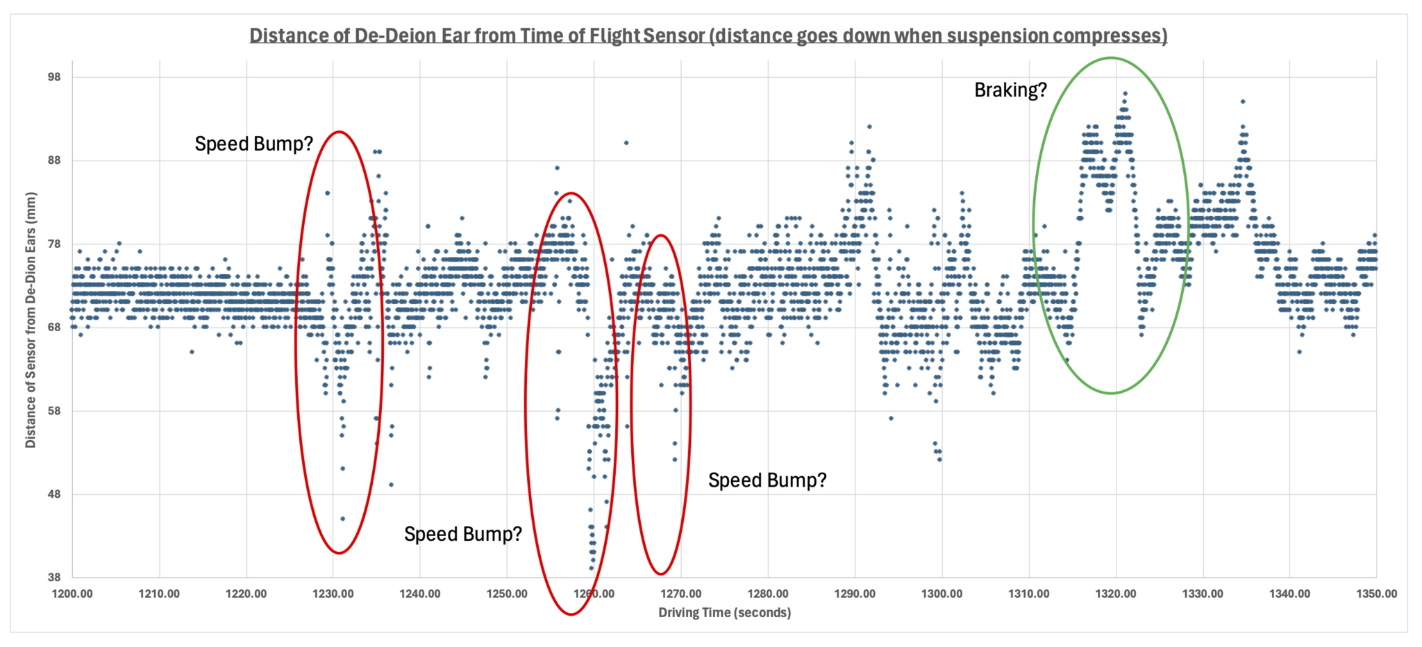
The plot above shows time on the horizontal axis and suspension travel on the vertical axis. The suspension travel is measured from the TOF sensor, so increasing numbers on the plot mean the suspension ears are moving downwards and decreasing numbers mean it’s moving up. The plot above is of a short part of a trip out in my 420R. The whole trip can be seen below… you can clearly see me getting into the car (twice) at the start, and then getting out at the end. The first plot is towards the end of the one below…
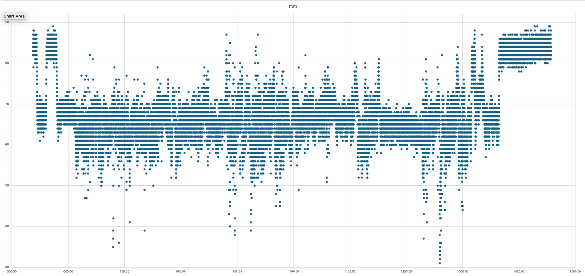
There’s clearly a lot of noise in the plots, but I got what I wanted out of it, and that’s the suspension compresses about 40mm and extends by about 20mm. I’m probably not a lot better off than the maximum allowable travel for the suspension which is +/-50mm, but it was worth this mini-project just to tell me that.
Wow! That was an awfully long post just to confirm what I think I already knew!
TTFN!
Suspension Logger Arduino Code
The code for this project is listed below. It’s not very pretty, but it did what I needed.
/*
 * Adafruit MCP2515 FeatherWing CAN Sender Example
 */

#include <SD.h>
#include <Adafruit_MCP2515.h>
#include <Adafruit_NeoPixel.h>
#include <Wire.h>
#include <SPI.h>
#include "Adafruit_VL53L0X.h"
#include <Adafruit_GFX.h>
#include <Adafruit_SH110X.h>

// OLED FeatherWing buttons map to different pins depending on board:
#define BUTTON_A  9
#define BUTTON_B  6
#define BUTTON_C  5

int led = LED_BUILTIN; // DANGER WILL ROBINSON... this is one of the SCL0 Pin too

#define CAN_CS_PIN    PIN_CAN_CS
#define CARDCS 10

// Set CAN bus baud rate
#define CAN_BAUDRATE (1000000)

#define MySDA0 12
#define MySCL0 13

Adafruit_MCP2515 mcp(CAN_CS_PIN);
Adafruit_VL53L0X lox = Adafruit_VL53L0X();
Adafruit_NeoPixel pixels(1, PIN_NEOPIXEL, NEO_GRB + NEO_KHZ800);
Adafruit_SH1107 display = Adafruit_SH1107(64, 128, &Wire1);

#define C0_DELAY (250)
#define LOX_SAMPLE_TIME (25)

int tx_count;
unsigned int block_start;
unsigned int c0_timer = 0;
char spinnerString[9] = "|/-\\|/-\\";
int spinnerCount = 0;
File root;

bool displayConnected = false;
bool loxConnected = false;
bool canConnected = false;
bool sdConnected = false;

void printDirectory(File dir, int numTabs, bool includeSubs) {
  while (true) {

    File entry = dir.openNextFile();
    if (!entry) {
      // no more files
      break;
    }
    for (uint8_t i = 0; i < numTabs; i++) {
      Serial.print('\t');
    }
    Serial.print(entry.name());
    if (entry.isDirectory()) {
      if(includeSubs) {
        Serial.println("/");
        printDirectory(entry, numTabs + 1, includeSubs);
      }
    } else {
      // files have sizes, directories do not
      Serial.print("\t\t");
      Serial.print(entry.size(), DEC);
      time_t cr = entry.getCreationTime();
      time_t lw = entry.getLastWrite();
      struct tm* tmstruct = localtime(&cr);
      Serial.printf("\tCREATION: %d-%02d-%02d %02d:%02d:%02d", (tmstruct->tm_year) + 1900, (tmstruct->tm_mon) + 1, tmstruct->tm_mday, tmstruct->tm_hour, tmstruct->tm_min, tmstruct->tm_sec);
      tmstruct = localtime(&lw);
      Serial.printf("\tLAST WRITE: %d-%02d-%02d %02d:%02d:%02d\n", (tmstruct->tm_year) + 1900, (tmstruct->tm_mon) + 1, tmstruct->tm_mday, tmstruct->tm_hour, tmstruct->tm_min, tmstruct->tm_sec);
    }
    entry.close();
  }
}

bool isCapturing = false;
unsigned long debounceTimeA = 0;
#define DEBOUNCE_TIME (200)
void buttonAISR()
{
  if (millis() > debounceTimeA) {
    if(isCapturing)
     isCapturing = false;
    else
     isCapturing = true;
    debounceTimeA = millis() + DEBOUNCE_TIME;
  }
}

bool doDir = false;
unsigned long debounceTimeB = 0;
void buttonBISR() {
  if (millis() > debounceTimeB) {
    if(!isCapturing)
      doDir = true;
    debounceTimeB = millis() + DEBOUNCE_TIME;
  }
}

bool doDump = false;
unsigned long debounceTimeC = 0;
void buttonCISR() {
  if (millis() > debounceTimeC) {
    if(!isCapturing)
      doDump = true;
    debounceTimeC = millis() + DEBOUNCE_TIME;
  }
}

void setup() {
  unsigned long now = millis();
  //switchDownTime = now;
  //nextDisplayTime = now;
  bool serialConnected = false;

    // set LED to be an output pin
  pinMode(led, OUTPUT);
  pinMode(BUTTON_A, INPUT_PULLUP);
  pinMode(BUTTON_B, INPUT_PULLUP);
  pinMode(BUTTON_C, INPUT_PULLUP);
  digitalWrite(led, HIGH);   // turn the LED on (HIGH is the voltage level)
  attachInterrupt(digitalPinToInterrupt(BUTTON_A), buttonAISR, FALLING);
  attachInterrupt(digitalPinToInterrupt(BUTTON_B), buttonBISR, FALLING);
  attachInterrupt(digitalPinToInterrupt(BUTTON_C), buttonCISR, RISING);

  debounceTimeA = millis() + DEBOUNCE_TIME;
  debounceTimeB = millis() + DEBOUNCE_TIME;
  debounceTimeC = millis() + DEBOUNCE_TIME;

  now = millis();
   // Wait to see if serial connects
  while (!serialConnected && (millis() < (now + 2000))) {
    if (Serial)
      serialConnected = true;
    delay(2);
  }
  //delay(500);
  Serial.begin(115200);
  //delay(500);

  // Now do the same for the NEOPIXEL
  pinMode(NEOPIXEL_POWER, OUTPUT);
  digitalWrite(NEOPIXEL_POWER, HIGH);
  pixels.begin();
  pixels.clear(); // Set all pixel colors to 'off'
  pixels.setPixelColor(0, pixels.Color(32, 0, 0));
  pixels.show();   // Send the updated pixel colors to the hardware.

  digitalWrite(led, LOW);   // turn the LED on (HIGH is the voltage level)
  pixels.setPixelColor(0, pixels.Color(0, 32, 0));
  pixels.show();   // Send the updated pixel colors to the hardware.

  Serial.println("** START **");

  Serial.printf("LED is on: %d\n", led);
  Serial.printf("BUTTON is on: %d\n", PIN_BUTTON);
  Serial.printf("NEOPIXEL_POWER is on: %d\n", NEOPIXEL_POWER);
  Serial.printf("NEOPIXEL is on: %d\n", PIN_NEOPIXEL);
  Serial.printf("SPI PINS MISO:%d, MOSI:%d, SCK:%d\n", MISO, MOSI, SCK);
  Serial.printf("CAN CS:%d\n", CAN_CS_PIN);
  Serial.printf("CARD CS:%d\n", CARDCS);
  Serial.printf("BUTTON-A: %d, BUTTON-B: %d, BUTTON-C: %d\n", BUTTON_A, BUTTON_B, BUTTON_C);
  Serial.printf("MySDA0: %d, MySCL0: %d\n", MySDA0, MySCL0);

  pixels.setPixelColor(0, pixels.Color(0, 0, 32));
  pixels.show();   // Send the updated pixel colors to the hardware.

  Serial.println("\nInitializing SD card...");
  sdConnected = SD.begin(CARDCS, SPI);

  if (!Wire1.setSDA(MySDA0)){
    Serial.printf("Failed to set SDA on Wire1\n");
  };
  if (!Wire1.setSCL(MySCL0)){
    Serial.printf("Failed to set SCL on Wire1\n");
  };
  //Wire1.begin();
  pixels.setPixelColor(0, pixels.Color(32, 0, 32));
  pixels.show();   // Send the updated pixel colors to the hardware.

  // Start the OLED Display
  //Serial.println("128x64 OLED FeatherWing test");
  delay(250); // wait for the OLED to power up
  displayConnected = display.begin(0x3C, true);
  if (!displayConnected){ // Address 0x3C default
    Serial.printf("Failed to start display\n");
  } else {
    Serial.println("OLED begun");
  }

  if (!mcp.begin(CAN_BAUDRATE)) {
    pixels.setPixelColor(0, pixels.Color(64, 0, 0));
    pixels.show();   // Send the updated pixel colors to the hardware.
    Serial.println("Error initializing MCP2515.");
    while(1) delay(10);
  }
  Serial.println("MCP2515 Ok!.");

  c0_timer = millis() + C0_DELAY;

  pixels.setPixelColor(0, pixels.Color(32, 32, 32));
  pixels.show();   // Send the updated pixel colors to the hardware.

  if (displayConnected) {
    display.display();
    delay(500);

    // Clear the buffer.
    display.clearDisplay();
    display.display();

    display.setRotation(1);

    // text display tests
    display.setTextSize(2);
    display.setTextColor(SH110X_WHITE);
    display.setCursor(32,0);
    display.printf("PURPLE");
    display.setCursor(32,16);
    display.printf("MEANIE");
    display.setTextColor(SH110X_INVERSE);
    display.setCursor(34,40);
    display.setTextSize(1);
    display.printf("Data Logger\n");
    display.setTextSize(3);
    display.setTextColor(SH110X_WHITE);
    display.display(); // actually display all of the above
    delay(250);
  }

  if (!sdConnected) {
    Serial.println("initialization failed. Things to check:");
    Serial.println("* is a card inserted?");
    Serial.println("* is your wiring correct?");
    Serial.println("* did you change the chipSelect pin to match your shield or module?");
  } else {
    Serial.println("Wiring is correct and a card is present.");
    // 0 - SD V1, 1 - SD V2, or 3 - SDHC/SDXC
    // print the type of card
    Serial.println();
    Serial.print("Card type:         ");
    switch (SD.type()) {
      case 0:
        Serial.println("SD1");
        break;
      case 1:
        Serial.println("SD2");
        break;
      case 3:
        Serial.println("SDHC/SDXC");
        break;
      default:
        Serial.println("Unknown");
    }

    Serial.print("Cluster size:          ");
    Serial.println(SD.clusterSize());
    Serial.print("Blocks x Cluster:  ");
    Serial.println(SD.blocksPerCluster());
    Serial.print("Blocks size:  ");
    Serial.println(SD.blockSize());

    Serial.print("Total Blocks:      ");
    Serial.println(SD.totalBlocks());
    Serial.println();

    Serial.print("Total Cluster:      ");
    Serial.println(SD.totalClusters());
    Serial.println();

    // print the type and size of the first FAT-type volume
    uint32_t volumesize;
    Serial.print("Volume type is:    FAT");
    Serial.println(SD.fatType(), DEC);

    volumesize = SD.totalClusters();
    volumesize *= SD.clusterSize();
    volumesize /= 1000;
    Serial.print("Volume size (Kb):  ");
    Serial.println(volumesize);
    Serial.print("Volume size (Mb):  ");
    volumesize /= 1024;
    Serial.println(volumesize);
    Serial.print("Volume size (Gb):  ");
    Serial.println((float)volumesize / 1024.0);

    Serial.print("Card size:  ");
    Serial.println((float)SD.size() / 1000);

    // This takes a lot of time...
    //FSInfo fs_info;
    //SDFS.info(fs_info);

    //Serial.print("Total bytes: ");
    //Serial.println(fs_info.totalBytes);

    //Serial.print("Used bytes: ");
    //Serial.println(fs_info.usedBytes);

    //root = SD.open("/");
    //printDirectory(root, 0);
  }
  c0_timer = millis() + C0_DELAY;
}

void setup1() {
  delay(2000);

  // Start the ToF Sensor
  loxConnected = lox.begin();
  if (!loxConnected) {
  } else {
    //Adafruit_VL53L0X::VL53L0X_Sense_config_t config = Adafruit_VL53L0X::VL53L0X_SENSE_HIGH_ACCURACY;
    Adafruit_VL53L0X::VL53L0X_Sense_config_t config = Adafruit_VL53L0X::VL53L0X_SENSE_DEFAULT;
    lox.configSensor(config);
    lox.startRangeContinuous(LOX_SAMPLE_TIME);
  }
  tx_count = 0;
  block_start = millis();

}

bool c0_timer_neo_on = true;
// CORE 0 LOOP
int range = 0;
int rangeStatus = 0;
unsigned int rangesThisTimer = 0, rangesLastTimer = 0;
unsigned int errorsThisTimer = 0, errorsLastTimer = 0;
unsigned int attemptsThisTimer = 0, attemptsLastTimer = 0;
unsigned int fifoFilling = 0;
bool fileOpen = false;  // Use another variable here so we don't get isCapturing being changed in ISR behind our backs
File captureFile;
unsigned int capturedCount = 0;
#define CAPTURE_FILE "capture"
#define FILE_EXT ".csv"

int findLastFileNameNumber(){
  root = SD.open("/");
  int fileNameNumber = -1;
  int fileNameNumberMax = -1;
  char fileName[256] = "";
  char fileRoot[256] = "";
  char fileExtension[16] = "";

  while (true) {
    File entry = root.openNextFile();
    if (!entry) {
      // no more files
      break;
    }
    sprintf(fileName,"%s",entry.name());
    //Serial.println(fileName);
    if (!entry.isDirectory()) {
      //Serial.println(fileName);
      if( sscanf(fileName, "%03d%s", &fileNameNumber, fileExtension) > 0) {
        if (fileNameNumber >= 0) {
          //Serial.printf("%d, %s\n", fileNameNumber, fileExtension);
          if(fileNameNumber > fileNameNumberMax)
            fileNameNumberMax = fileNameNumber;
        }
      }
    }
    entry.close();
  }
  root.close();
  return(fileNameNumberMax);
}

void loop() {
  int avail = 0;
  String outString = "";

  if(doDump) {
    uint8_t inputChar;
    unsigned int lineCount = 0;
    int captureFileNameNumber = findLastFileNameNumber();
    char captureFileName[256] = "";
    if(captureFileNameNumber <= 0) {
      Serial.printf("Unable to find a filename to read\n");
    } else {
      sprintf(captureFileName, "%03d%s", captureFileNameNumber, FILE_EXT);
      captureFile = SD.open(captureFileName, READ_ONLY);
      Serial.printf("Opened a file: %s\n", captureFileName);
      while(captureFile.available()) {
        captureFile.read(&inputChar,1);
        Serial.printf("%c", (char)inputChar);
        if(inputChar == '\n') {
          lineCount++;
        }
      }
      Serial.printf("We read %d samples\n", lineCount);
      captureFile.close();
    }
    doDump = false;
  }

  if (doDir){
    doDir = false;
    root = SD.open("/");
    printDirectory(root, 0, false);
    root.close();
  }

  if(!fileOpen && isCapturing){
    // Open a file for writing binary
    //SD.remove(String(CAPTURE_FILE) + String(FILE_EXT));
    char fileNameString[256];
    int captureFileNameNumber = findLastFileNameNumber();
    if (captureFileNameNumber > 0 ){
      sprintf(fileNameString, "%03d%s", captureFileNameNumber+1, FILE_EXT);
    } else {
      sprintf(fileNameString, "%03d%s", 1, FILE_EXT);
    }
    captureFile = SD.open(fileNameString, FILE_WRITE);
    if (!captureFile) {
      isCapturing = false; // This is a bit bad as it's changing the variable in another context than the ISR
    } else {
      fileOpen = true;
      capturedCount = 0;
      Serial.printf("Opened a file: %s\n", fileNameString);
    }
  } else if (fileOpen && !isCapturing) {
    captureFile.close();
    fileOpen = false;
    Serial.printf("Closed a file\n");
  }

  avail = rp2040.fifo.available();
  if(avail){
    if (avail > 2)
      fifoFilling++;
    unsigned int fromOtherCore = rp2040.fifo.pop();
    range = fromOtherCore & 0xff;
    rangeStatus = (fromOtherCore >> 8) & 0xff;

    // Now do something with the range data
    if(isCapturing && fileOpen) {
      outString = String(millis()) + "," + String(range) + "," + String(rangeStatus);
      captureFile.println(outString);
      capturedCount++;
    }
  }

  unsigned long colour = 0;
  if (millis() >= c0_timer) {
    rangesLastTimer = rangesThisTimer;
    rangesThisTimer = 0;
    errorsLastTimer = errorsThisTimer;
    errorsThisTimer = 0;
    attemptsLastTimer = attemptsThisTimer;
    attemptsThisTimer = 0;

    char spinnerChar = spinnerString[spinnerCount];
    spinnerCount++;
    if(spinnerCount >= 8)
      spinnerCount = 0;

    char stringBuffer[256] = "";

    if (displayConnected) {
      VL53L0X_GetRangeStatusString(rangeStatus, stringBuffer);
      display.clearDisplay();
      display.setTextSize(1);
      display.setCursor(0,0);
      display.printf("%s (%d)", stringBuffer, rangeStatus);
      display.setCursor(0,8);
      display.printf("Loop Time: %dms (%d)", (rangesLastTimer != 0) ? C0_DELAY / rangesLastTimer : 0, rangesLastTimer );
      display.setCursor(0,16);
      display.printf("FifoFilling: %d", fifoFilling);
      display.setCursor(0,24);
      if(!isCapturing)
        display.printf("Captured:  %d", capturedCount);
      else
        display.printf("CAPTURING: %d", capturedCount);
      display.setTextSize(3);
      display.setCursor(0,40);
      if(rangeStatus == 4 || range > 1000) { // phase failures have incorrect data
        display.printf("---mm %c", spinnerChar);
      } else {
        display.printf("%03dmm %c", range, spinnerChar);
      }
      display.display();
    }

    if (c0_timer_neo_on)
      colour = pixels.Color(0, 32, 0);
    else
      colour = pixels.Color(0, 0, 64);

    c0_timer_neo_on = !c0_timer_neo_on;

    pixels.setPixelColor(0, colour);
    pixels.show();   // Send the updated pixel colors to the hardware.
    c0_timer = millis() + C0_DELAY;
  }
}

// CORE 1 LOOP
void loop1() {
  int local_range = 0;
  int local_rangeStatus = 0;
  attemptsThisTimer++;
  if (lox.isRangeComplete()) {
    local_range = lox.readRange();
    if(local_range > 255)
      local_range = 255;
    local_rangeStatus = (int)lox.readRangeStatus();

    rangesThisTimer++;
    rp2040.fifo.push(((local_rangeStatus & 0xff) << 8) | (local_range & 0xff));
  } else {
    errorsThisTimer++;
  }
}

Leave a Comment