
Note from Future John: The following post is a better way of doing this…
Well, one thing led to another!
So… for a while now, like many, I’d ditched the Caterham full-hood and have been using the Softbits for Sevens Half Hood (https://www.softbitsshop.co.uk/the-half-hood-8-c.asp).
The half-hood is great, perhaps not as water tight when it’s tipping down and you’re on the motorway, but it only lets a small amount of water in and has the benefit of not making the windscreen fog up with all the moisture in the cabin. It’s also way easier to fit and much smaller to store – a totally worth it upgrade and one it seems just about every Seven owner goes with.
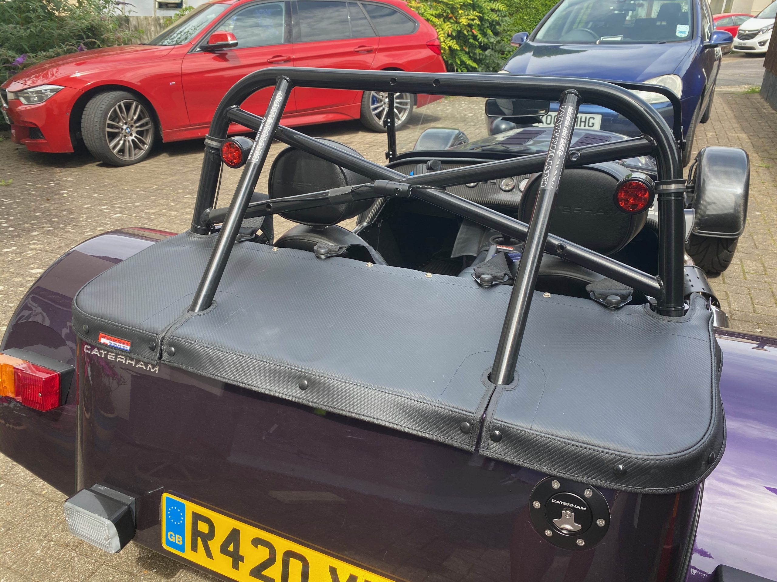
Anyway, that meant that the hood sticks I had installed on the car for the full wet weather hood were redundant and clattered around a bit over bumps.
And so removing the hood sticks cuts down on the clutter but means that the boot cover doesn’t fit correctly and is baggy on the top of the boot.
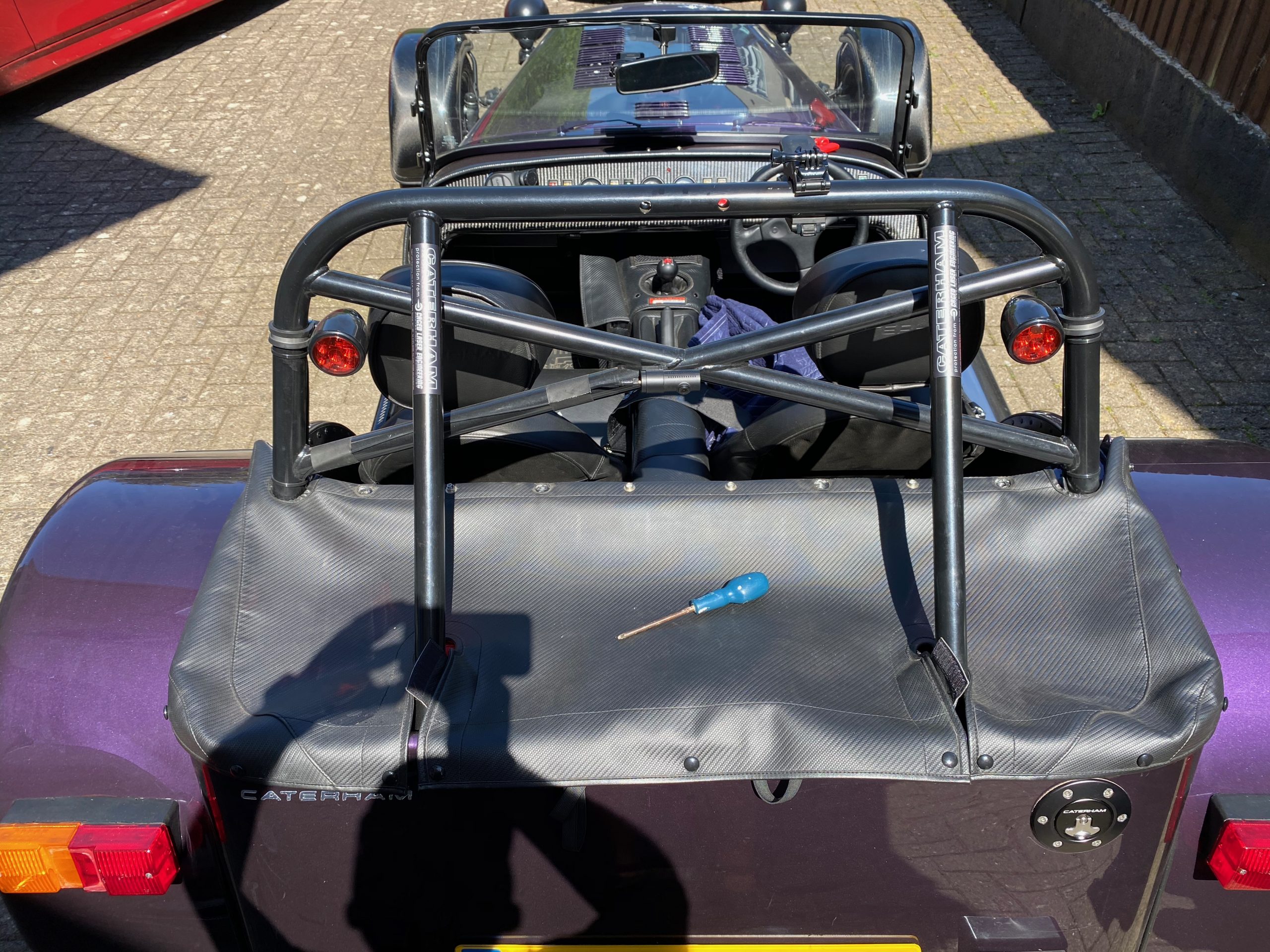
Here’s the old boot cover looking rather baggy:
Which leads us to Softbits for Sevens boot cover replacement (https://www.softbitsshop.co.uk/the-boot-cover-58-p.asp)
Now, I’d had the new boot cover for over a year and not got around to fitting it. The winter and then pandemic meant I’d not been out in the car very much. And if it’s stuck in the garage then its not so easy to manoeuvre around in there.
So, with the weather on my side for a couple of days I decided to have a go at the boot cover. Read on to find out what hacky-bodge of a tool I came up with to make the whole thing work for me.
The Theory
The theory goes… you have to:
- Remove the old boot cover
- Extract the aluminium stiffening bar from the old cover
- Cut a slot in the new cover to insert the old stiffening bar into
- Mark positions for holes along bulk-head edge of the new cover to match holes in the bulk-head
- Stamp out the holes you just marked that line up with bulk-head holes
- Fit new cover to bulk-head
- Punch a hole in the new cover for each stud
- Attach new stud
- Repeat steps 7 and 8 for each of the studs (it was 13 studs on my 2017 car)
In the Bag
When you order the boot cover from SBFS you get:
- The cover itself,
- 16 fixing studs (caps and buttons),
- A cutter for cutting holes in the hood fabric (for the studs to fit through) and
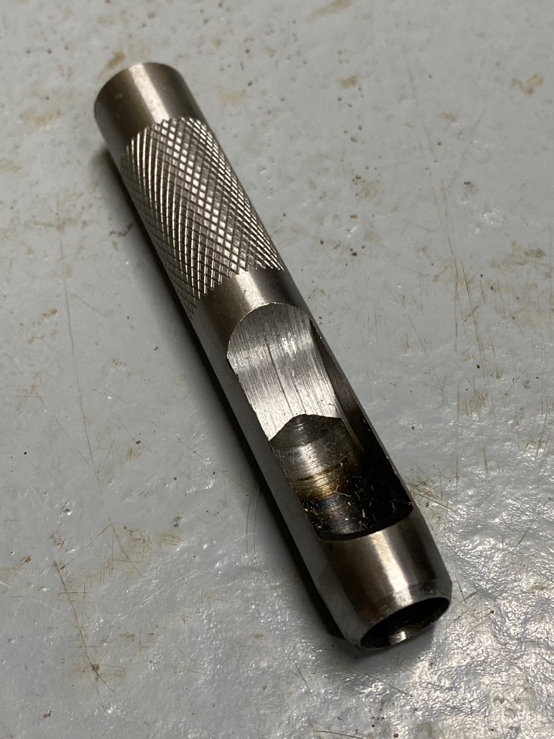
- A “doming” tool to mould the top of the deformable button shaft and so seal the button and cap together, with the hood fabric between them of course!
Here’s the diagram of the sandwich you have to make (updated from the SBFS website):
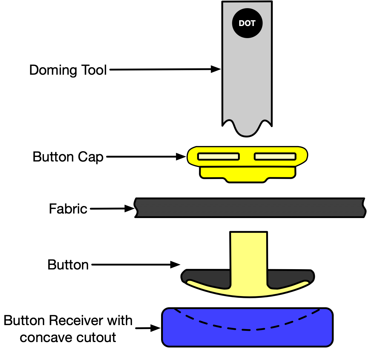
From the top of that diagram we have:
- Doming tool
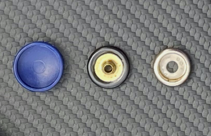
- Button cap
- Boot cover fabric
- Button
- Button Receiver (showing where the button goes with the dotted line)
The thing I’ve called the button-receiver is a blue concave dish which is used to give a stable base for the button to go into when you’re whacking it, something to stop the button being deformed/dented/dinged as you smash the crap out of it and to spread the load a bit too I guess.
Tricks of the Trade
Tristan from SBFS also gave me the following tips:
- Leave the new cover in the sun for an hour or so (if such an orb exists in your sky) to soften the material, make it more pliable and also so it will shrink slightly once fitted and cooled.
- Do the bulk-head first
- Then start with the centre rear stud and work outwards and towards the front.
- Also got this (paraphrased) from somewhere on the SBFS website: make sure there’s no slack in the press studs once fitted – the cap should not “rock” on the button shaft and be loose. The button and cap should squeeze the hood material and make a tight fixing.
With all that out of the way, here’s what I did:
Remove the Old Boot Cover
We have the 4-point harnesses on our car, so they need to be removed along with the four poppers that can be used to secure a tonneau, if you have one. The tonneau poppers have philips/posi heads and are easy to remove. The harnesses are less easy to remove, especially with the track-day roll-over-bar, there’s not much room to get the outer bolts out under the roll-over-bar. You obviously have to make sure the harness bolts are torqued up correctly when re-installing them – They’re the only thing keeping you and the car together if you ever have a significant deceleration event (or crump/off as we call it!).
Once those are removed the boot cover comes away from the car.
Extract the old Aluminium Stiffening Bar
There’s already a slit in the old cover that was used to insert the stiffening rod, so the stiffening bar slides straight out of what is a wide hem in the bulk-head (front) side of the cover. My stiffening bar was really banged up and I took some time to straighten it as much as I could before inserting it into the new hood.
Cut Slot in New Cover
The new boot cover didn’t come with any way of fitting the stiffening bar. So I put a slit in the off-side side of the new cover. Obviously the slit needs to be on the underneath of the cover. There was also an arrow marked on the stiffening bar, showing what direction it should be inserted into the boot cover hem.
At this point I also cut the length of the stiffening bar. The new cover was slightly narrower than the old cover and the stiffening bar would have been too long. I cut about 10mm off each end with some tin-snips – that may have been a little bit too much than I could have got away with, but I wanted a bit of slack at the ends of the hem so I wasn’t forcing the stiffening bar into the new cover hem.
Mark Bulk-head Hole Positions
You now need to transfer the position of the holes in the bulk-head onto the new cover, ready to cut holes for the harness bolts and tonneau poppers.
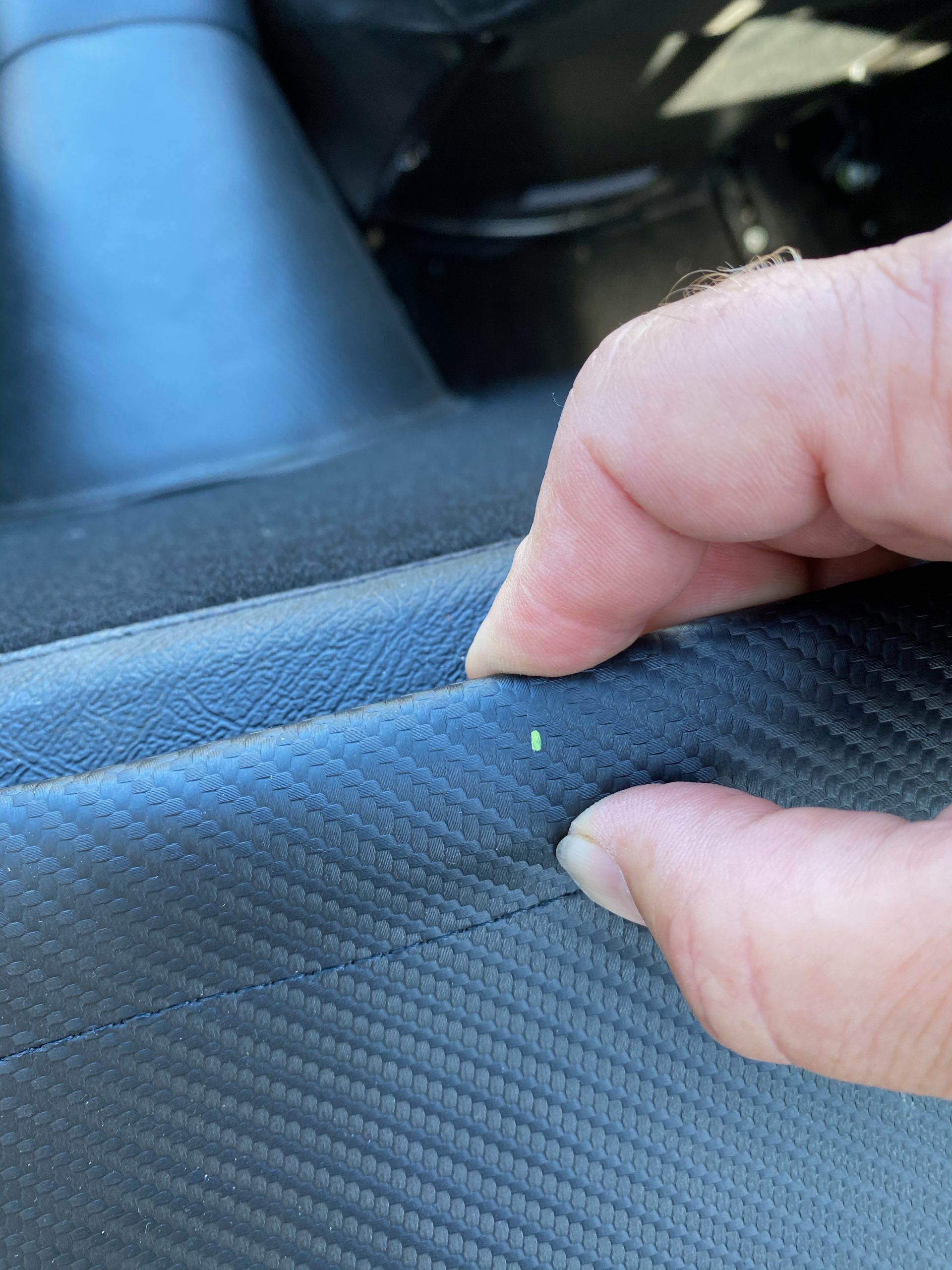
The way I did this was to lay the new cover over the bulk-head so it was central between the roll-over bar uprights. Then I marked the new cover, with a green paint marker pen, where the harness and popper holes were – being very careful to be mm accurate.
That gave me the lateral positions of where the holes should be.
I then measured (with the stiffening rod slotted into the boot cover) the centre line of the stiffening rod, which was 11mm from the edge of the cover. I could then measure 11mm from the edge of the boot cover to line up with each of the dots I’d marked laterally.
Cut Bulk-head Holes in New Cover
Before going any further, I offered the new cover up to the car bulk-head again… and again… and again… to check that I had everything marked out correctly and looking like I wasn’t going to have to buy a new cover after screwing things up! This was the point of no return.
Now I’ve got the positions where I need to cut holes where the bulk-head popper screws and the harness bolts will go.
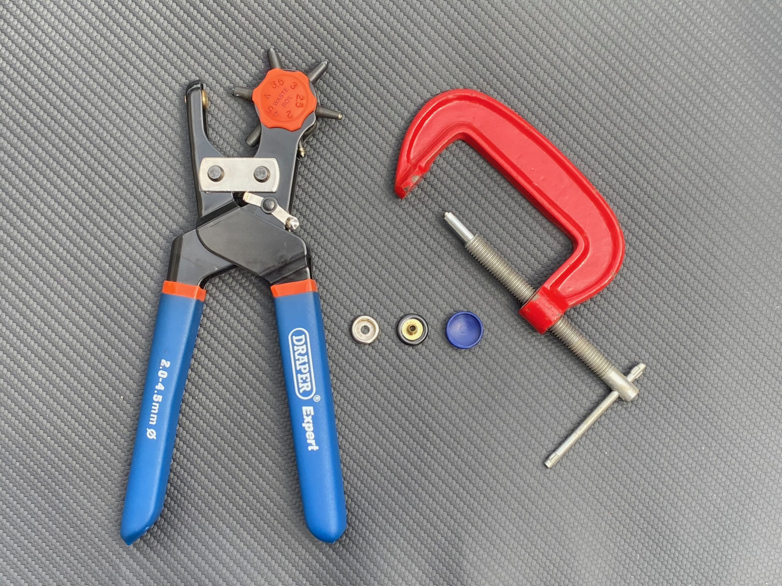
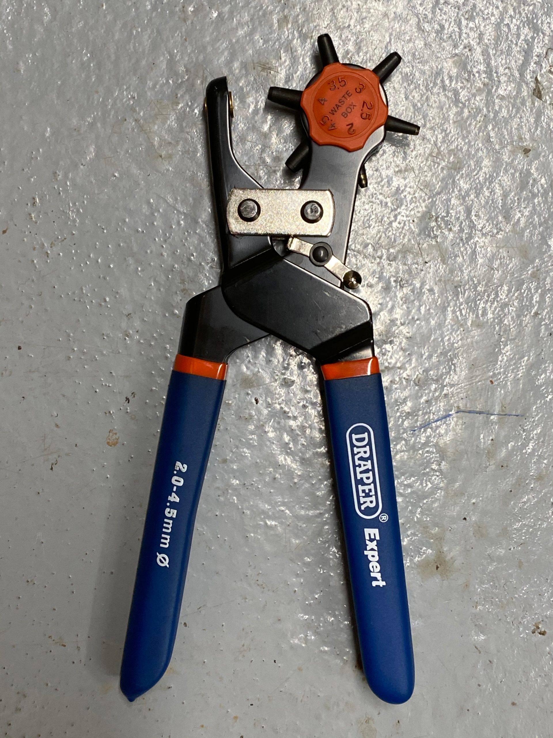
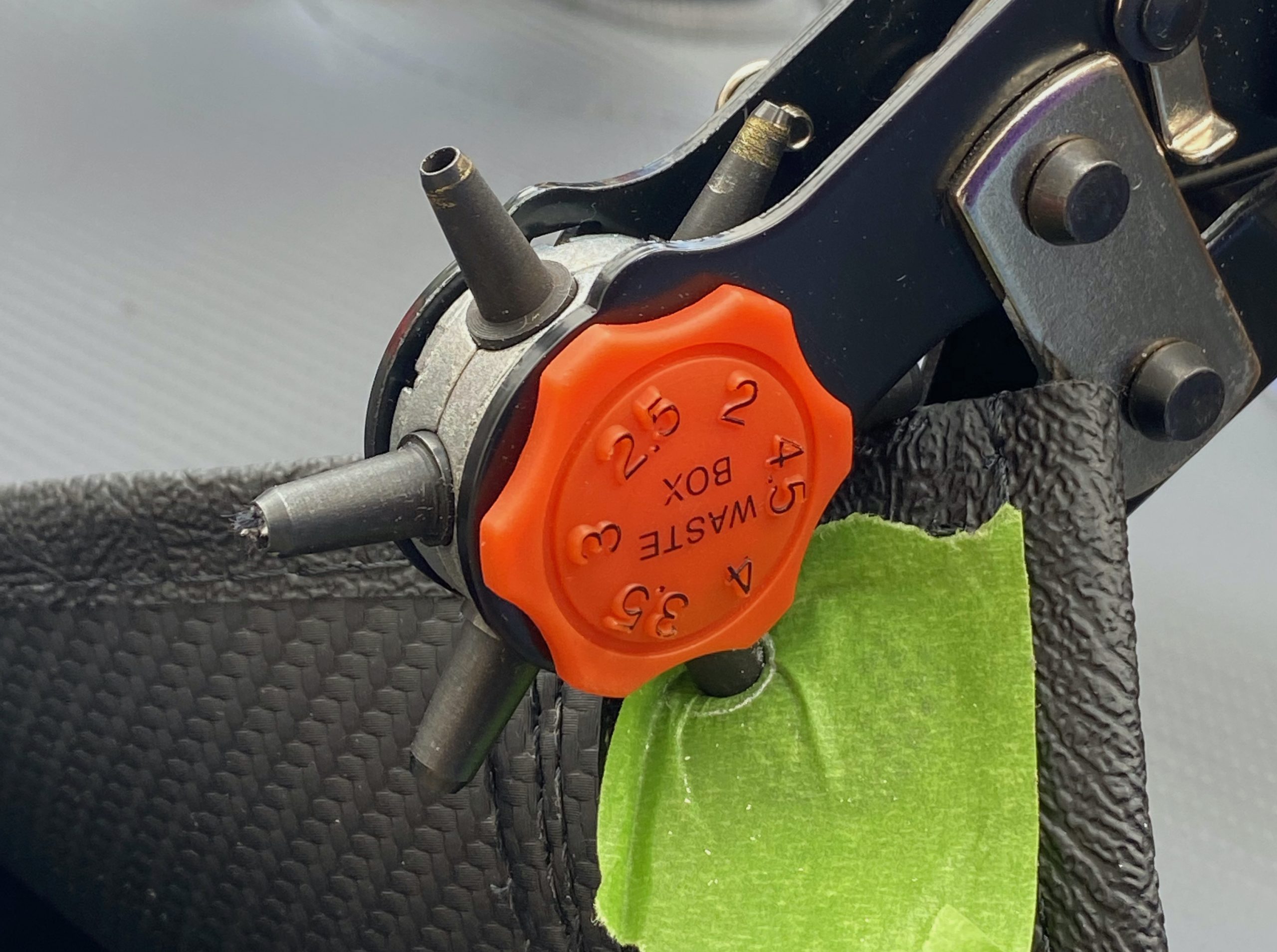
For the popper screws I used a 4mm punch on my leather punch. SBFS give you a cutting tool in the boot cover kit, but my leather punch was a much more precise tool to use. And it also solved the same sort of problem that the g-clamp hack solved for when attaching the press studs (see later in this post).
For the harness bolts I used at 12mm hole punch
Fit New Cover to Bulk-head
Now it was just a case of refitting the new cover by fixing the poppers and harnesses back into place.
Fitting the Studs
Now comes the tricky bit.
With the new boot cover attached to the bulk-head you have a flapping boot cover that now needs all the studs attaching.
However, the simple “doming” tool that comes with the boot cover kit, seems to be a little light weight for the job.
The idea is that:
- You put a button (that has a deformable shaft on it) through a hole you make in the cover fabric,
- A popper button-cap goes on the shaft of the button, sandwiching the boot cover fabric
- You put the blue button receiver on the back of the button and place it on something substantial to take a few knocks
- Line up the doming tool on the button shaft
- Whack the hell out of the doming tool to flatten the button shaft and stop the button cap from coming off again
All of that was a problem for me.
With the boot cover attached to the bulk-head there’s no easy way of finding anything substantial to place the blue button receiver on and then to do the whacking needed to dome the deformable button shaft.
One option would have been to mark up where all the 13 press studs needed to go, then take the boot cover back off the car (undoing the harnesses and poppers again). With the cover off the car I could use something solid behind the button receiver to put enough energy into the doming tool to make the domes (i.e a chuffing big lump hammer). But that didn’t sound like a good idea. It was a lengthy job to take the cover off, for sure, but I’m sure that as I stretched the hood applying the poppers in turn, the positioning of the next popper to be inserted would change… and lead to slack in the cover once all the poppers were done and then the cover refitted. The only sure way to do it with this taking-the-cover-off-again method would have been to take the cover off and on again between each stud – that would take forever and not be good for the longevity of the harness and popper fixings. So, I needed a different approach.
With the boot cover attached still, I tried putting some small “slabs” of marble I had lying around the garden onto the boot cover, under the button receiver. The slabs gave me something sturdy to hit against, but that was going to mark the cover and there was nowhere near enough “mass” in the slabs to allow enough reliable whacking.
SBFS do provide a tool service where you can pay a deposit and then £20 for the hire of a proper tool to fit the studs. But I hadn’t planned to do this job and so didn’t have time to arrange for the tool to be sent out and you can only have it for 7 days anyway. You also have to be a Lotus7.club member, which I am of course.
The proper tool you can hire looks like this, from SBFS website:
So… I pondered the problem over night.
I came up with a few hair brained schemes to try and squeeze a dome onto the button shaft but nothing really grabbed me as being totally fool proof ( or at least “this fool” proof!)
I thought of using adjustable pliers, mole-grips and even a tool I’d bought a long time ago that did plastic press studs (that showed promise but it wasn’t “person” (pronoun sensitive) enough for the job of the metal press studs needed for this project).
In the process of testing a few things out, I also managed to use up the three spare studs and caps I had over. I had 13 studs to fit, 16 came in the kit and I used 3 in my tests. I had no spares to get anything wrong now!
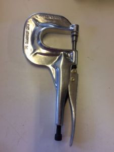
And then the brain wave hit me… I could hack a g-clamp!
The G-clamp Hack
I have a few g-clamps kicking around the garage, so I could sacrifice one for the cause.
My first idea was to use the g-clamp as it was.
But… the combination that needed to be compressed, to create a dome on the button shaft, was too unstable. It needed the button receiver, button, boot cover fabric, button cap and doming tool all the be compressed together in the g-clamp and it all just crumpled under any pressure.
I needed to stabilise the whole assembly.
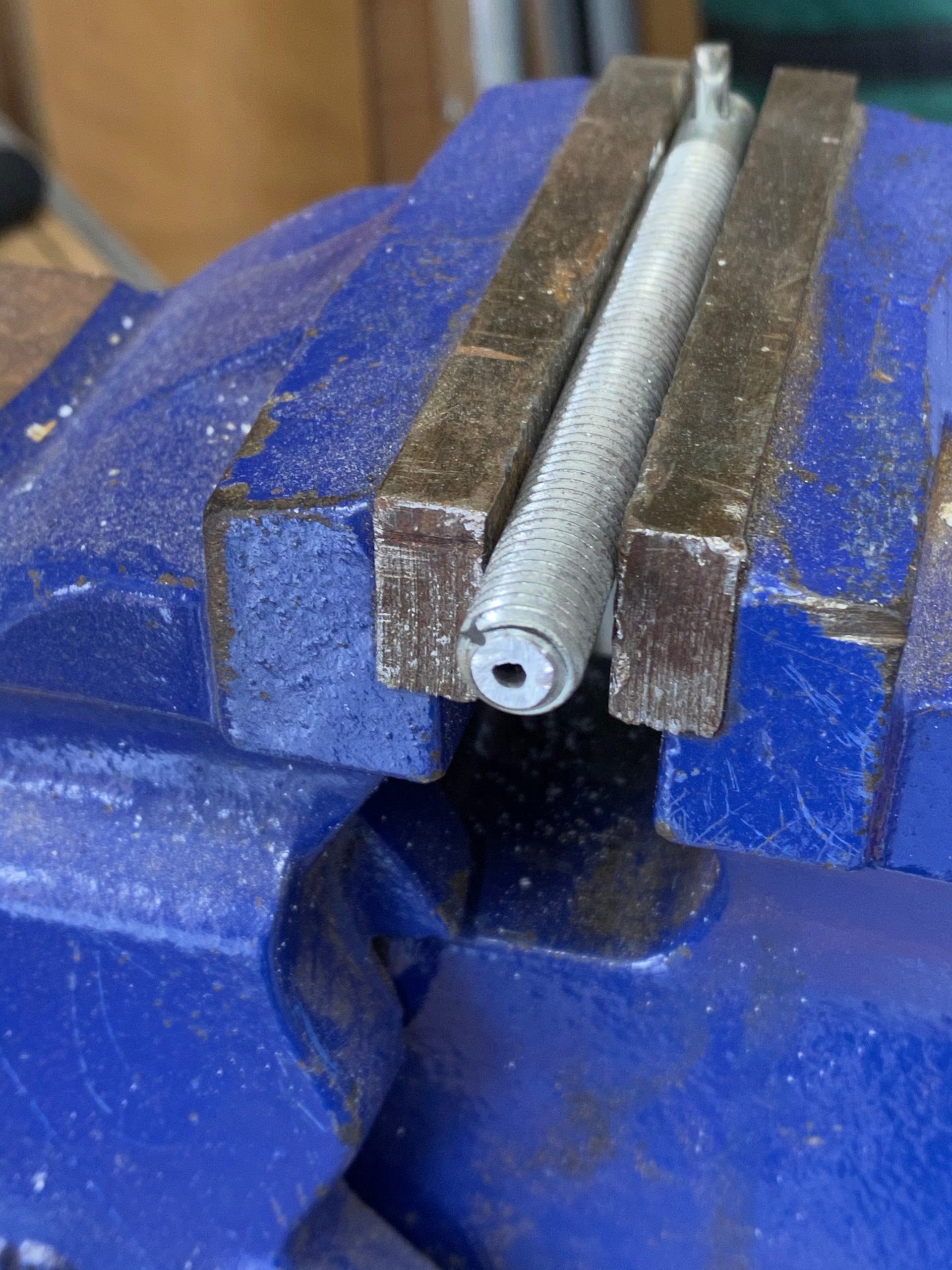
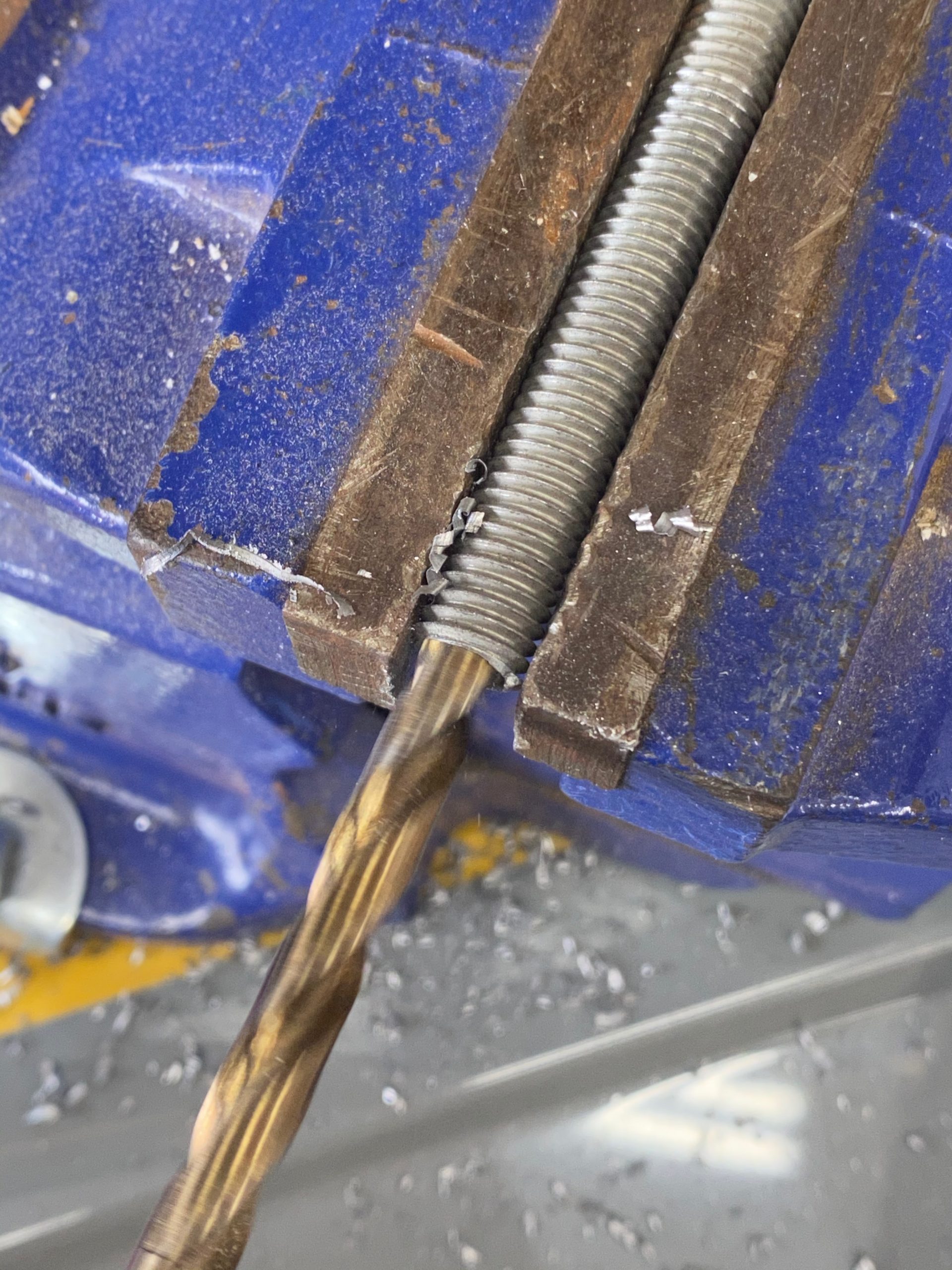
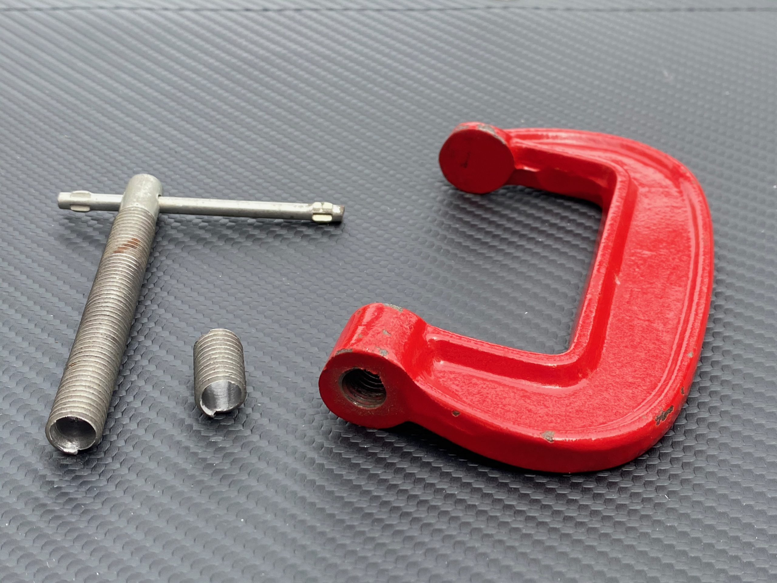
So, the next brain wave was to bore out the g-clamp threaded bar and insert the doming tool into it. That would keep the doming tool stable and apply pressure down though the shaft of the g-clamp thread and directly through the doming tool.
The g-clamp I selected was probably a little to small.
I didn’t want to waste one of my big g-clamps but I probably should have used a bigger one.
The problem was that I needed a 7mm bore in the g-clamp thread and that meant the remaining wall thickness around the bore I created was too thin. My g-clamp threaded shaft was 10mm diameter, leaving very little material after boring it out and taking into account the depth of the thread. More bored hole was showing through the bottom of the threads on one side!
Later on that bore wall would bend and eventually snapped after about 9 studs, meaning I had to re-bore the g-clamp threaded bar again. But that was ok… the g-clamp was sacrificed for the cause and as long as I could get all 13 studs completed then I was a happy camper.
The rest was pretty simple and would go like this:
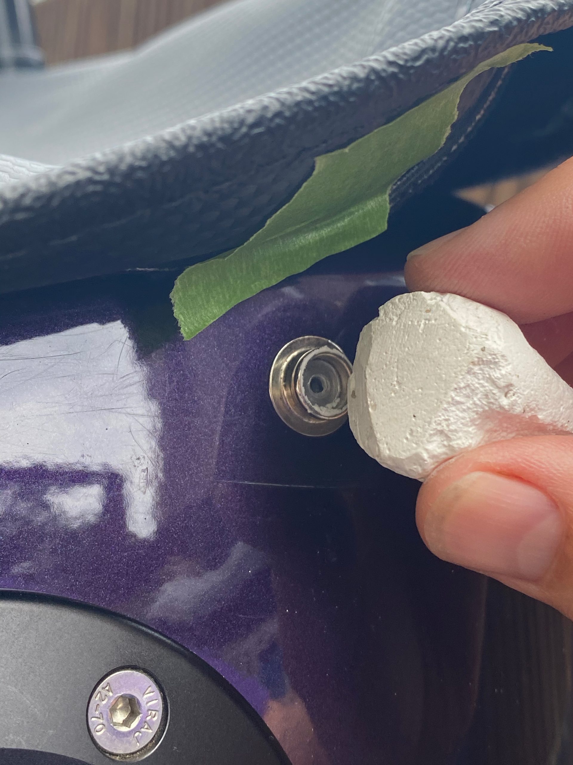
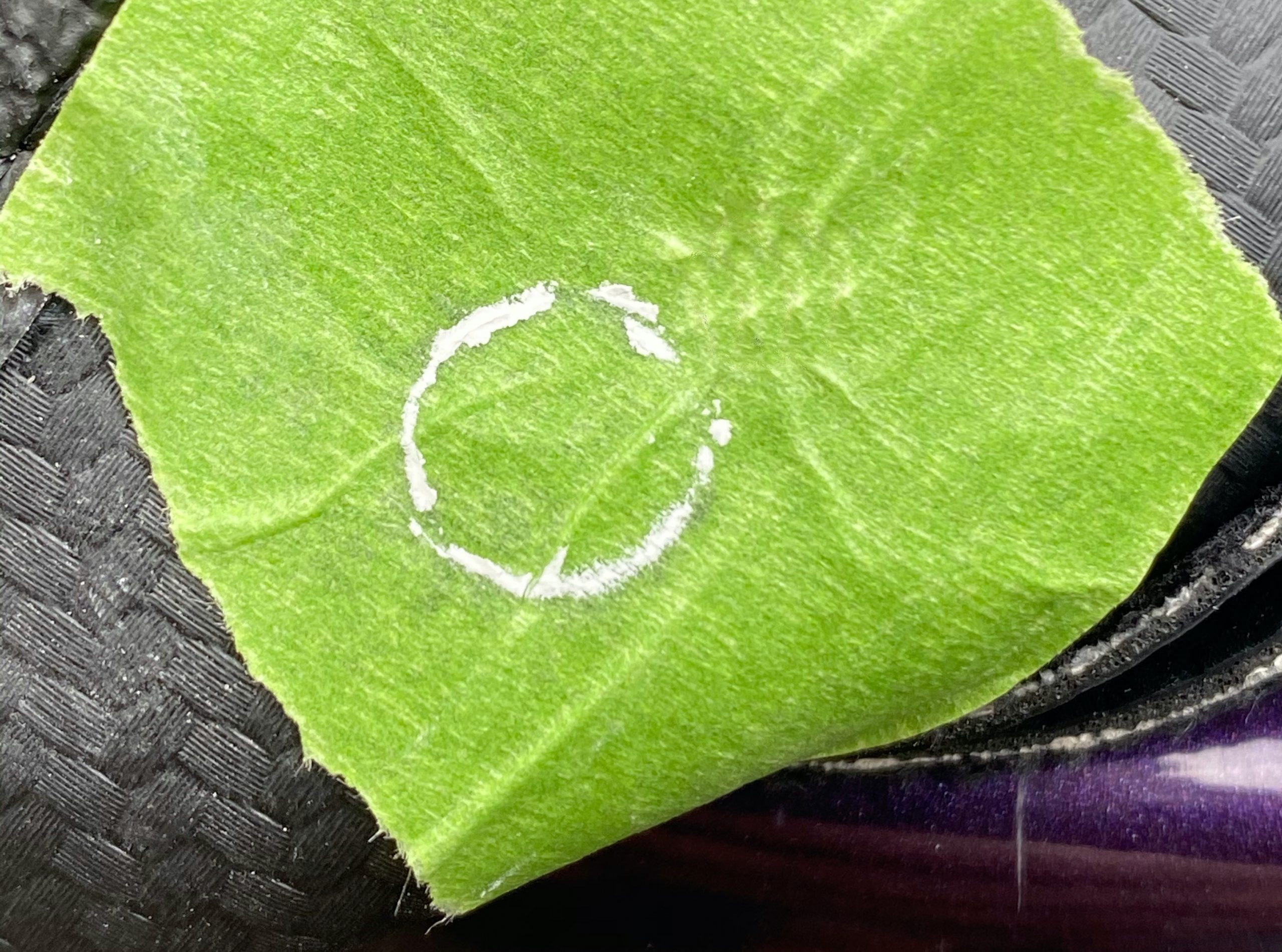
- Put some masking tape on the under side of the boot cover. I could probably have missed this out but it gave a good key for the chalk
- Apply chalk to the bodywork popper
- Pull the boot cover taught and press the masking tape against the chalked popper to leave a nice clear circle of chalk
- Punch a 4mm hole through the boot cover in the centre of the chalk mark
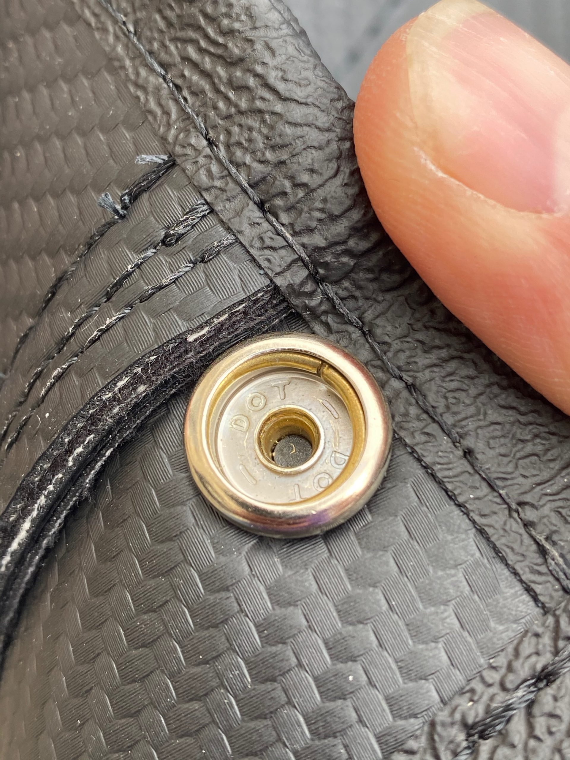
- Thread the button through the boot cover
- Apply button receiver, button and button-cap to the boot cover
- Clamp and squeeze the crap out all this press-stud, g-clamp, doming tool sandwich
Here’s some pictures of all of that…

Hopefully, the dome I made on each stud will stand the test of time. The fixing looks really secure to me, but only time will tell if its secure enough. There will be a note here from “future John” if they don’t survive.
What would I do differently?
- Use a bigger g-clamp so the threaded shaft doesn’t deform under load. Mine had a 10mm thread diameter. I’d go a couple of mm larger than that if possible
- Bore the g-clamp thread to a couple of mm less than the doming tool length. That should keep the whole stack more stable.
- If I was doing this a lot (and couldn’t get the proper tool) then I’d put a split pin through the g-clamp thread and the doming tool to stop the doming tool from falling out of the bore made in the g-clamp thread.
- I had a bit of slack between the centre-most popper and the one’s directly on either side. I should have made the centre popper more taught and then applied more lateral tension when installing the two poppers on each side of it.

Leave a Comment