

Drip, drip, drop, click, bugger!
… or in other words… rain… followed by another wiper fuse blowing.
The Story So Far:
For those of you that need a recap, I’d tested the wipers in December, prior to the IVA (Individual Vehicle Approval) test, and they had also been tested by the dealer that sold me the kit, Williams, at the Post Build Check. However, on the morning of the IVA, at 7:30AM, just as the heavens opened, and as I was pulling off our driveway, they stopped wiping and just sat still. I had to drive to the test centre, getting wet and knowing that with the wipers broken I was heading for a certain failure.
We did get them going again during the IVA but only with the help of a very considerate examiner and a spare fuse.

Since then the wiper fuse has blown a total of 4 times, not a big problem, mainly because I was intrigued as to what was going on and was increasing the fuse size as each new fuse blew. A couple of the times it blew was when I was testing, but it also blew a couple of times when it mattered and I had to drive in the rain with no wipers. But fortunately, I had decided to carry spare fuses after my school-boy-error of not taking any to the IVA test.
Well, of course, the standard response to any fuse failure is to adopt the age old course of action: throw in a bigger fuse and see what happens!
As the fuses kept blowing I’d managed to “do in” two 10As (factory fitted), two 15As and then finally found that a 20A held. I was still rather in the dark as to what was actually going on though. Was there a current spike that was “just about” holding with a 20A? Or was it more of a sustained current draw that was within the limits of this 20A… and of course, why do I need a fuse that’s double the factory fit item?
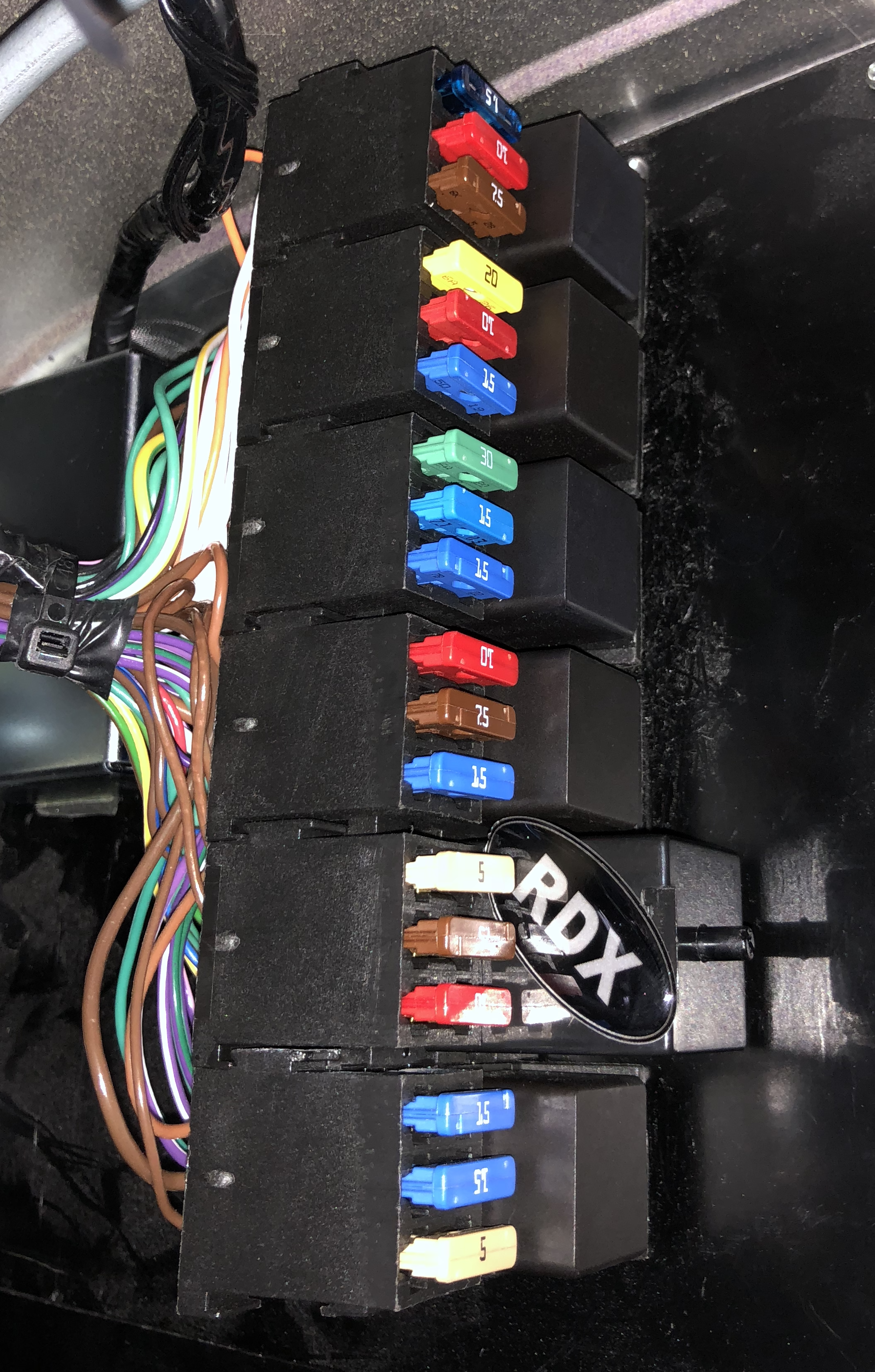
[ Note: the image above has an RDX relay where the standard indicator relay should be – that’s another story but relates to new LED indicators, brake, reversing and fog lights… but that’s another story ]
Now, sticking in a 20A is not quite the bodge-it-and-scarper approach that it would be to use a piece of tin-foil across the fuse terminals… as had been suggested by some, but it was close.
I went through a bunch of possible options that might be causing the problem. Clearly there was too much current being drawn as the wiper motor started. But I couldn’t imagine Caterham fitting a 10A fuse when they knew there was a startup problem with the motor… or could they? Of course this could be a defective motor, or there was some inrush current protection missing from my car.
Other options I thought of mainly revolved around the mechanical linkages getting “bound” and causing a higher than normal stall current in the motor. If that were happening then it would probably happen at some point no matter how long the wipers had been running… i.e. it could bind at a particular point in the cycle but it could take a few cycles before the problem showed itself.
That didn’t seem to be what was happening…. the fuses seemed to all blow when the wipers were first switched on… and more than that, at the very point the wiper switch was flipped. It did catch me out once when I thought that wasn’t the case, but in the end I decided that I had gone from slow-wipe to fast-wipe and the wipers had stopped mementarily in between those modes – so inducing a “start condition”. It seemed to me that if it was a mechanical bind then at some point in the wiper motion there would be a sticky point and the current would increase there. But it doesn’t feel like that’s what’s going on.
Ok, so it’s probably something to do with startup current. But how am I going to see exactly what’s going on. Hmm. A volt-meter or ammeter isn’t going to be able to tell the story at the split second when the wipers start up. I could use an oscilloscope but the only one’s I’ve got are 15+ years old and are not the sleek slim LCD units you can buy these days. I’ve also got some similarly old logic-analyzers that I could have broken out, but they too are bulky and difficult to extract data from to include in this blog. Very Web 1.0.
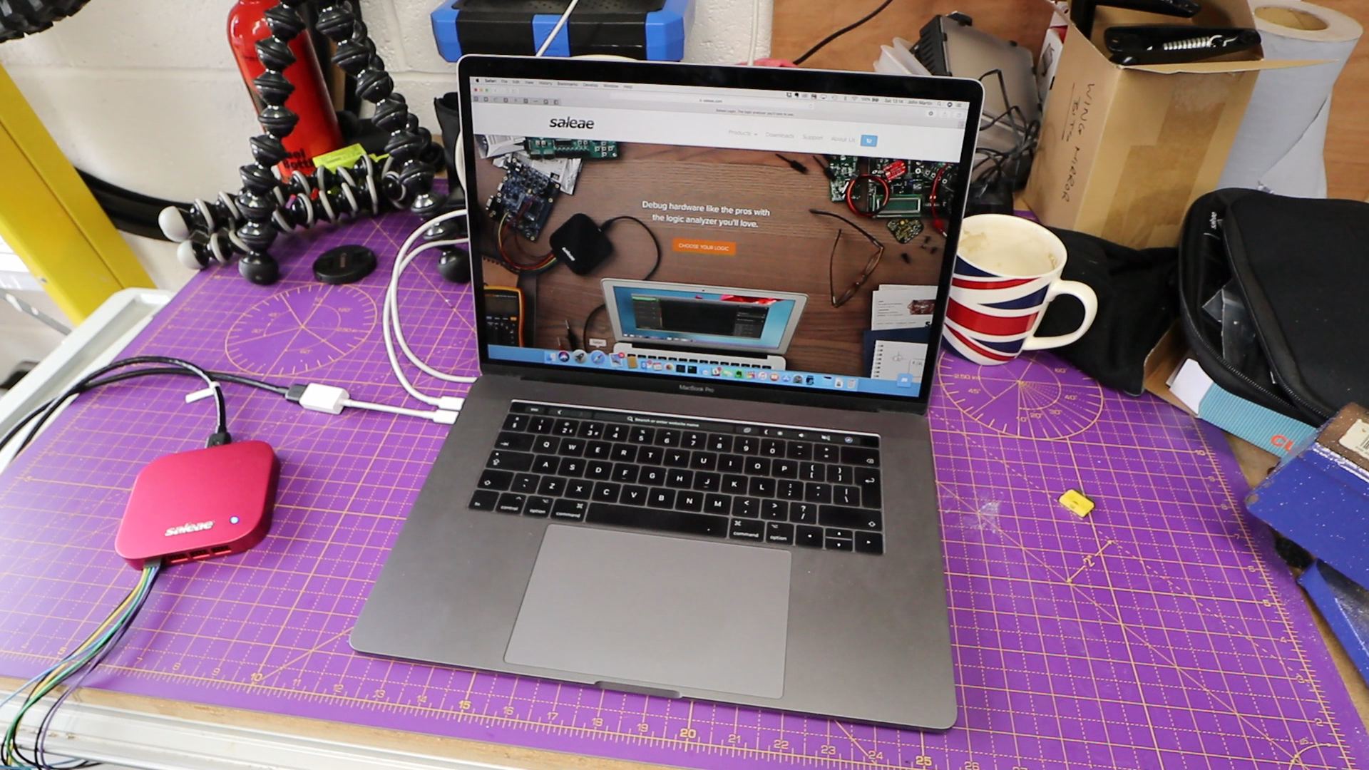
Bring on the Salaea Logic Pro 16. My modern way of doing oscilloscope and logic analyser work is to use the logic/analogue PC dongle from Saleae. They come in different sizes, i.e. inputs, speed and colors. I have the 16 channel Pro version in a fetching anodized red.

Salaea can be found at www.saleae.com.
The Salaea 16 Pro is an great bit of kit. It plugs into a USB socket on your PC and can deliver up to 500Ms/s (mega-samples per second) logic acquisition and 50Ms/s analogue acquisition all from a box that fits in the palm of your hand. Each of the 16 channels can be set to logic or analogue acquisition and the whole thing also takes its power from the USB bus, so only needs a single cable. I only need a single analogue input for this investigation, but nice to have 15 backups!
I think for the higher acquisition rates you need to have a USB 3 port on your computer but for what I needed in this project, USB 2 was going to be fine. It’s also really tiny so hooking it up to a laptop meant that if I wanted to I could “go mobile” and connect up the rig to the car as I drove around. In the end I didn’t need that, but it was always an option.
On the PC side of things… I’m a Mac sort of person, so I had the Salaea hooked up to a Mac Book Pro. That’s way overkill for what I needed but if I wanted to “go mobile” I would have broken out an old MacBook Air or something.
Salaea are beta’ing (as I write this in April 2018) a live capture mode too… the current release of software only lets you see results once a capture has run. Again, that’s fine for this project but I’m looking forward to finding other projects where I can use that feature.
That’s the tool sorted, now how do I connect it to the car.
Hmmm… So… I’m looking to get current measurements of the wash-wipe circuit. I either need to put an ammeter type device in series with the circuit or I need a current probe. I don’t have anything I can connect to the Saleae that is like an ammeter or that I could construct… to do that I would need an accurate and low resistance that’s in series with the motor and that I could then measure the voltage drop across. We’re talking about 10 or more amps here so the resistance would have to be very low – or else I’m going to be affecting the measurements by adding more power draw and voltage drop. I didn’t have those sort of components to hand.
My solution was a current probe. I have a 0-20/0-60Amp dual range current probe that generates a 10mV/Amp and 100mV/Amp in it’s two ranges. For a load of less than 20A (my 20A fuse is holding, so I’m interested in less than 20A draw) the lower current range of 100mV per amp should do nicely.
For those not familiar with current probes, they measure the net current flowing through any wires passing through their jaws. The effect is an electromagnetic effect that we won’t go into here. However, the result is that the net current flow produces a proportional voltage response on the probe’s output.
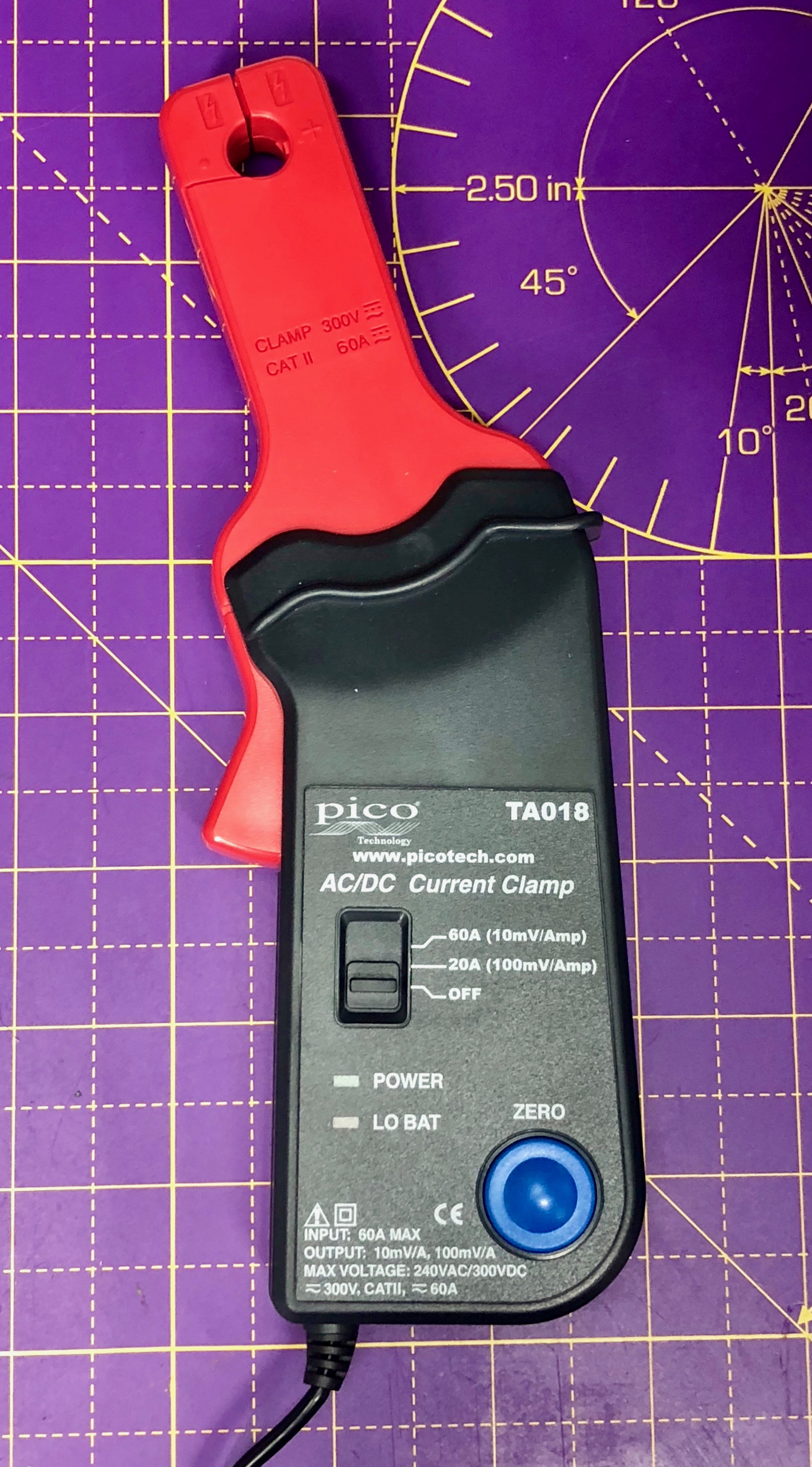
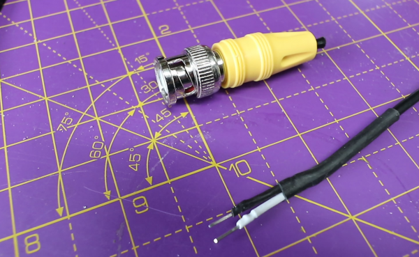
My next problem was that the current probe has a BNC connector on the end. That’s fine for the old-school oscilloscopes but not what the Saleae needs. It uses 1/10” headers for its input and has breakout leads that can hook up to 1/10” headers or at a push bare wires. I was unlikely to need the BNC connection type again, so… off with its head!
I could have made a BNC to 1/10” converter cable, but I was feeling lazy. That being said I also couldn’t just hack off the ends, I did need to at least provide something a little more professional – OCD, moi?!
Back on the Saleae side of things, it’s analogue inputs are configurable up to a maximum input voltage of 3.3v. So, with 20A and 100mV/A, I need a voltage range of 0-2V – that’s perfect for the Saleae. Bostin!
Now I need to figure out how to get the current probe clamped around the wiper circuit input. Hmmm (again)…
I dangled myself into the passenger side footwell hoping that the wiper motor wires were accessible – they weren’t. The wiper motor is tucked up under the passenger knee panel. Hmm. I could of taken the knee panel off but I was feeling lazy, as discussed above.
What about getting the probe on the back of the fuse panel. That had been the plan all along. But there wasn’t a lot of room there either. I’d probably have to unbolt the fuse panel to be able to get at it. Hmm.
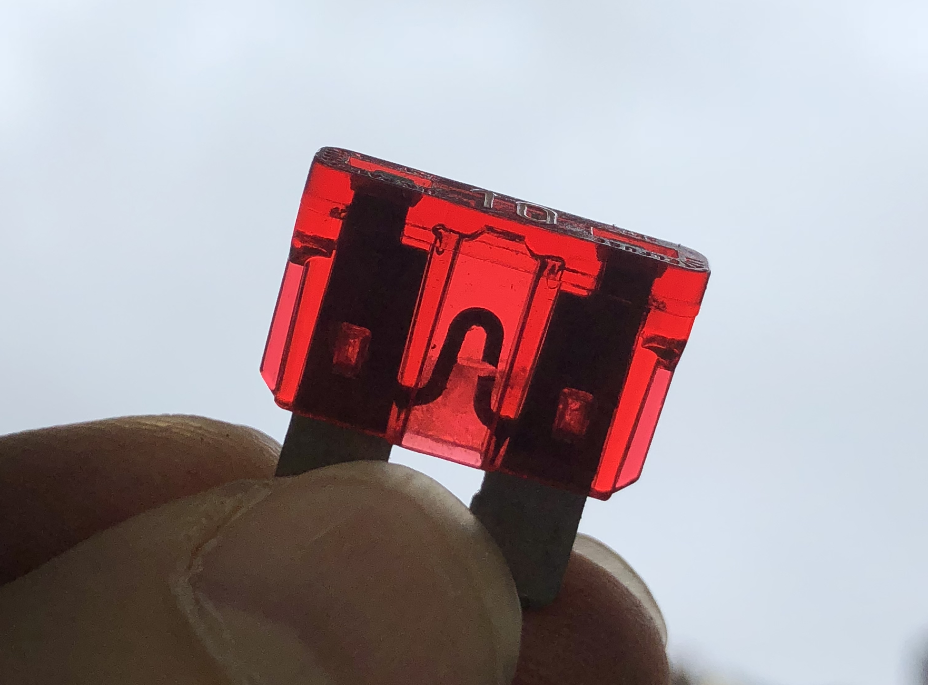
Then came a eureka moment. I’m sure this is something that old hands know all about and use all the time. But I was pleased I worked it out myself… Use… a… modified… fuse (as pictured above).
You’re regular automotive fuse is essentially a plastic molded holder for the fuse wire. My plan was that I could nibble away at the end plastic of a blown fuse and insert a wire loop that I could get the probe onto. It has to be a “blown” fuse or else my wire loop will only be in parallel with the fuse wire and I won’t “see” the full current in my probe. Then, once I have this fuse Frankenstein, I can pop it into the fuse socket for the wipers and attach my probe.
Here’s the modified fuse…
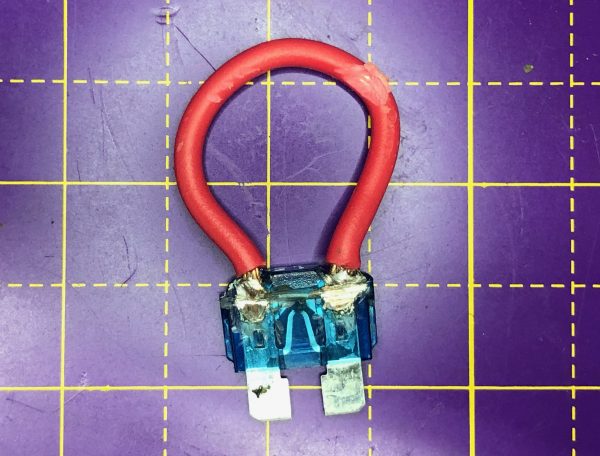
I could probably do a neater job than this second time around if I had another go – but it will do. I had to file away some of my soldered connections so the fuse would fit back into its holder and the wire loop got caught on the soldering iron at one point and so I lost a bit of the insulation – it’ll do!
And I also probably would have got the measurement done faster if I’d have taken the knee panel off… but lazy doesn’t mean lazy in all respects. When there’s a Eureka plan to hatch then lazy goes out of the window!
And here it is in the car with the probe attached.
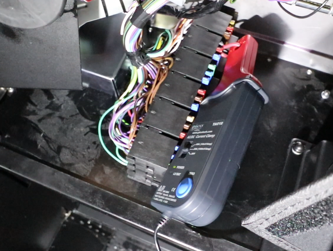
Now to take some measurements.
After a false start where I actually started to probe the wrong fuse, I finally found the right fuse (it’s tight up in that fuse box), and got to taking some measurements. I set the analyzer to 5ks/s and the full 3v3 input range. I didn’t need a lot of either time or voltage resolution… I was sure that anything that was going on was happening at the ms (millisecond) scale and not at the nanosecond scale. I was mostly right.
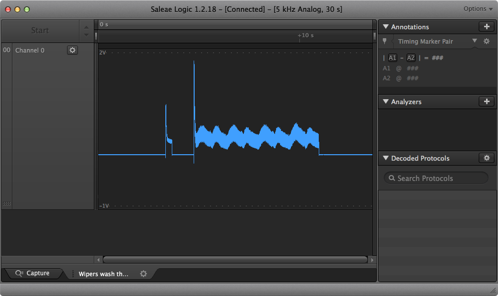
The image above is a screen shot from the Saleae with the probe being connected into the wider fuse socket. The first spike is the ignition being turned on. Then we see a big spike where the wipers are turned on. There are then 8 “bumps” showing the wipers making 8 sweeps (4 cycles of left then right). It’s not totally obvious to me why there’s a spike associated with the ignition switch being activated – though I assume its something to do with the wiper reverse/park, there’s a momentary energising of the motor as the park circuit decides that the wipers are in deed parked.
But we’re interested in the big spike…
We can see that the initial in-rush spike is large but also drops very quickly only to be followed by a wider almost the same amplitude second wave of current.
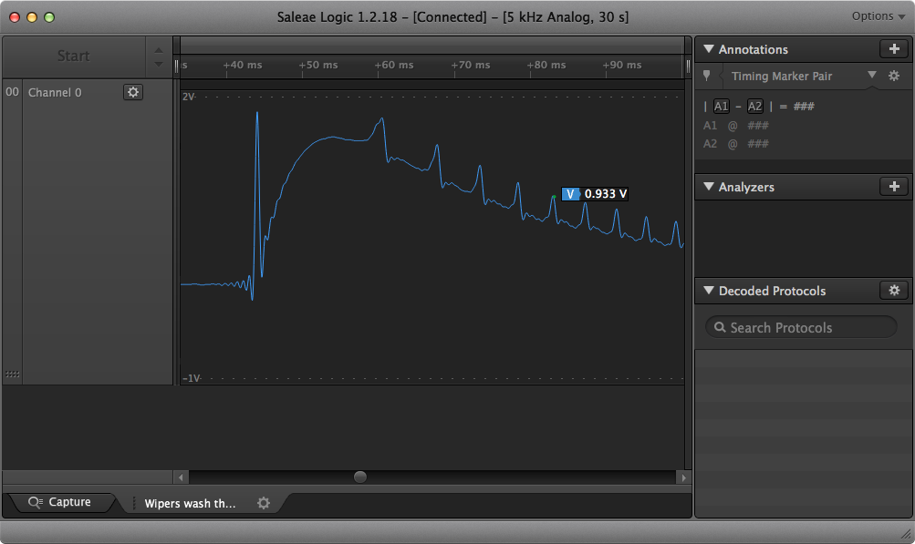
If we zoom in on the initial spike we can get a current reading…
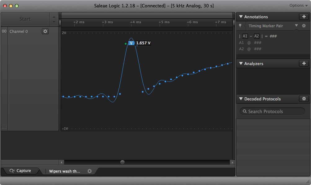
The 1.657V shown on the image indicates 1.657 X 10A (100mA/V), or 16.5A.
Ok. Problem identified. The motor is drawing some 17A for about 0.6ms then almost the same for a much longer period. The shape of the curve is a little odd, there’s clearly a decay going on here followed by a cut-off, so I suspect the current peak is a lot higher than what I captured. This is firmly in line with the stall current theory, the magnetic fields build quickly and the current would be infinite if it wasn’t for the resistance of the windings. But in a real motor the currents aren’t infinite – luckily. Phew… my 3 years of university motor and electro-mag theory are paying off! Time to dissect the time… and up the sample rate a bit.
So, we’ve got a current spike when the wiper motor starts. That’s normal. And at the time scale that a wire fuse is going to be worried about (millisecond duration) the current draw is around 17A. The question is still: why is it so high?
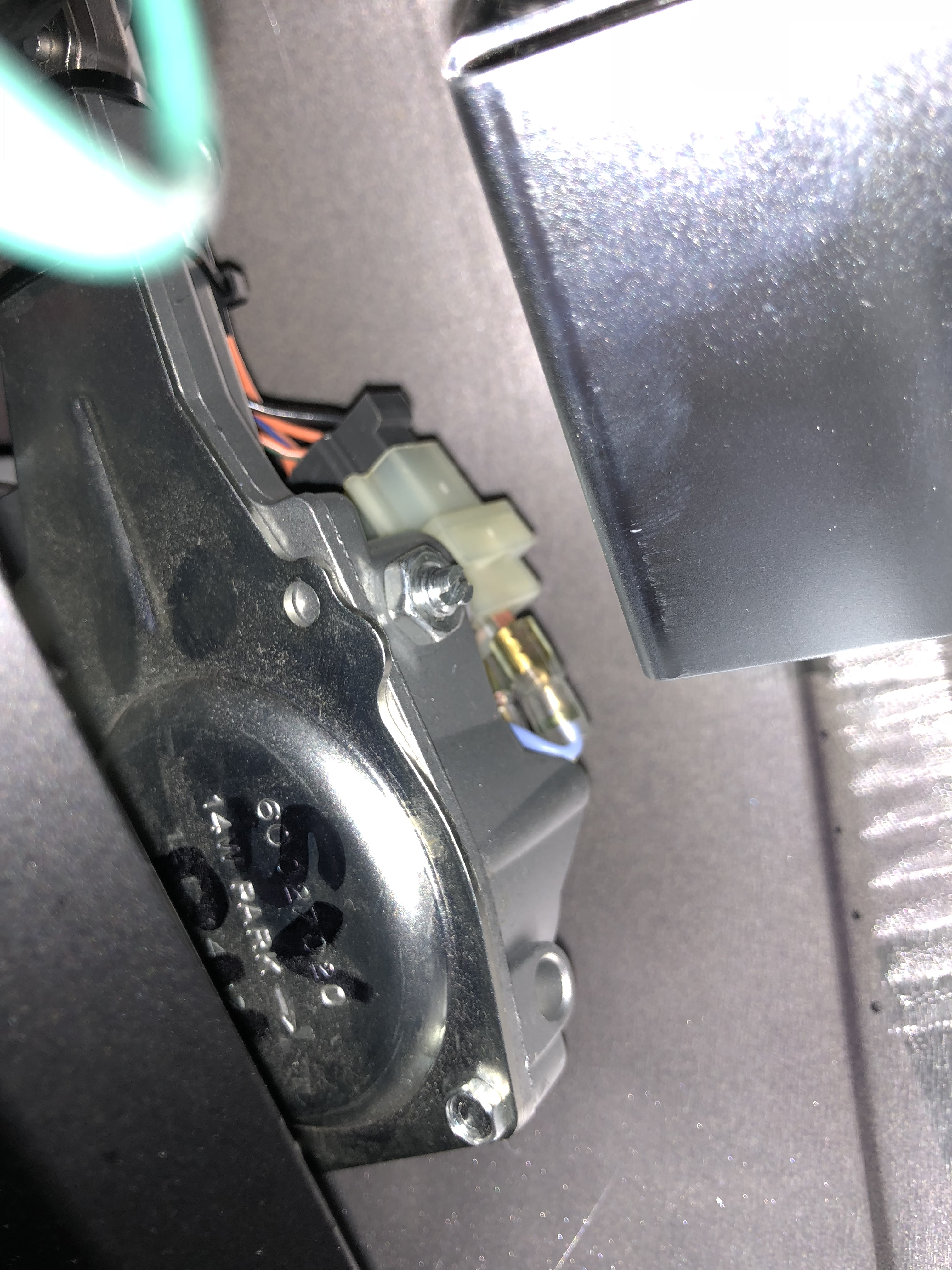
There’s some writing on the side of the motor that shows what looks like a “14W”. I’m not sure if that’s relevant but I’m clearly going to need to do some more investigating. Especially if the motor is 14W… the 17A startup current and the ~7A running current are way bigger than 14W. For those interested, 17A x 12V = 204W. You can do the other calculation if you like, consider it homework. That wold be 1/3 of a horsepower at stall… while that’s feasible, that’s not going to be needed to drive two small wiper arms I don’t think.
One of the causes of the large spike, could be that the motor is faulty or at least the windings are at the low resistance side of a manufacturing tolerance. I’m certainly not going to be taking the motor apart to dissect it, but I might put a ohmmeter across the terminals if I take it out.
Perhaps I still also need to look at the mechanical side of things. The wiper assembly shows the motor attached to a gearbox and then through a bar to two worm gears that drive the blades themselves. Maybe the gearbox is dry or the worm gears need lubricating. It should be simple to get some lubricant on the worm gears but getting the motor and gearbox out will have to wait for another day.
The only other option I can think of at the moment is that there should be some sort of shunt across the motor to dampen any inrush – perhaps that’s faulty, missing or not designed for.
Next steps are to see if this is a common problem that I hadn’t been able to Google on Blatchat… and to do some digging to see if there are any clues on the Caterham supplied wiring diagrams (though I’m less than confident that they reflect how my car is actually put together).
So, what’s going on?
Well, I guess I still don’t know. Though I know more detail on what’s going on at the current level.
And of course leaving the 20A fuse in place isn’t really a great option. The fuse is there, obviously, to protect against over-current. And with the stall current being below the fuse rating I have in there now, then a stalled motor isn’t now going to blow a fuse. I guess if the motor does truly stall then it’s going to get rally hot too… that’ll reduce the resistance of the windings enough perhaps to increase the stall current and blow even the 20A fuse. But that’s perhaps just wishful thinking… there’s a lot of metal in a wiper motor and it will take a long time to heat up and even then I doubt the winding resistance will fall low enough to blow the fuse. If I had a spare wiper motor I’d probably try that out – sounds like an interesting experiment.
More to come…
PS: This post was written in April of 2018 but for various reasons has only been posted now (June 2018). In the intervening time I’ve not had a chance to look any further at the Wiper Motor problem but my 20A fuse has held. Hopefully I’ll get a chance to look some more at this at a later date and report back.

Leave a Comment