
Day 4 of The Big Push – Phew! This is getting tiring! I’m glad I decided I needed to take some time off to get this knocked out. While I’m not getting as much time on the car as I hoped, I am making progress. All that’s going to change today… no distractions, no excuses!
Front Wings Again
Today, I wanted to at least get to the point where I had the Carbon Fibre Wings “tacked” onto the Wing Stays.
As far as I know the only hard and fast regulations around the front wings are the IVA trim needed around the edges of the wings (done) and the requirement that the leading edge of the wing has to be forward of a line drawn vertically at the front edge of the wheel (not tyre).
On this second point I have read blogs, and seen emails from Caterham, where they recommend the leading edge of the wing is 75 mm from the wing stay. That’s a good starting point but seems a little vague to me. It’s fine in the factory where they know what has been done to the car already but in a home-garage, where I’ve been tweaking and bending the wing stays, I could have inadvertently moved the wing stays fore or aft. In the correspondence I’ve seen it’s also not obvious whether that recommended measurement is to the front of the wing stay or the centre line. It’s much easier to measure to the outside front of the wing stay, so I assume that’s what they’re referring to. So, anyway, my recommendation is still to set up a plumb line of some sorts and verify that the wing will sit forwards of the wheel.
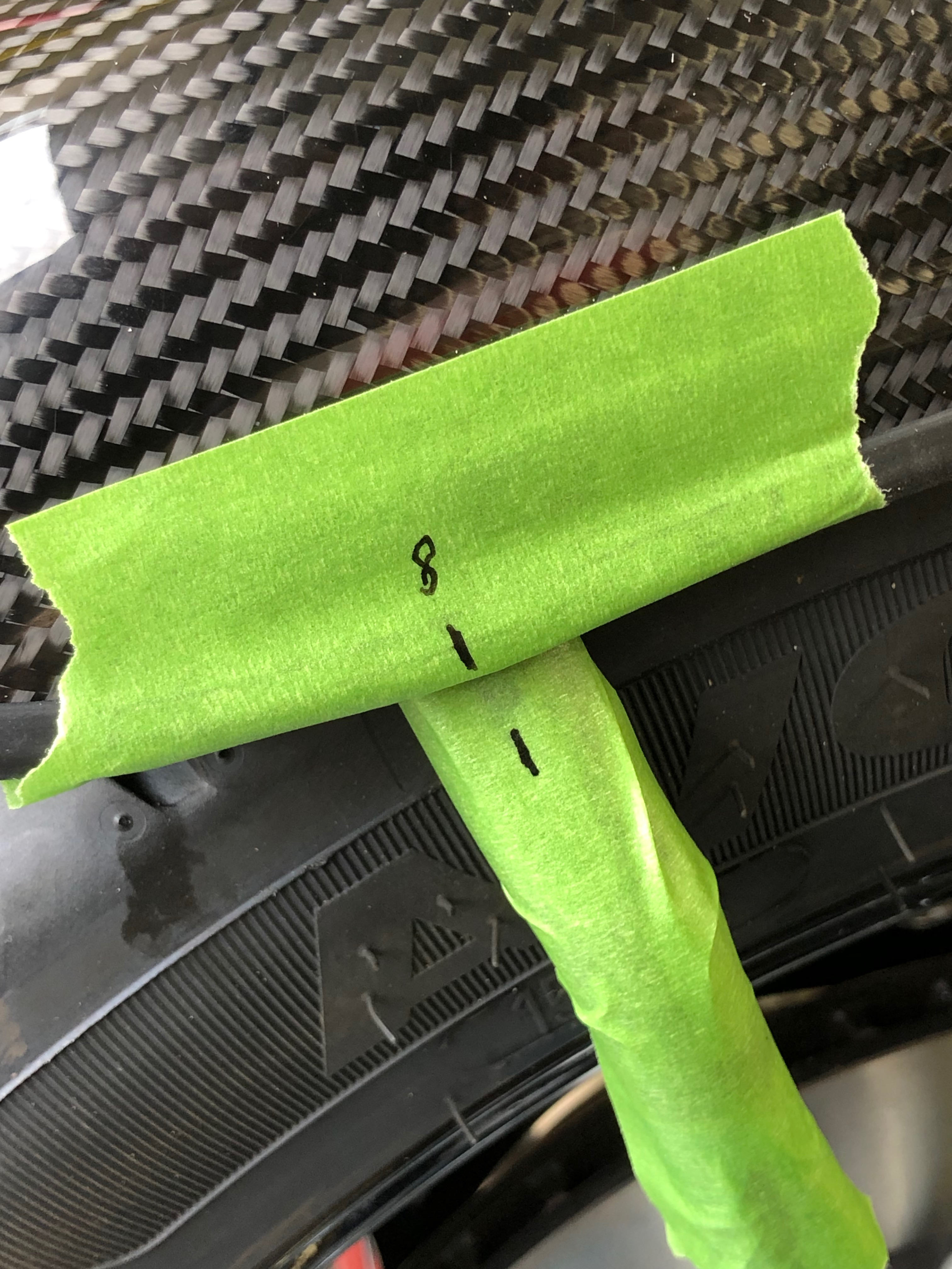
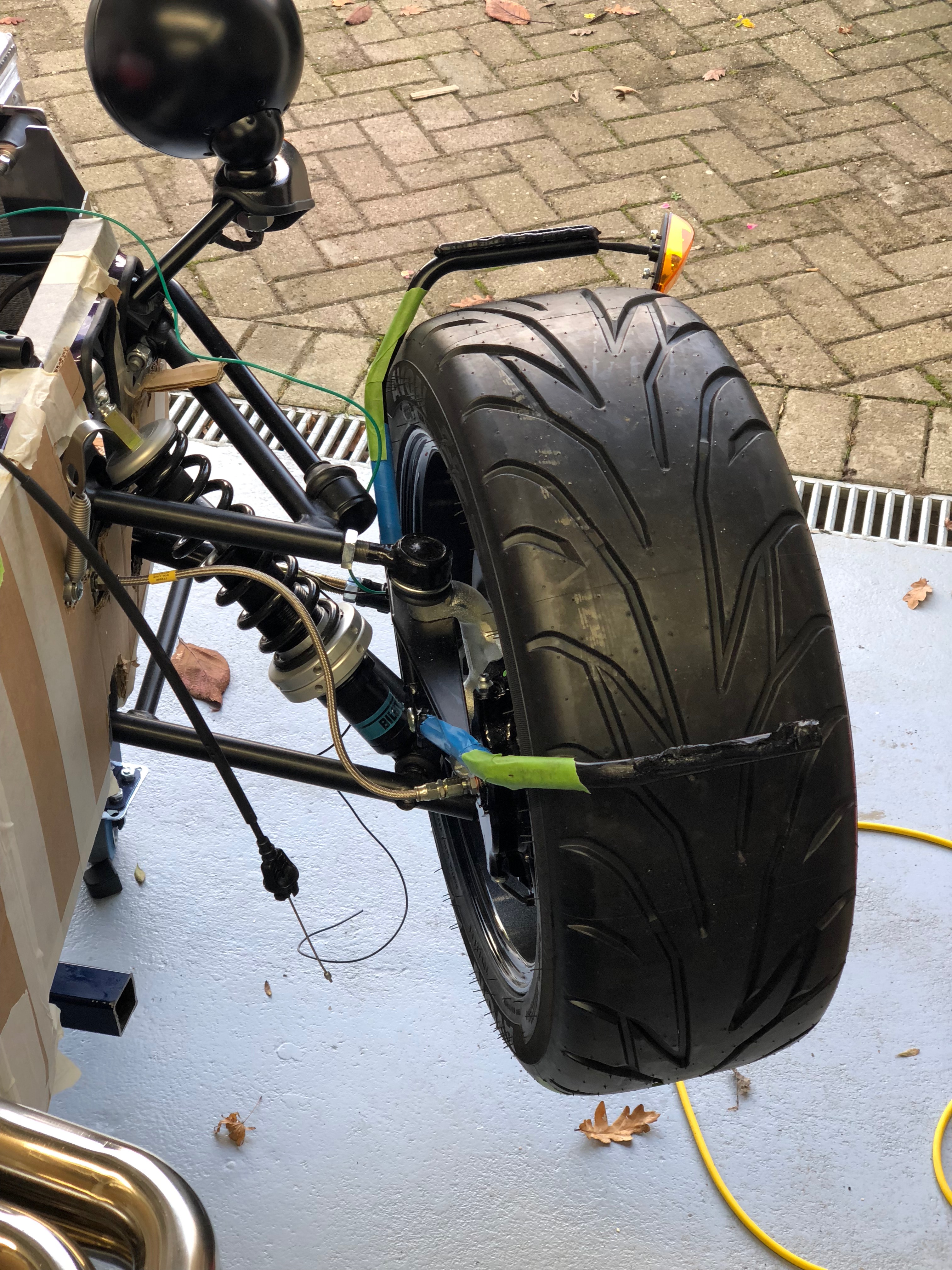
To this end, I sat a wing onto a wing stay and used a large set-square I had kicking around to make sure the wing was in front of the leading edge of the wheel. I then measured from the front of the wing stay to the front of the wing (including IVA trim). ISTM that a little extra distance would satisfy my fear of getting this wrong, so I set my measure at 80mm (8cm) and marked it with masking tape…
Next up was to try out the routing of the repeater wiring. I’d extended the earth lead of each repeater a couple of days previously so could try fitting them.
My repeater/wing install consisted of the following:
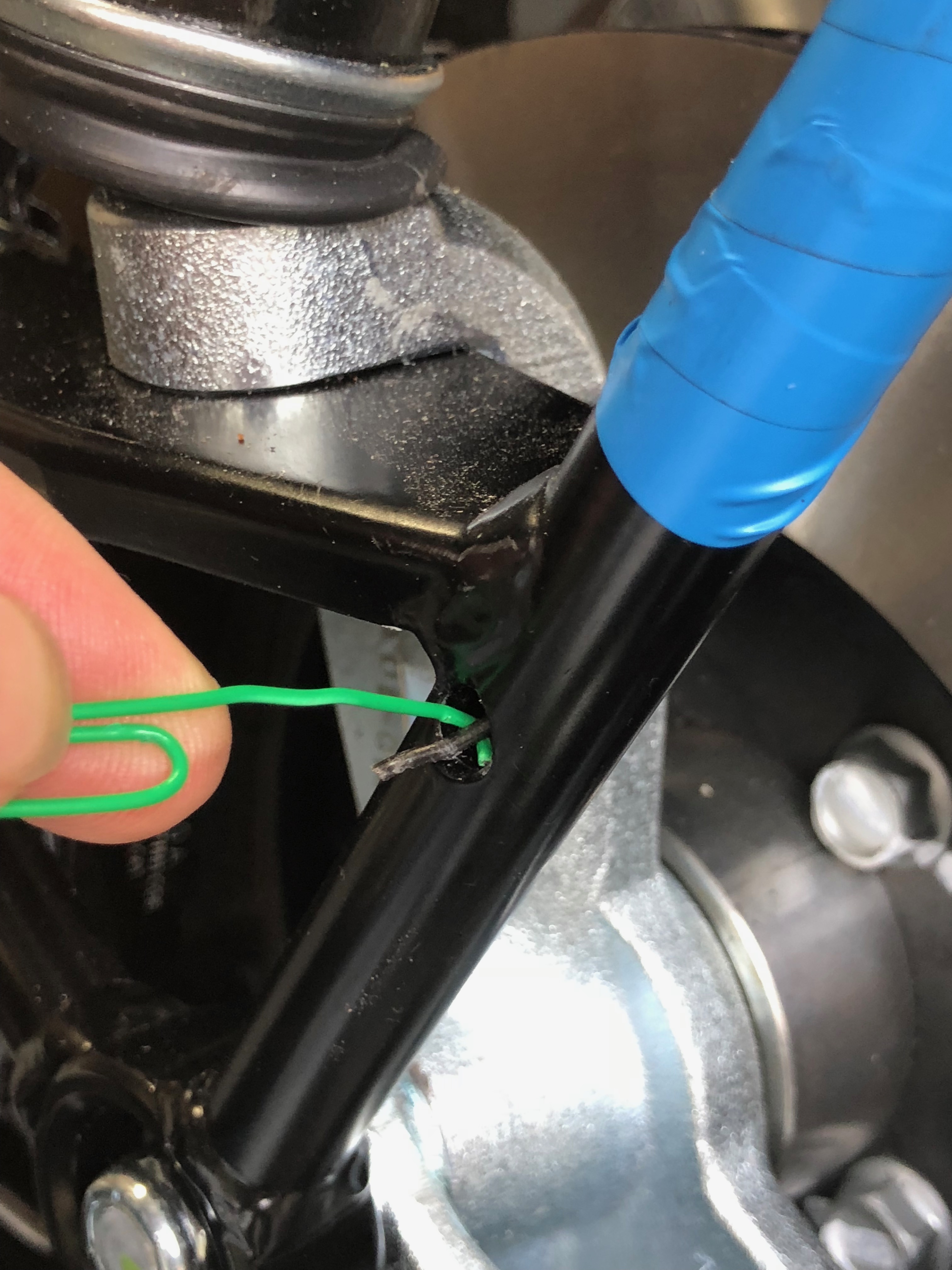
- Insert pull cord through wing stay – a thin piece of coated wire in my case
- Add approx 15cm of 7mm heatshrink to the wires nearest repeater
- Thread repeater heatshrink/wires through 16mm hole I’d cut in the wings
- Thread heatshrink/wires through wing stay (using pull cord)
- Add grommet to wires and insert where wires exit wing stay
- Add long piece of 7mm heatshrink to wire ends
- Insert heatshrink through grommet added to wing stay (using lubricant to get the heatshrink as far in as possible)
- Apply heat to heatshrink
- Bond wings to wing stays
- Cable-tie wires to rear arm of top wishbone
- Bolt earth lead to chassis (there’s a threaded hole on both sides where the front t-piece is bolted on both LHD and RHD cars)
- Wire repeater signal wire into the econoseal connector
Here’s a few pics of some further tidbits…
A paper-clip worked better than tweezers at getting the pull cord out of the wing stay…
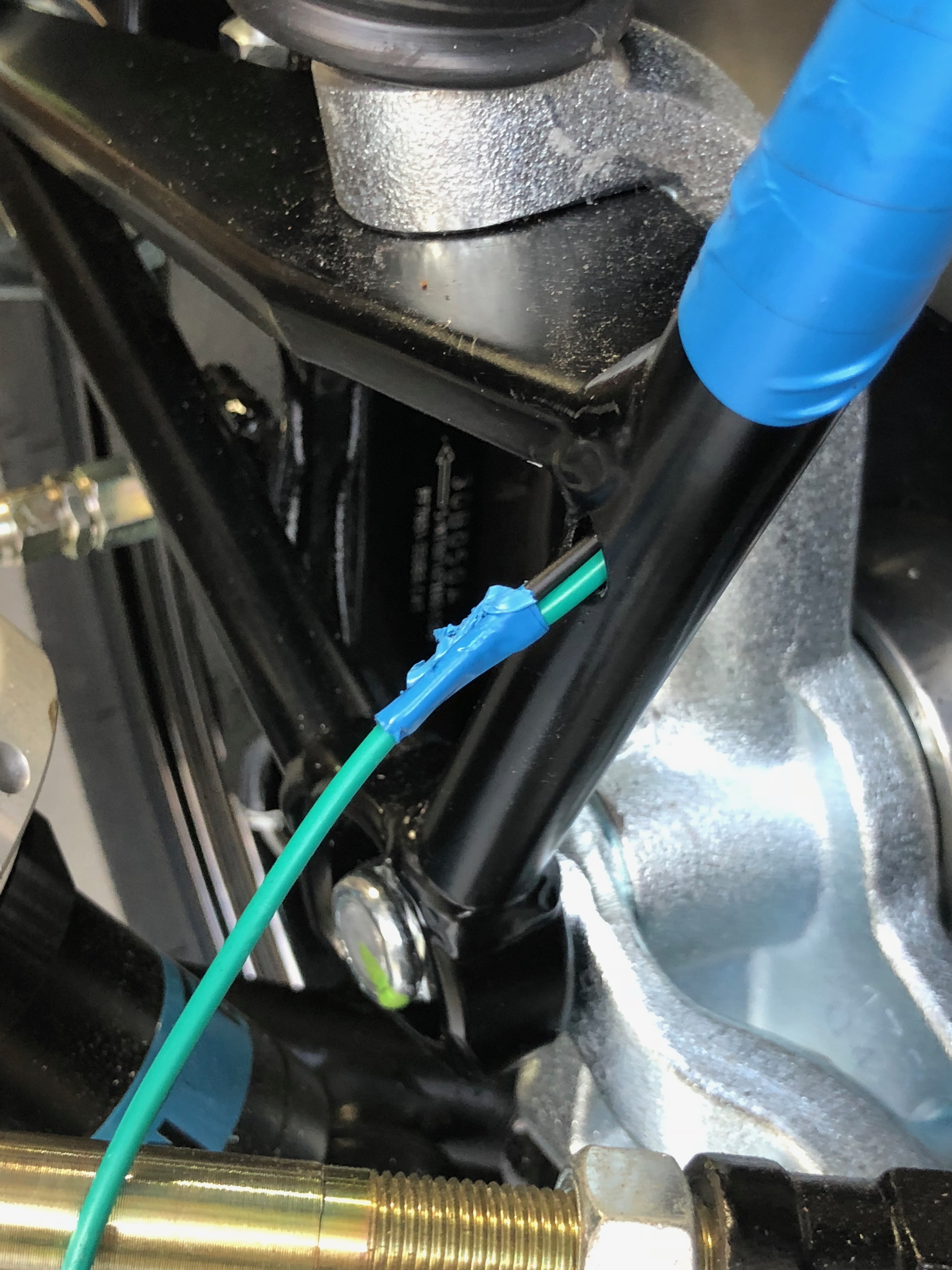
Tape the repeater wires to the pull cord…
I removed some material from the back of the grommet I used for the wiring exit from the wing stay. This allowed the grommet to go in more easily, especially as I’m feeding two wires down the tube where Caterham only do one…

I did a test run again without the wings in the stack…
Ok. So at this point it was still early in the day and I was being nervous about attaching the wings to the wing stays while having to work around the car all day – I might knock them as I move around. I still have 4 days until the PBC (Post Build Check) and so could afford to wait until the end of the day to stick the wings onto the stays.
Onto something else then…
Engine LHS Wiring Tidy-up
Next up was to spend a couple of hours (2:15 to be precise) sorting out the wires one the LHS of the engine. I’m happy that I don’t have anything that’s going to mean I need to pull this apart again, so time to tie it all down for IVA.
There’s a few things going on with the wiring under the intake manifold:
- Oil pressure sender
- Alternator
- Mystery unterminated spade connectors
- Engine to chassis earth lead
When I started on this, it was all just hanging about still. The car had arrived with some of the alternator wiring half held in a P-clip and the oil pressure sender wiring was just wrapped around the oil filter.
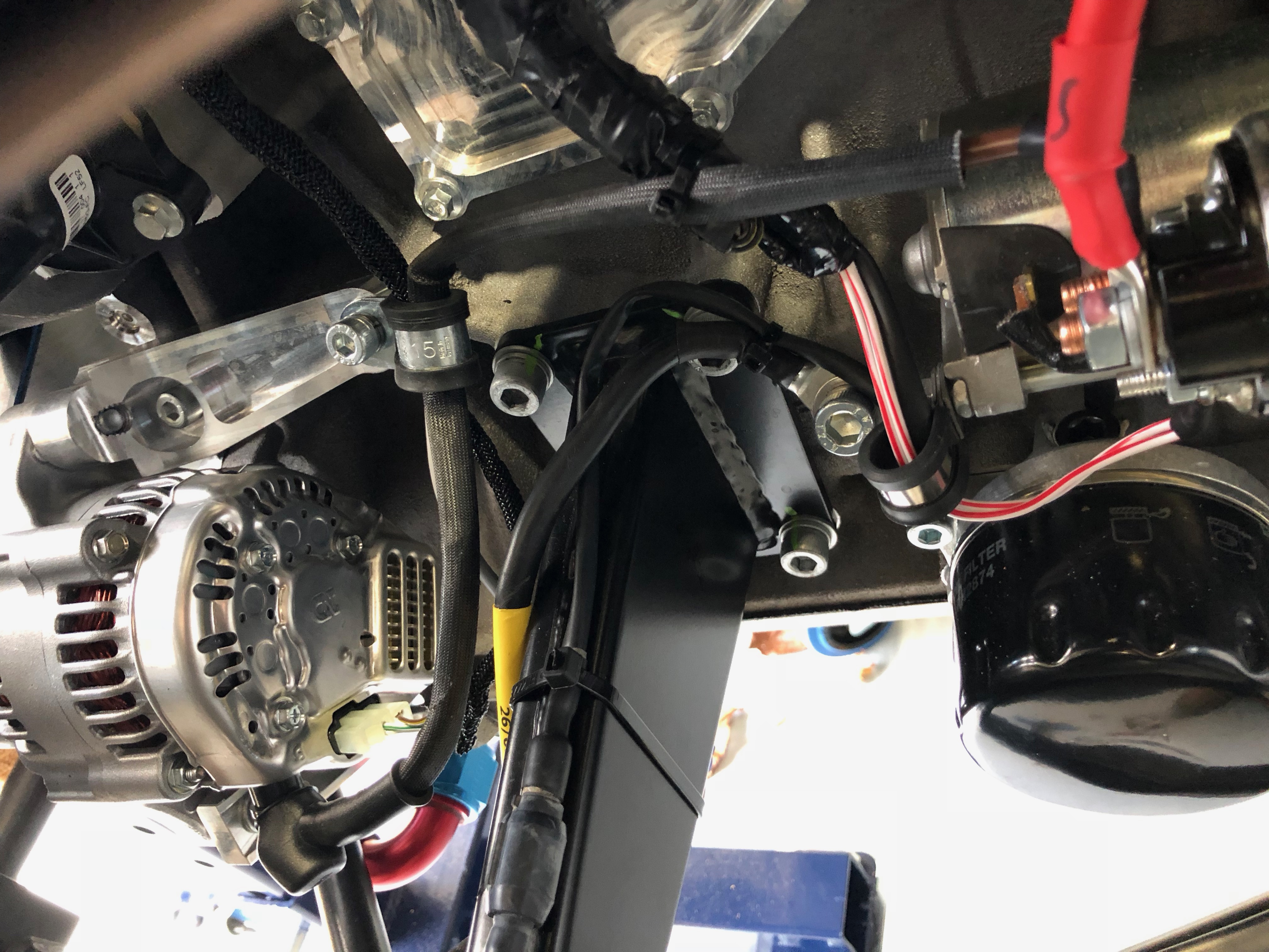
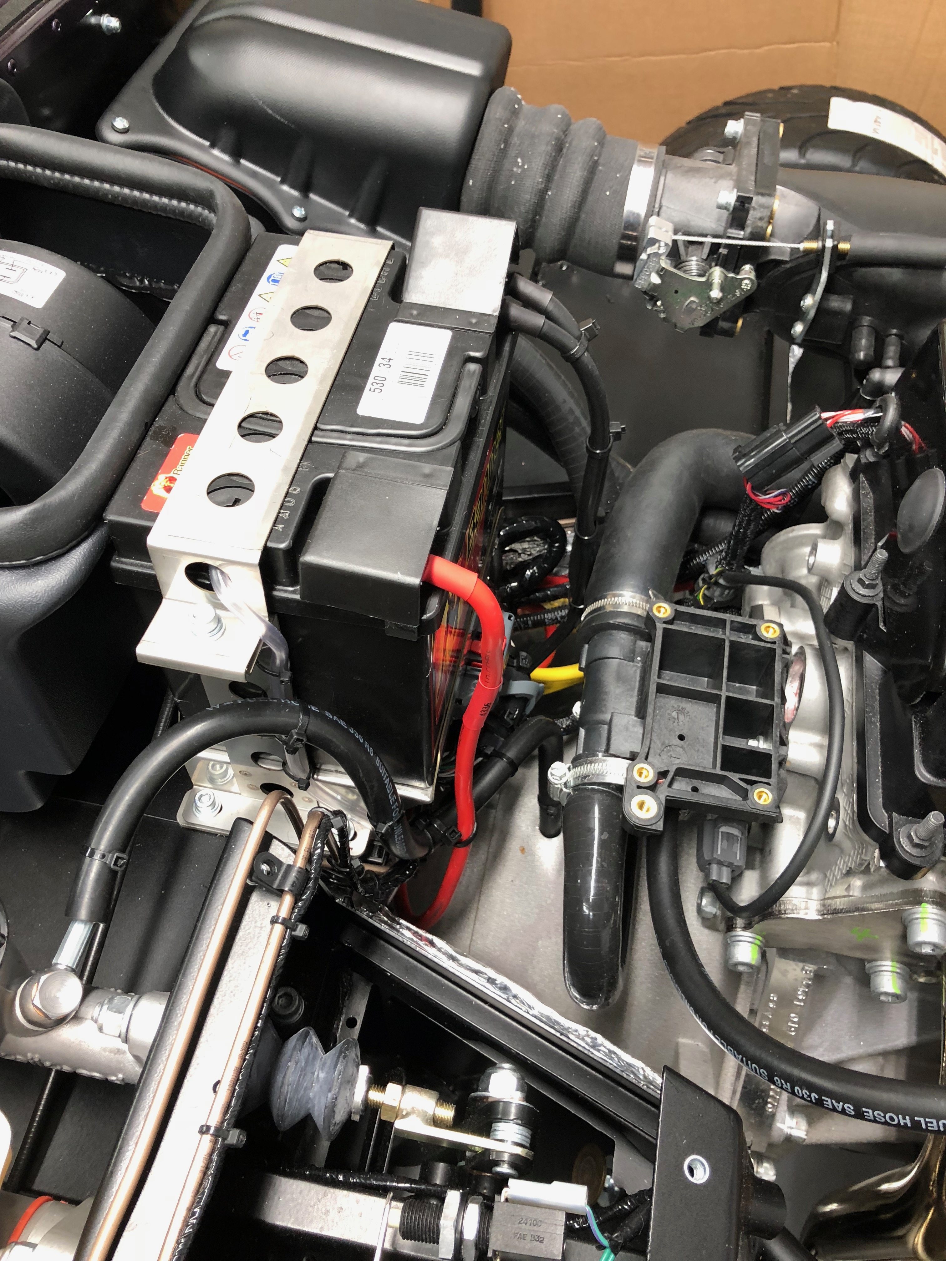
The picture below summarises where I got to…
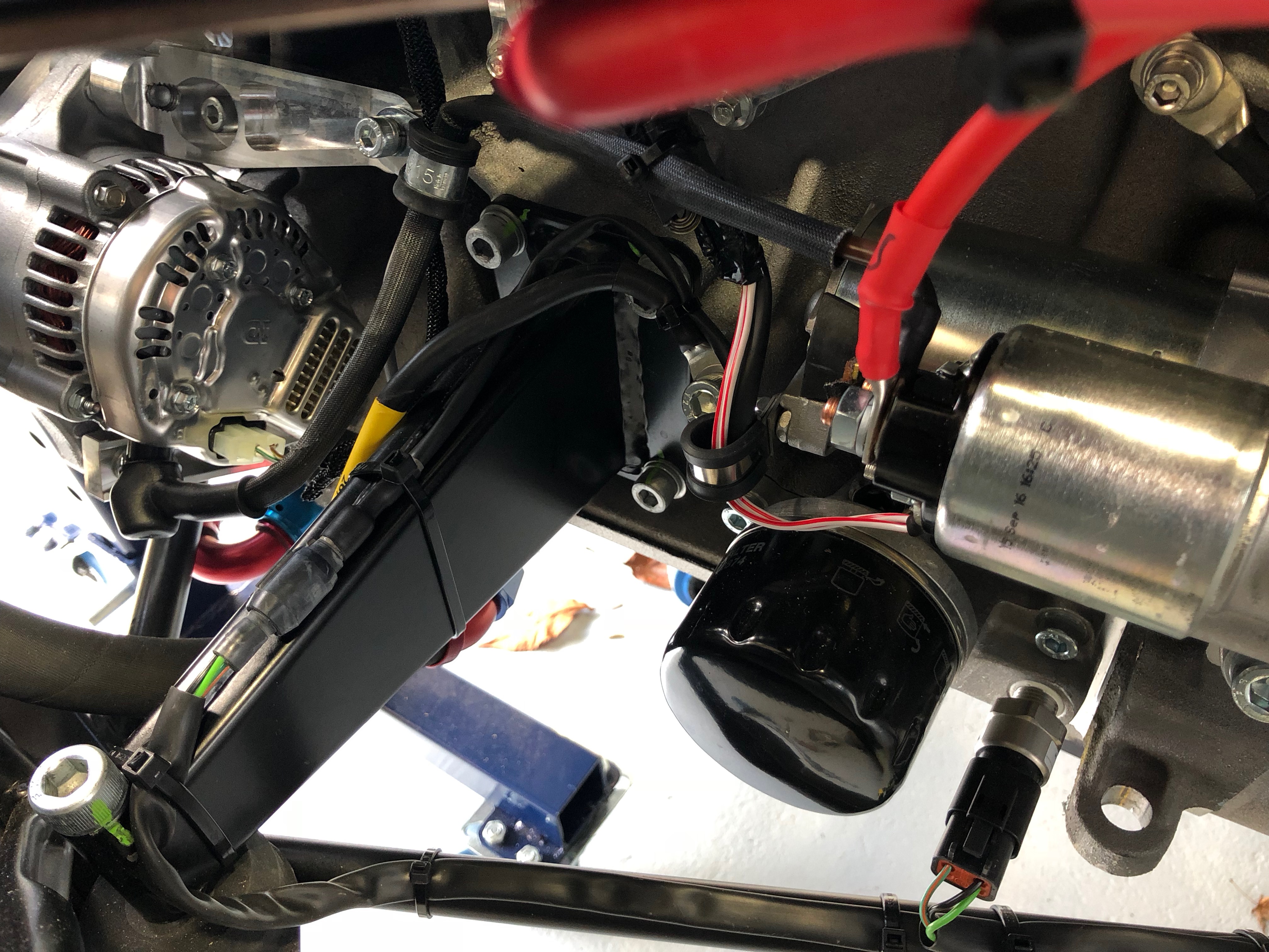
In the picture above, here are some salient points:
- The P-clip (top left of pic) was only half attached when the car came. I attached both eyes of the clip and kept the +ve lead from starter to alternator included in the P-clip. I also added the wire that runs from the timing sensor on the bottom of the RHS of the block. This wire runs under the front of the engine and then up the LHS of the block. I have a picture of that sensor and will add below
- I added a P-clip (centre right-ish of pic) and ran the red/white wire from the starter motor through it
- The oil pressure sender wiring is long – even for an SV chassis. You have to run the wiring along the engine mount (from top right-ish to bottom left of pic), down onto the chassis rail (bottom left), across the chassis rail (bottom left to bottom right) and then “lose” the excess wiring by doubling the heat shrunk covered wires back on themselves and then into the sender (to the right of the oil filter).
- Make sure the boot is on the +ve cable going into the alternator from the start motor.
I’ll need to come back to this area later and add IVA plastic caps to the various nuts that protrude into this space.
As for the mystery spade terminals in the loom on this side of the engine (I think they may be something to do with oil temp… maybe??), I just taped them up into the loom and cable tied it all back together again…
Mirrors
Mirrors next…
I’m presenting the car to the IVA test without the doors or hood. I didn’t want to get into the complexities of those extra bits in the test… less is more.
Irrespective of this (the side mirrors still need to go on the sides of the windscreen), the side “wing-mirrors” need be fitted to the windscreen – not the wings! 🙂
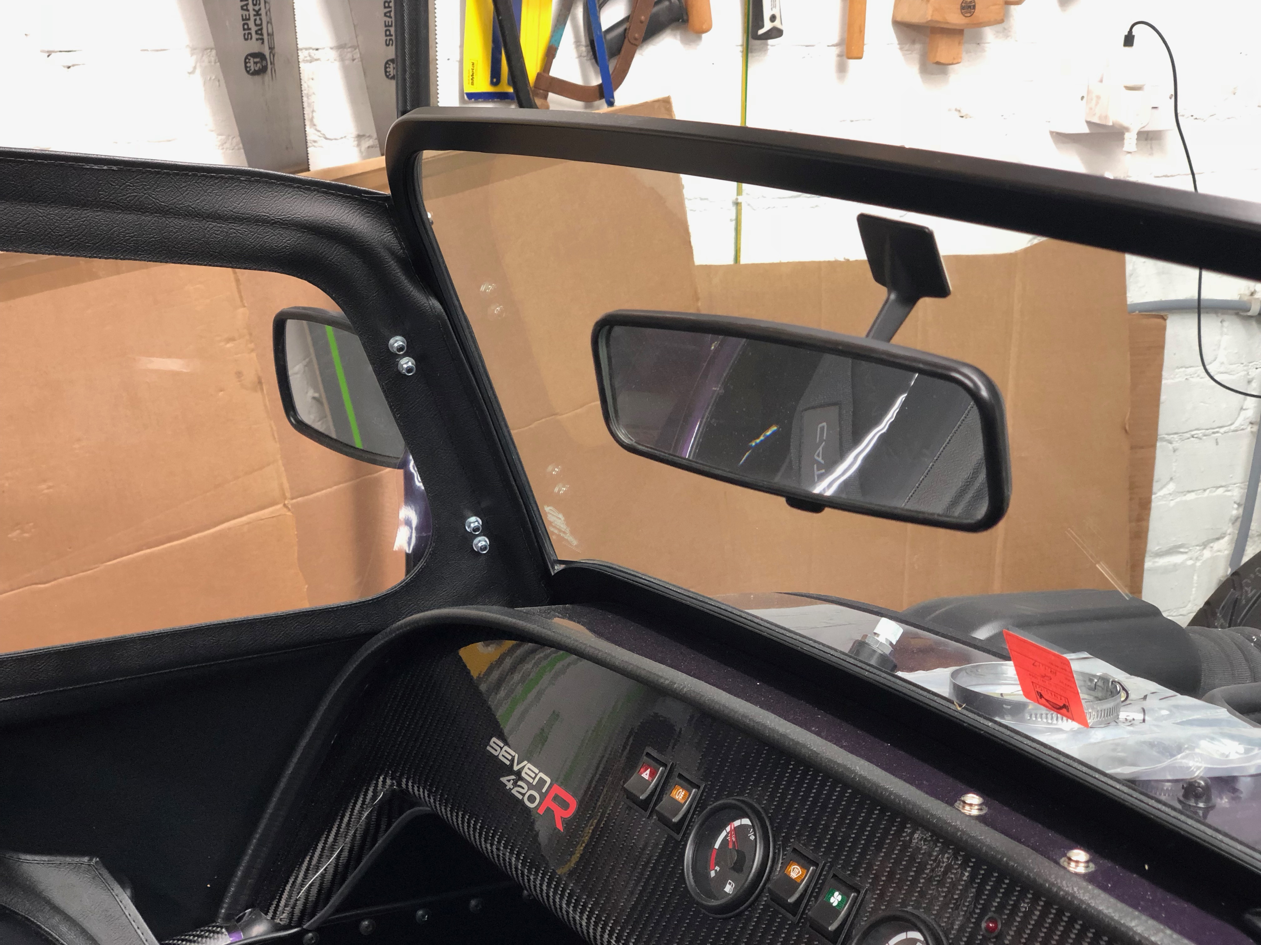
First up though is the rear-view mirror. Simple job to take the 3M protective paper off the back of the mirror stem and fit it to the top of the windscreen. There are lots of mods that can be done to improve the rear-view mirror options but I was going for an IVA pass and so wanted a bog-standard mirror to get through the test.
Side mirrors next…
Perhaps its me but I didn’t find the build manual very helpful when figuring out what to do with the side mirrors. As I mentioned above, the side mirrors need to be attached to the windscreen for an IVA pass. Once the IVA is done the accepted wisdom is that these mirrors are moved to the driver’s/passenger’s doors. The idea being that with the mirrors installed on the windscreen the doors won’t open far enough for the doors to rest on the bonnet – where they will stay put and you can then more easily get into/outof the car. With the mirrors installed on the windscreen the doors only open half way and you have to hold them there so they don’t fall back into the closed position again.
So… the mirrors need to be installed on the windscreen.
Now, how do we do that?
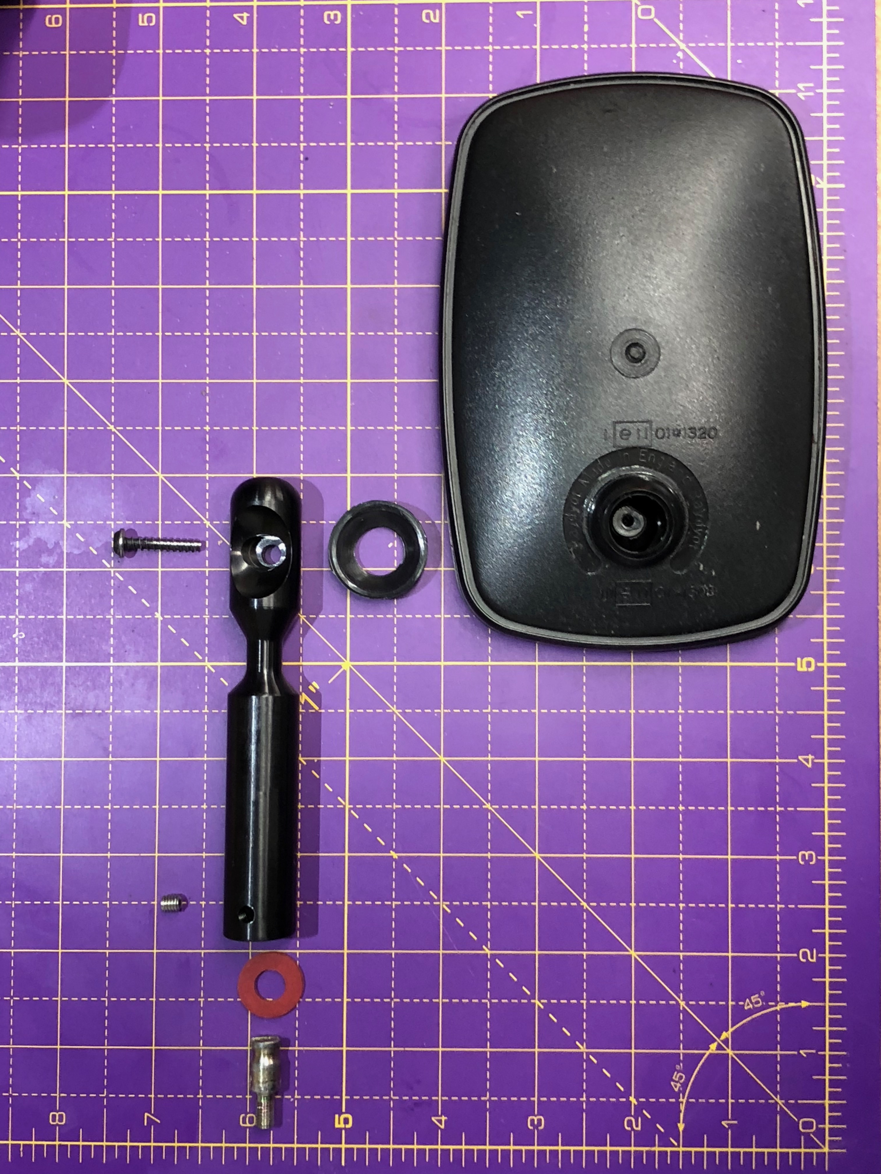
The mirrors are supplied with the stems used to attach them to the doors, not the stems used to attach them to the windscreen. And… in order that the mirrors be adjustable the mirror frame is attached to a stem using a ball and socket arrangement with a screw running through the stem, socket and ball to tension the whole thing (see exploded view of the parts below). The ball also has a short stem of it’s own that the screw thread goes through.
Now, of course, when you take the screw out from this tensioning arrangement, the whole thing falls apart. And to make things a little tricker, the ball floats in the mirror frame so that when try and put the screw back in the ball just rotates in the frame.
Now, because you’ve not had a chance to see all of this before, you’re left with a bunch of bits that need to be assembled onto the new stem.
There’s a trick…
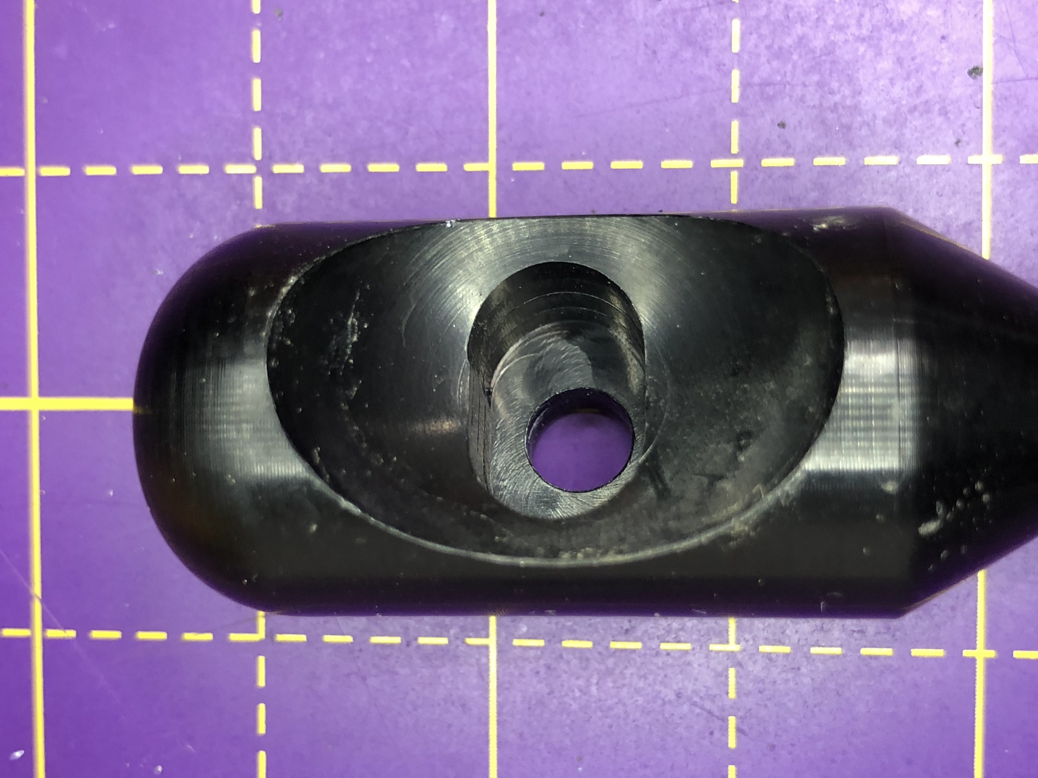
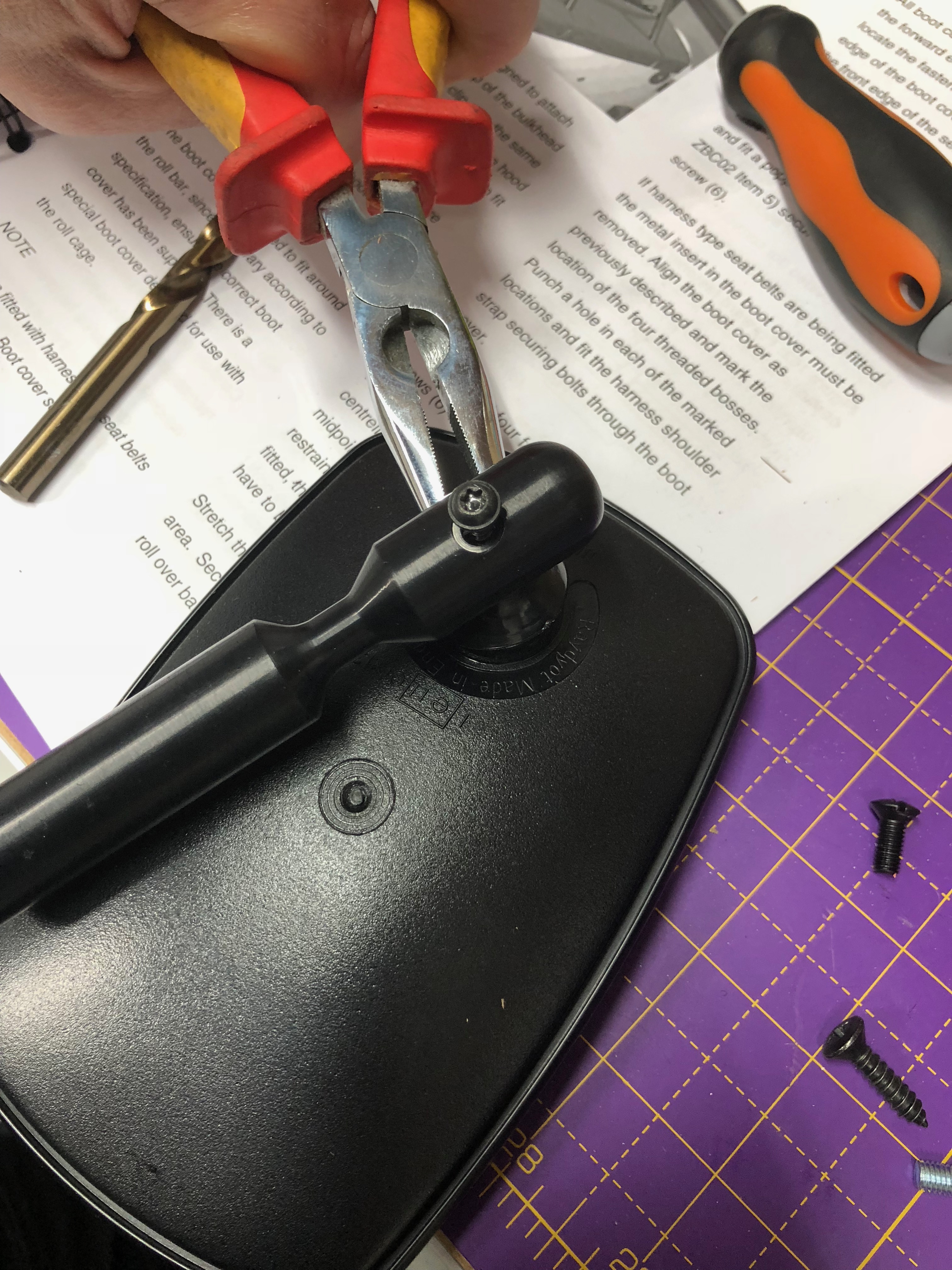
As I mentioned above, the ball in this arrangement has a stem on it… and on that stem is a flat on it’s side. You use the flat on the ball/stem to lock the ball/stem into the larger stem – it will all make more sense with some pictures below. That way you can do up the torx screw without the ball rotating all the time. I needed a pair of pliers to get the whole thing going, before the flat on the ball/stem can engage in the larger stem slot.
That’s a lot of words… but we all know a picture paints a thousand words… so here’s some pictures:
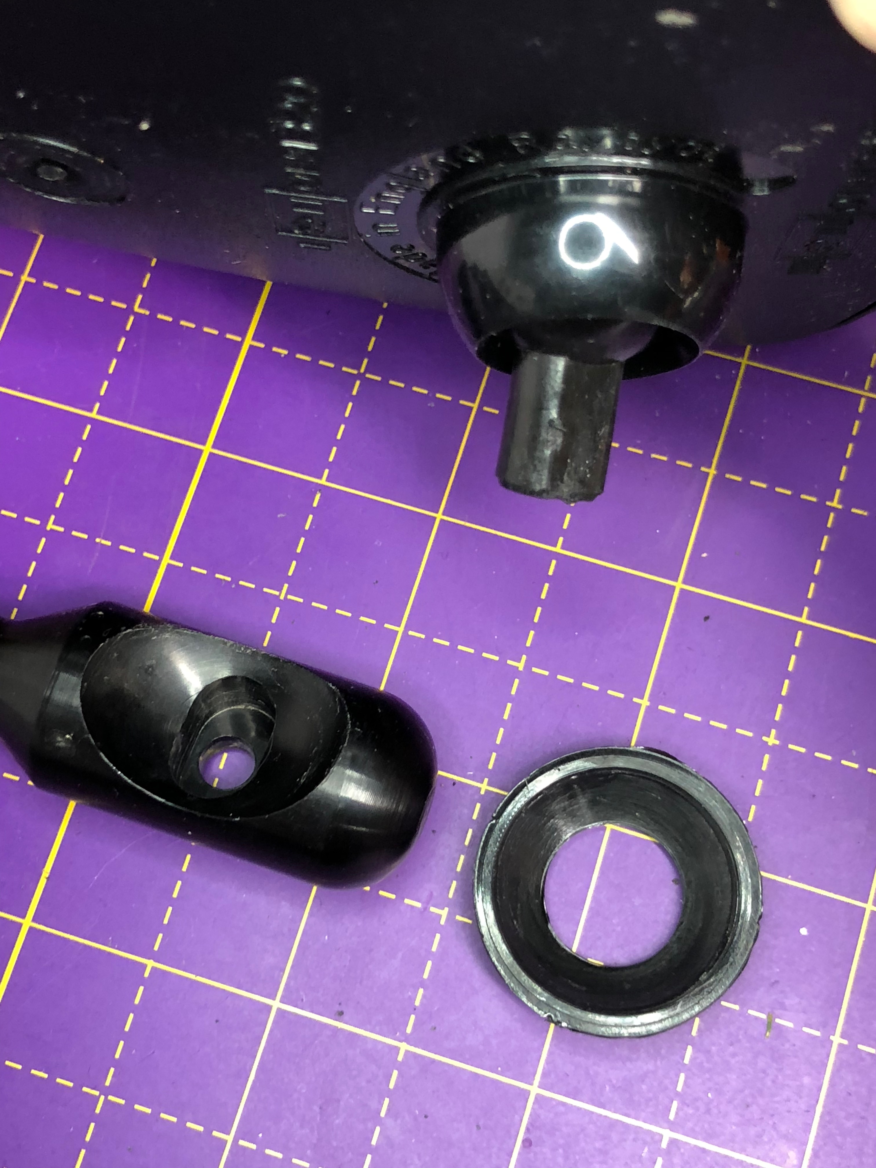
This is how it’s all arranged in an exploded view…
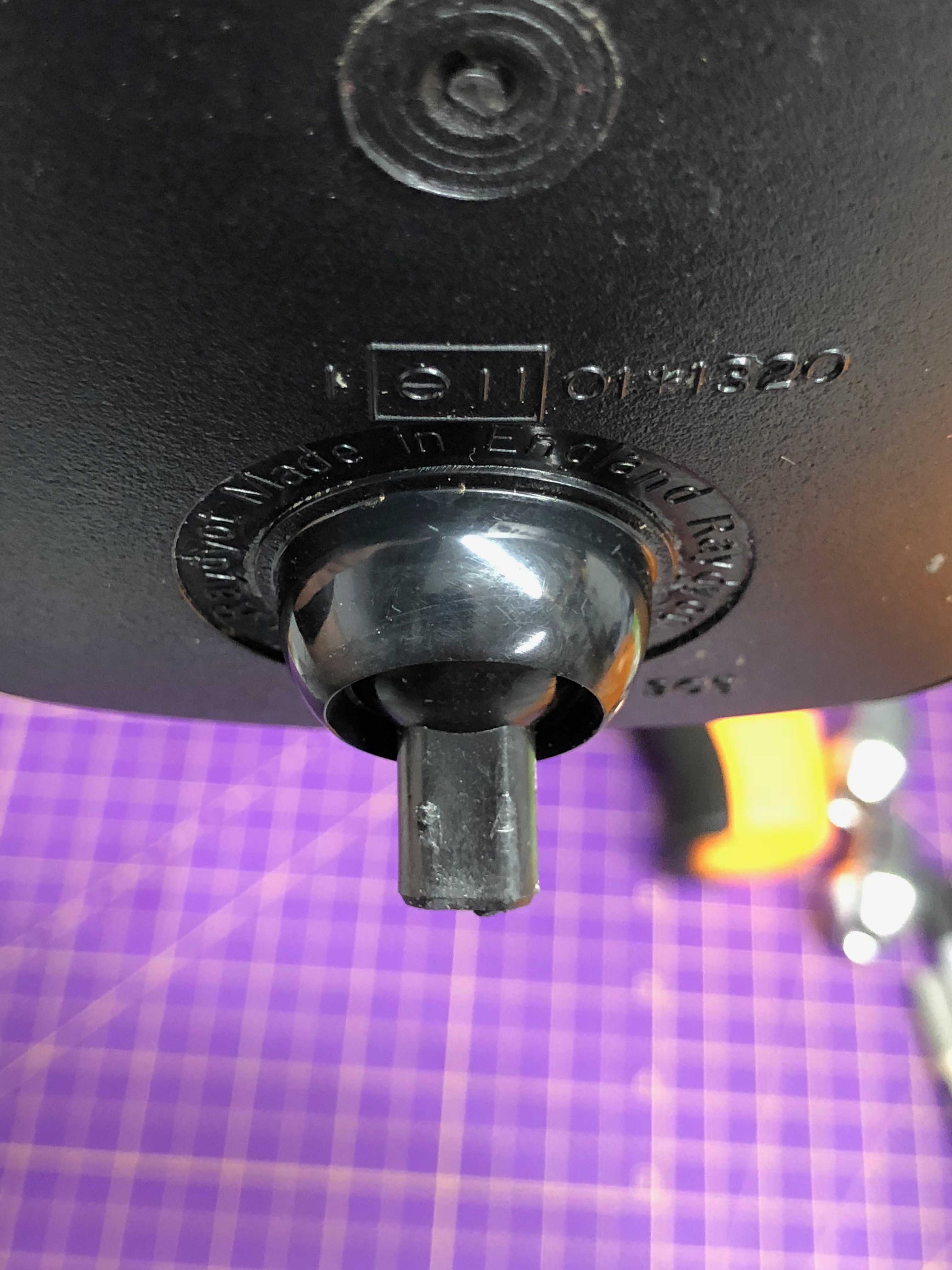
Here’s me using some pliers to get the torx screw started back in the assembly…
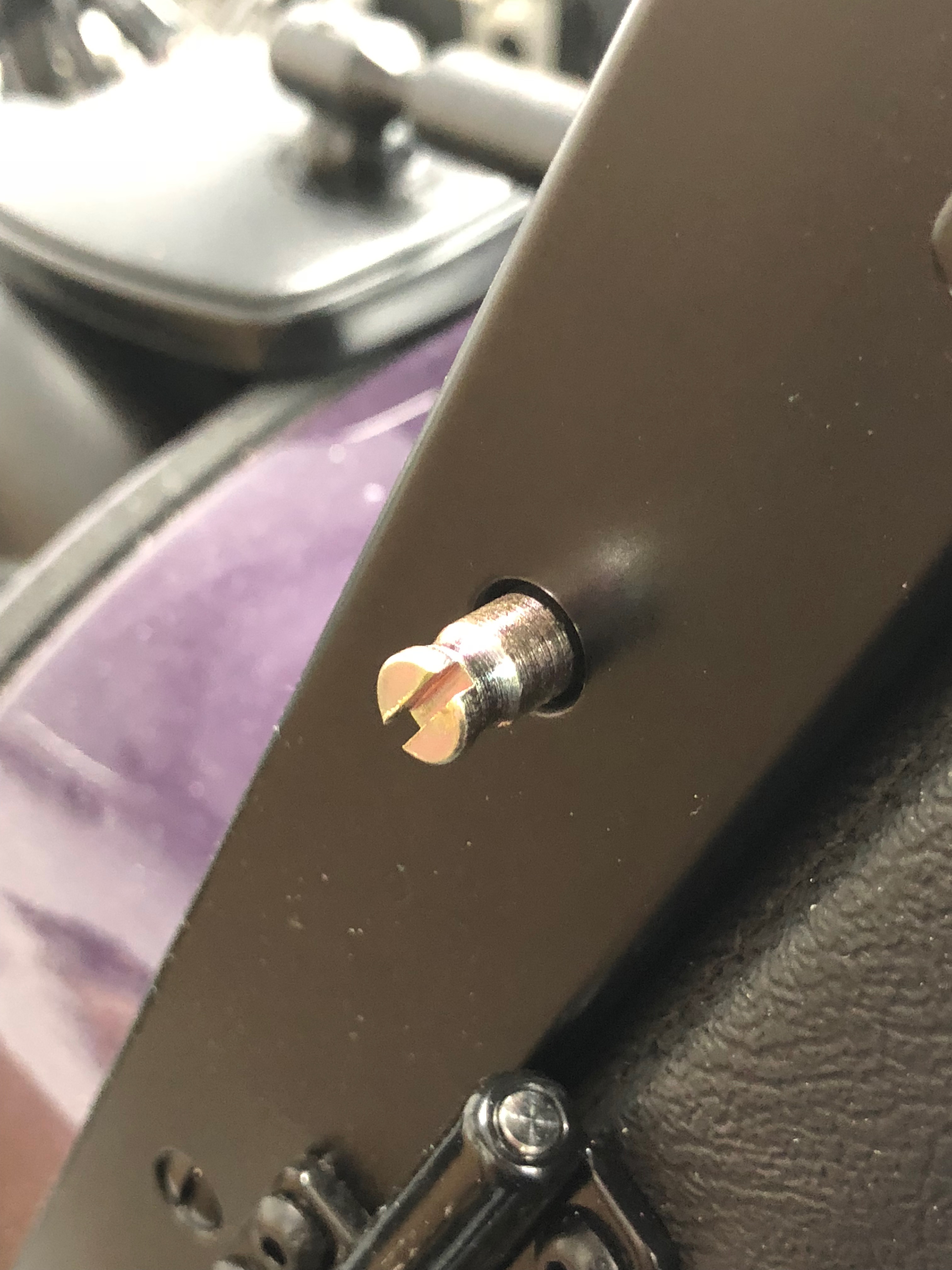
It’s then a simple case of replacing the middle screw on the windscreen sides with a stud fixing…
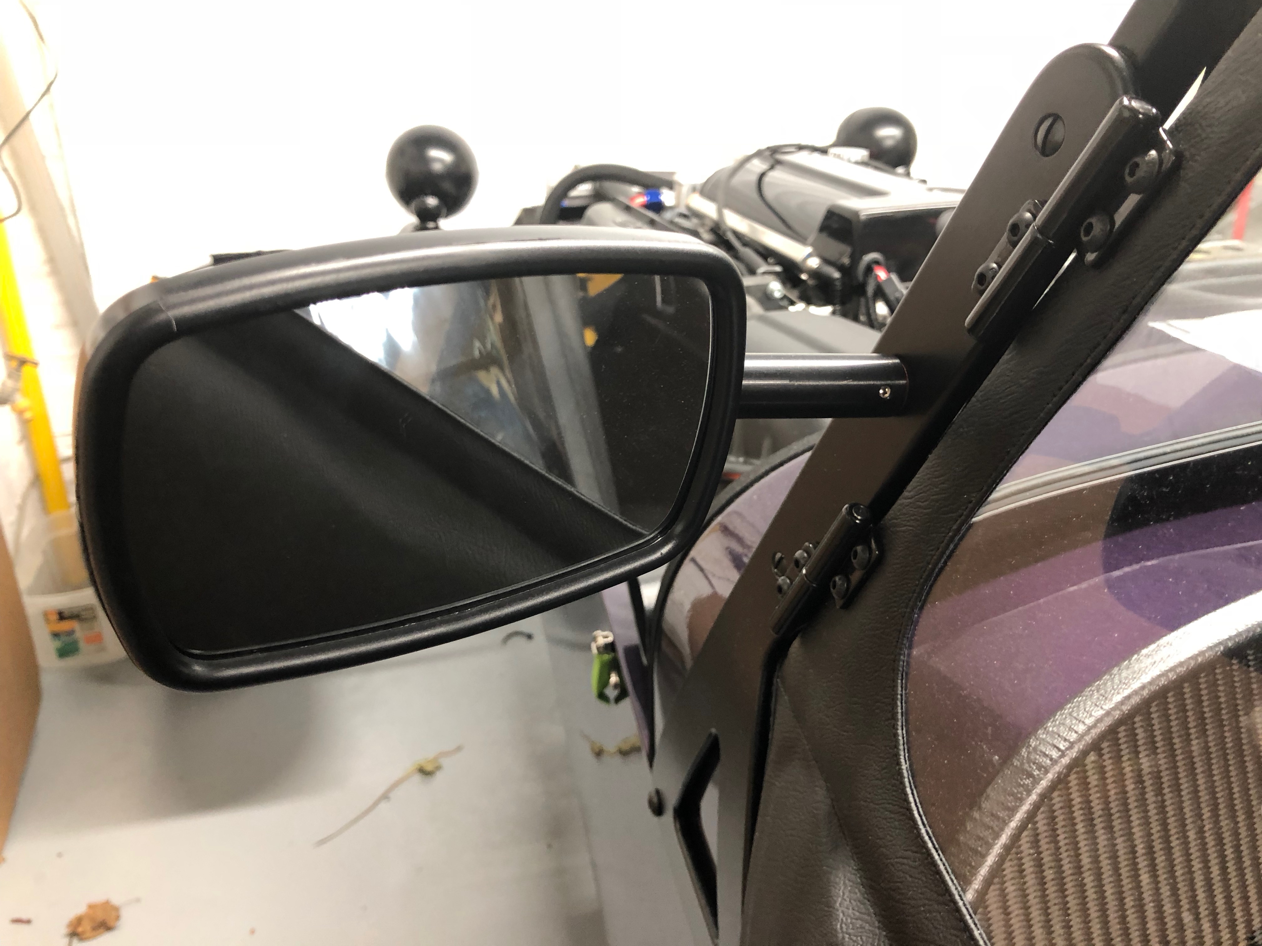
Here’s a finished wing mirror ready for IVA…
That was a lot of words and pictures for such a simple part of the build. I hope it helps any future builders.
Like I said… lots to get done today… onwards!
A Ding
It was at about this point that I had a bummer of a moment. I was rushing around a bit and managed to drop a pump-clamp onto a rear wing – bummer!
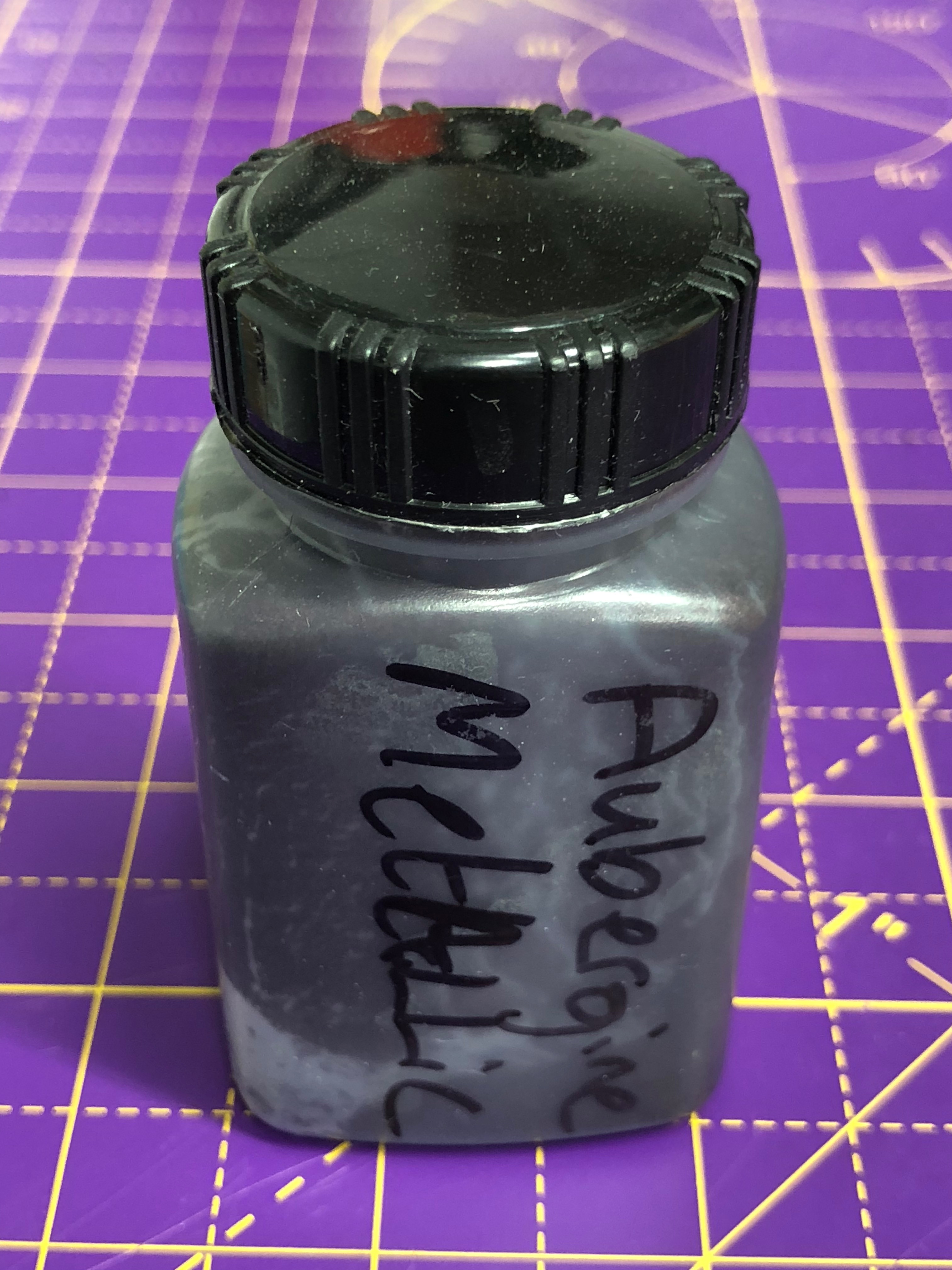
I touched up the resulting ding with some of the spare paint that I’d been supplied with in the kit. I’m not too precious about the whole “pristine” thing but its a shame to have dinged the paintwork at this point.
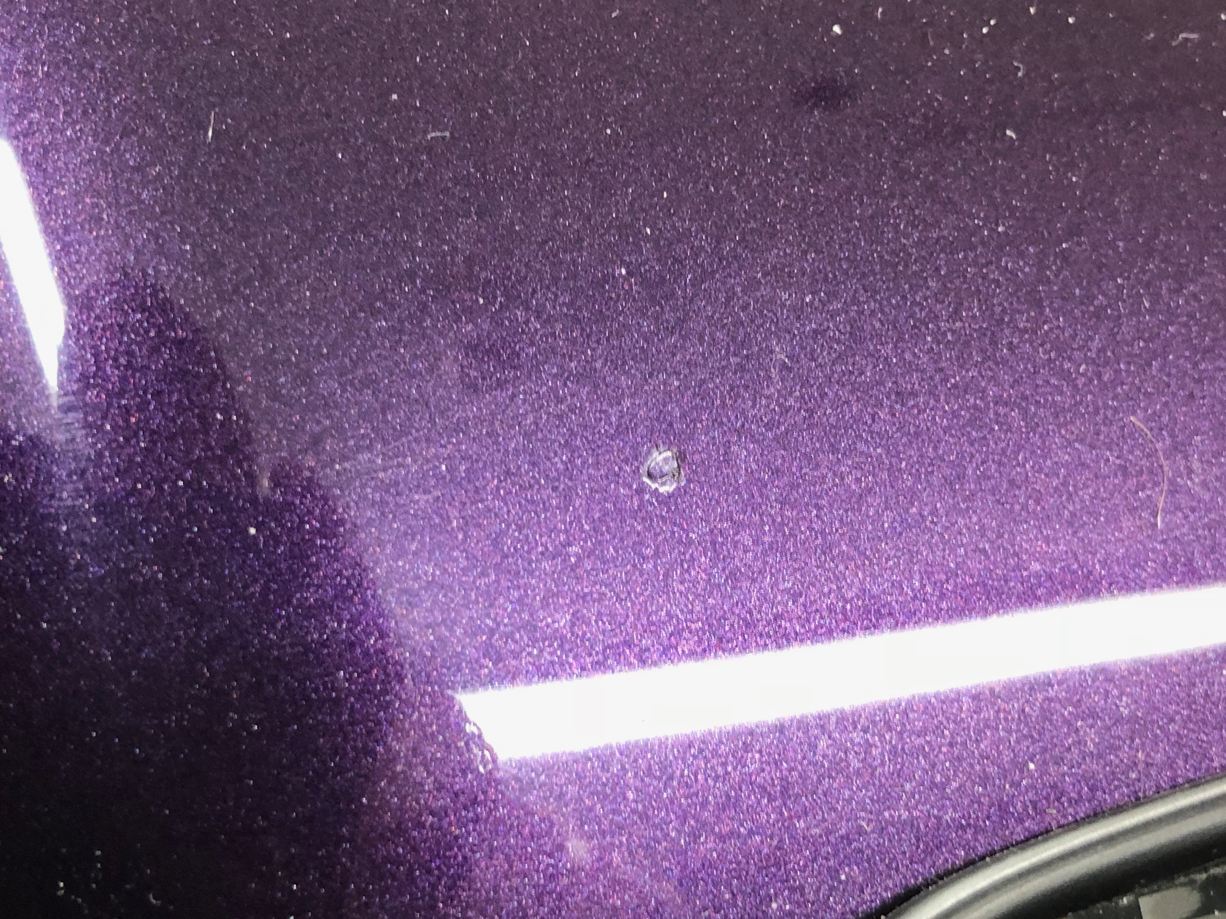
I guess I was being a bit sloppy not to cover the rear-wings with some cardboard or bubblewrap when I’d installed them. The PPF (Paint Protection Film) I’m proposing to add later would have protected that particular point, but it doesn’t cover the whole car.
Front ARB Tidy-up
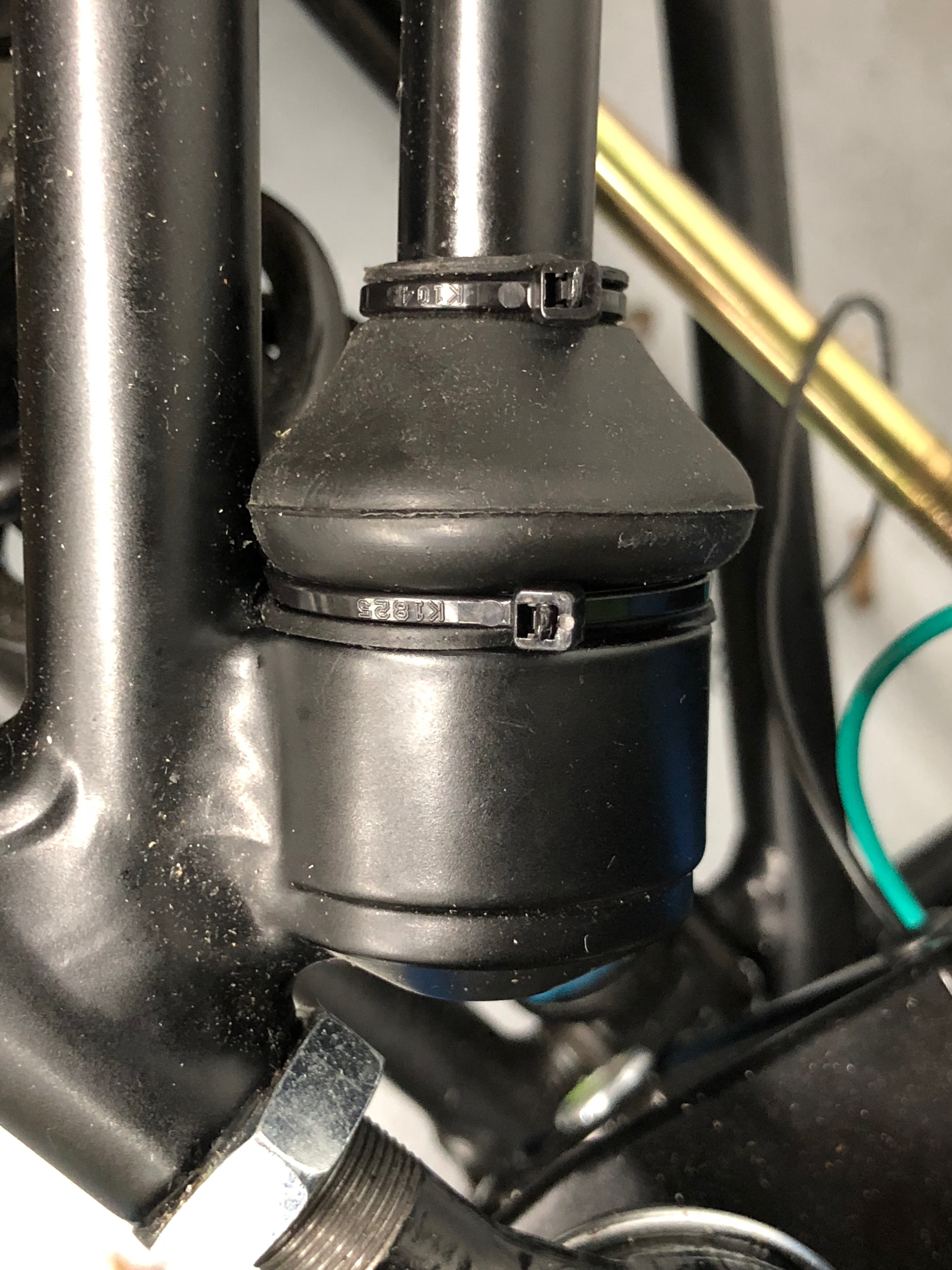
For those of you following closely you’ll remember that I had to disconnect the front ARB (Anti Roll Bar) in order to add grommets to the front light stem wiring – after my bonnet drop-off visit to Caterham, Crawley.
A simple job was then to refit some 2mm x 200mm cable ties. I’d had to order these in specially, they’re narrower than anything else in the kit and there are only enough in the kit to do this job once… and I am doing it twice!
Air Filter
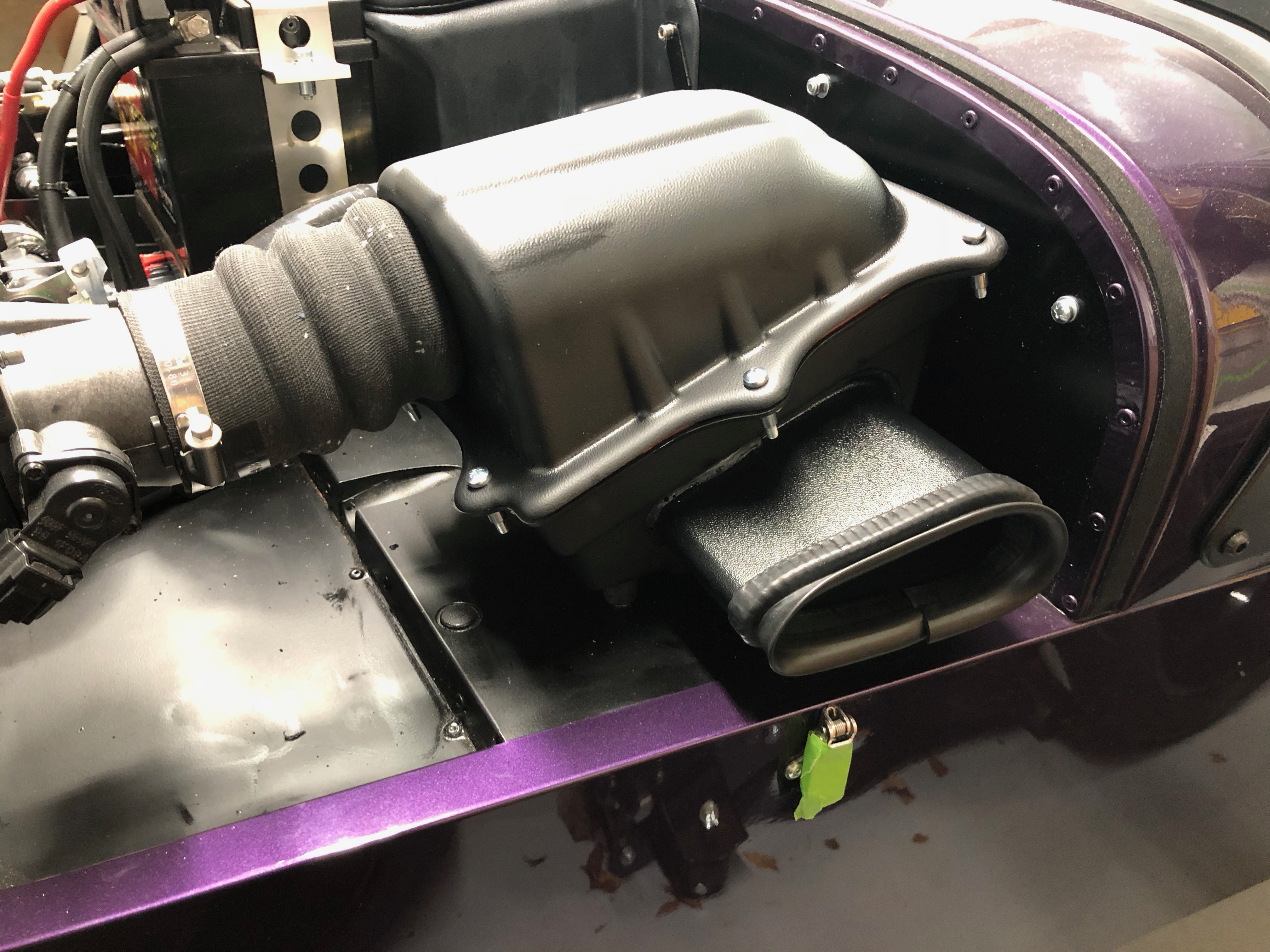
Next up is the air-filter. There’s almost nothing in the build manual about this step, but it’s fairly simple. The filter is, of course, inside the black box…
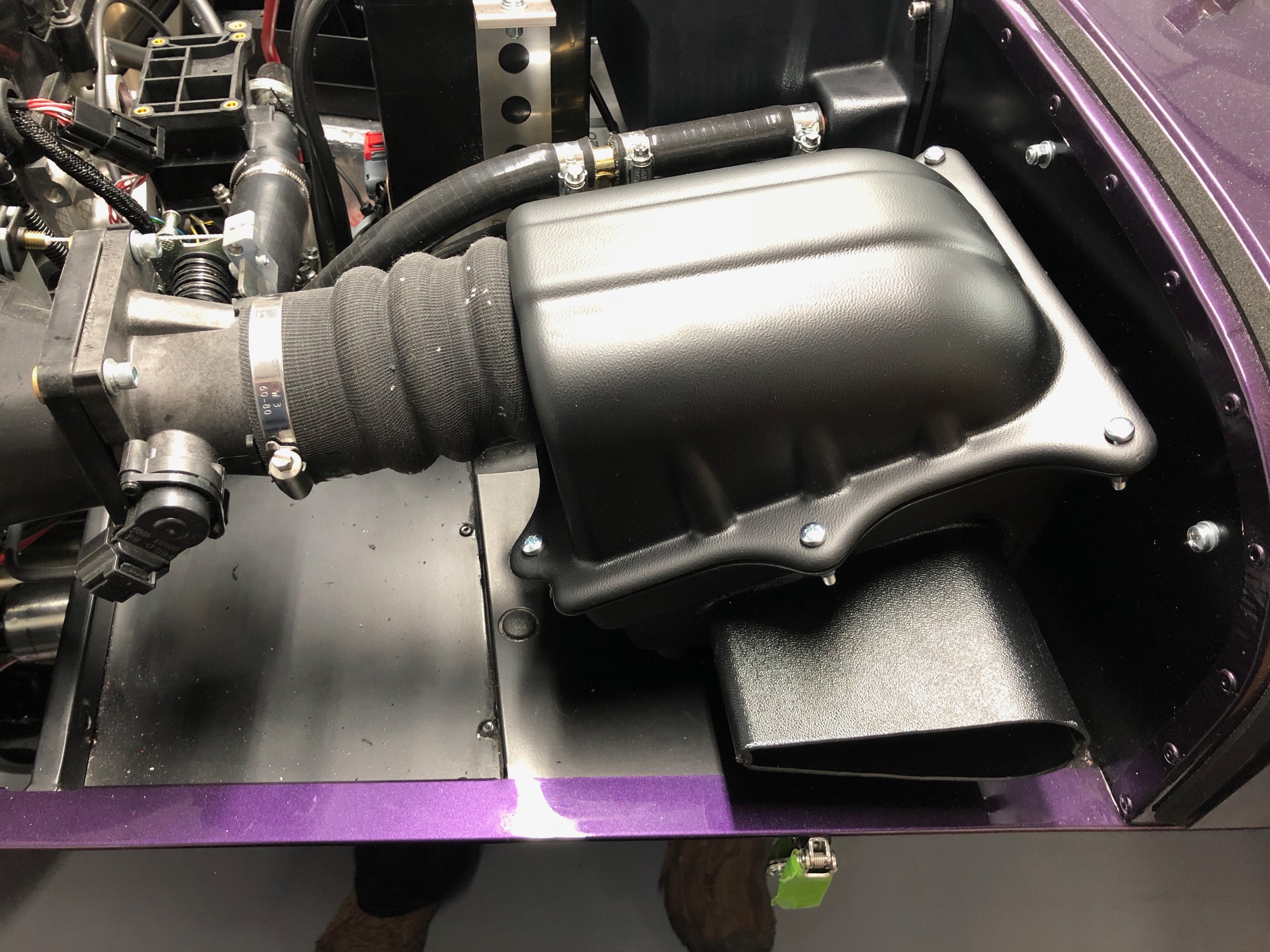
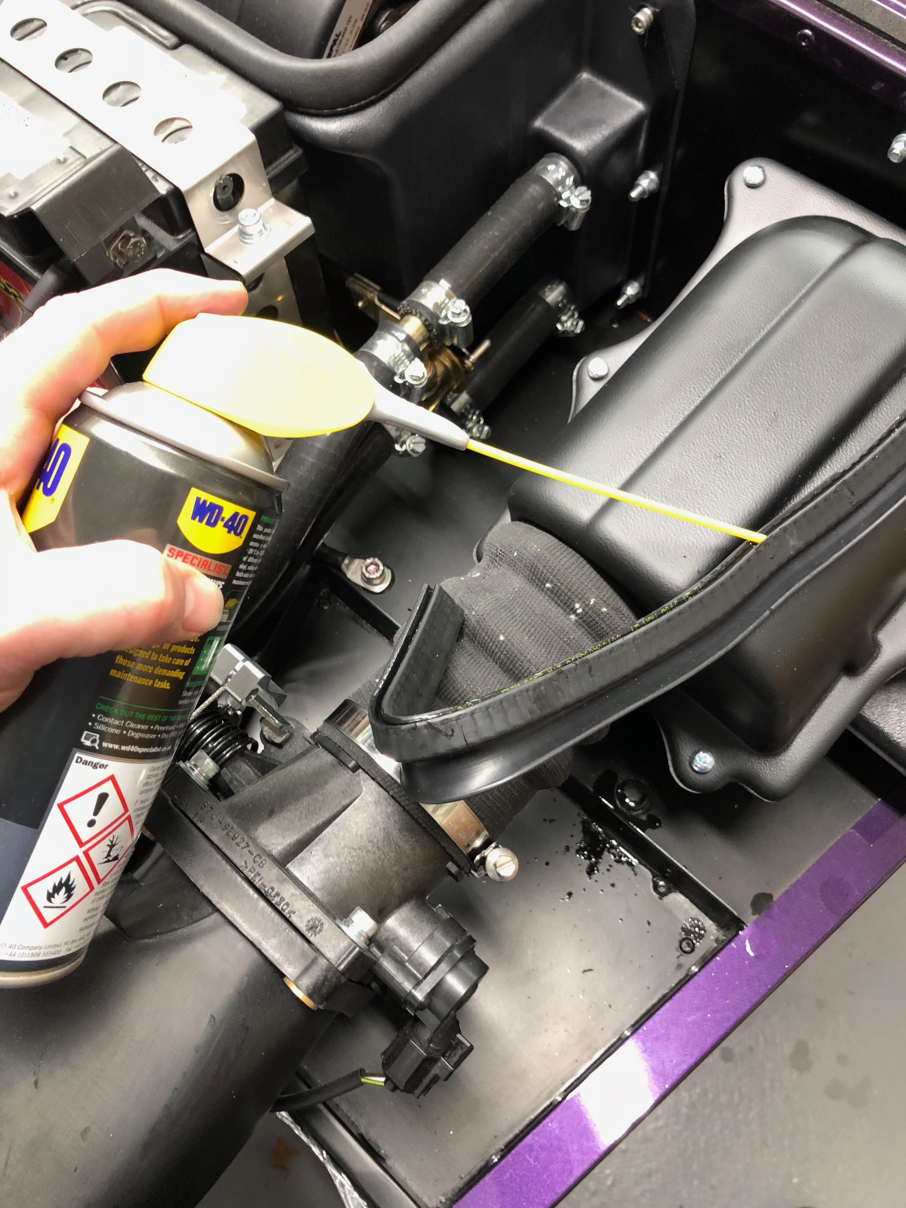
Next it’s the air intake trim, that seals the air-filter assembly to the bonnet. After a bit of research it does make sense that it fits with the flange making a funnel but there’s no pictures or instructions in the manual. It needed lots of lubricant and “pre-shaping” before it would go on. The trim is constructed like the IVA trim for the dashboard, i.e. it has a metal strip moulded into its centre and so can be “formed” to get the small and large radiuses needed to attach it to the filter assemebly…
Odds and Ends
Next up a couple odds and ends that I’ll lump together…
First is to attach and cable tie the 5/16th hose used to protect the braided clutch hose…
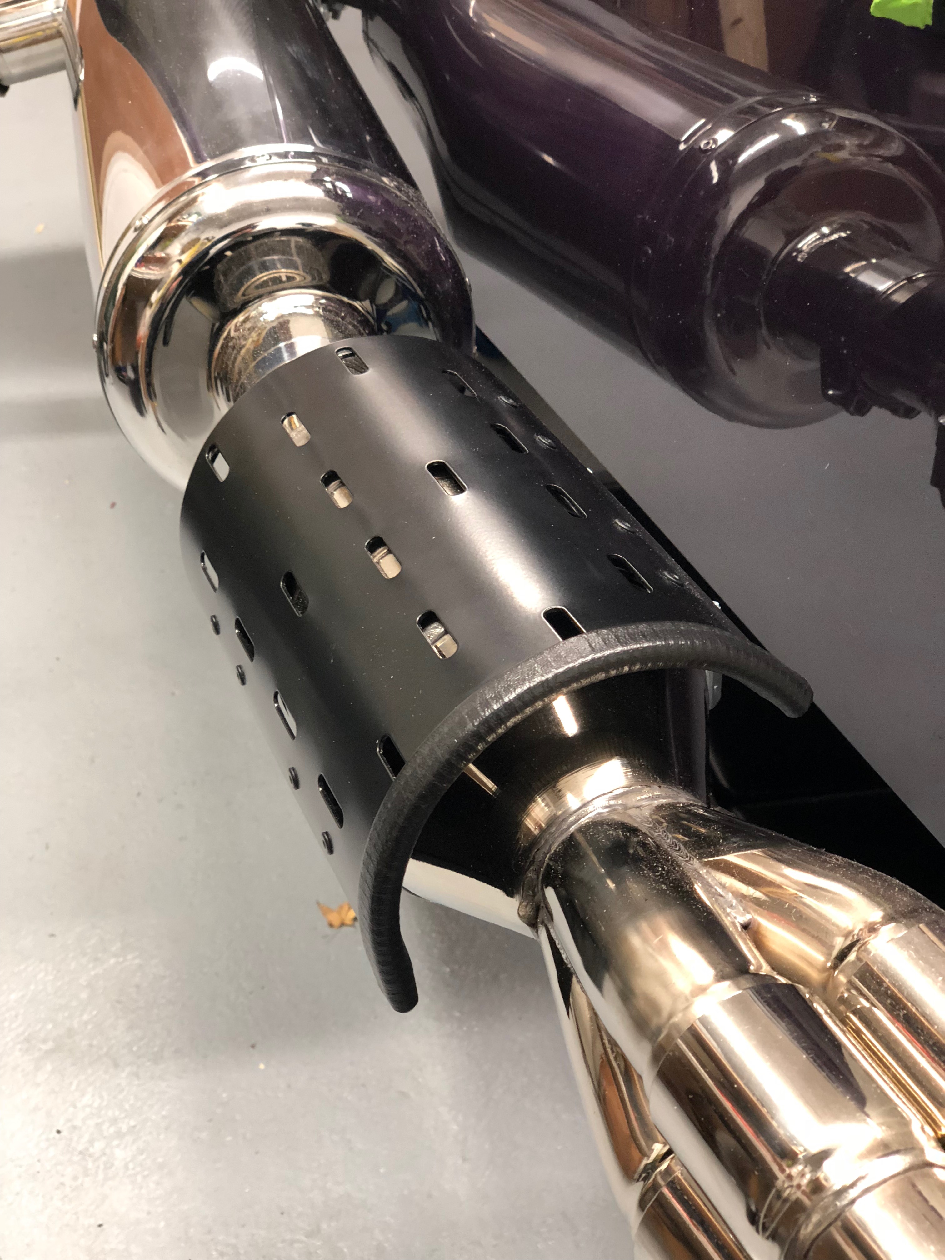
… and add the IVA trim to the catalytic converter cover…
Windscreen Wipers
Another 10 minute job to add the windscreen wiper blades to the windscreen wiper stems. Its important to have run the wipers at least once through a cycle prior to attaching the blades. The windscreen wiper motor and cams/rods could be installed part way through a cycle in the factory and putting the blades on at the wrong point in the cycle could drive them into the bodywork or off the side of the windscreen.
Here’s a video of the comedy wipers in action, I still need to bend them some more so they sit closer and more parallel to the bottom of the windscreen…
Tightening Rear Hub Nuts
Penultimate job today…
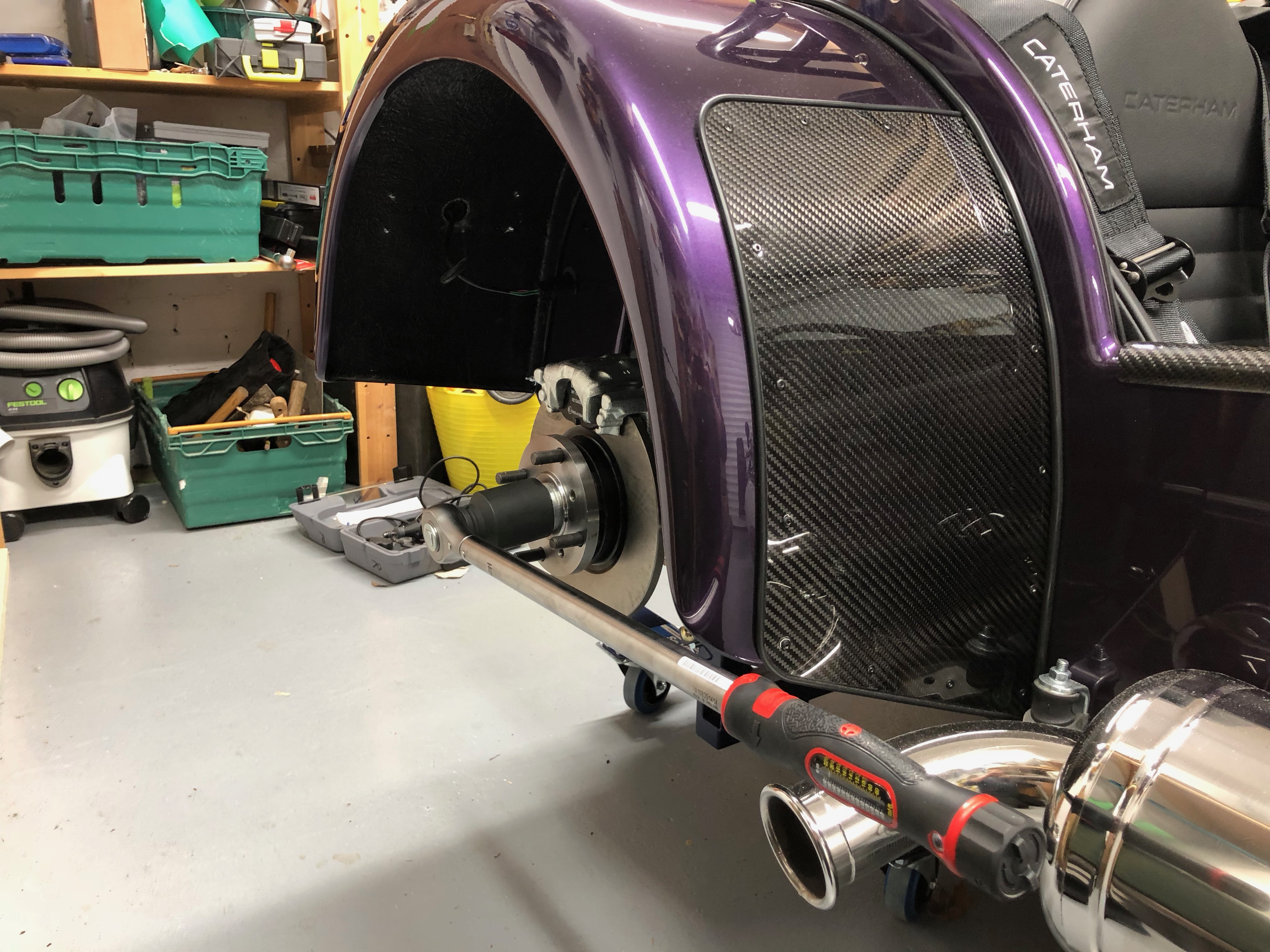
The rear hub nuts need to be tightened to a pretty hefty 274Nm, to make sure they don’t allow the rear wheel assembly to come apart and therefore have a wheel fly off into the distance (happened to me before, but that’s another story!).
Because of the magnitude of the torque needed to tighten up these two nuts (one on each side, one left hand thread, the other right hand), it’s almost impossible to get to 274Nm without the aid of the handbrake and a gadget or with the car on the ground.
I decided that I couldn’t do these nuts up with the car on the ground – the wheels would get in the way. However, it was pointed out to me later that the centre inserts of the wheels come out, and you can get the requisite 41mm socket in through the hole and onto the nuts. With the 15″ Orca wheels I had the circlip holding the wheel centres in looks a bit fiddly, I’m glad I didn’t go with this option. For those interested in doing though – you’d take out the wheel centers, attach the two rear wheels, lower the car onto the ground, apply the handbrake and tighten the nuts. You obviously have to have adjusted the rear handbrake cable at this point in the build and in theory the lever created by the wheel and handbrake can counteract the force needed to get the torque-wrench up to 274Nm. I didn’t try it, but it sounds plausible.
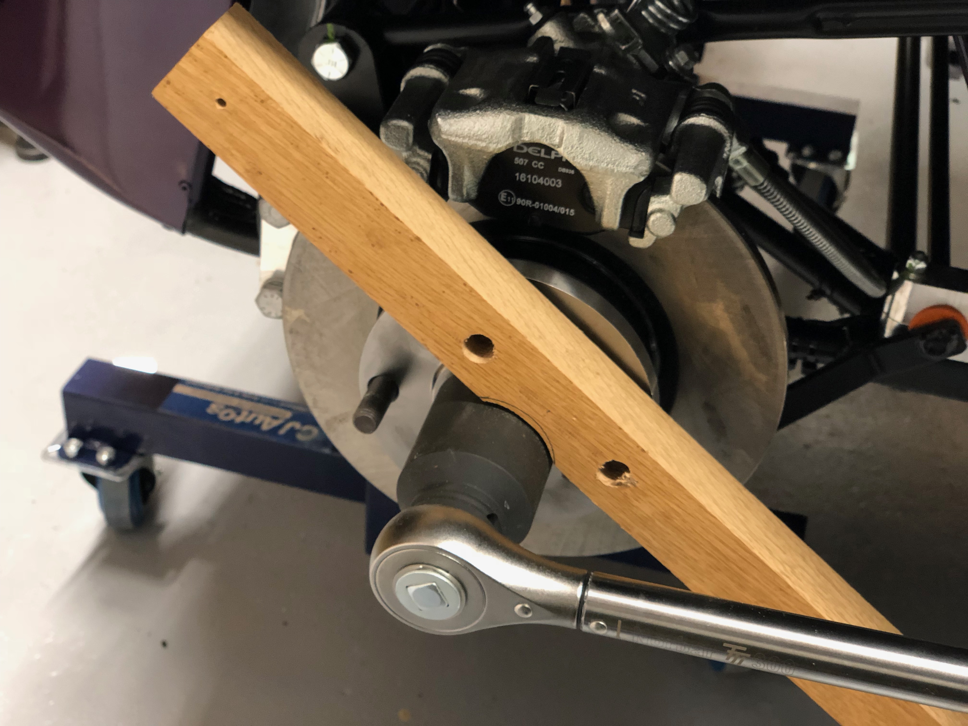
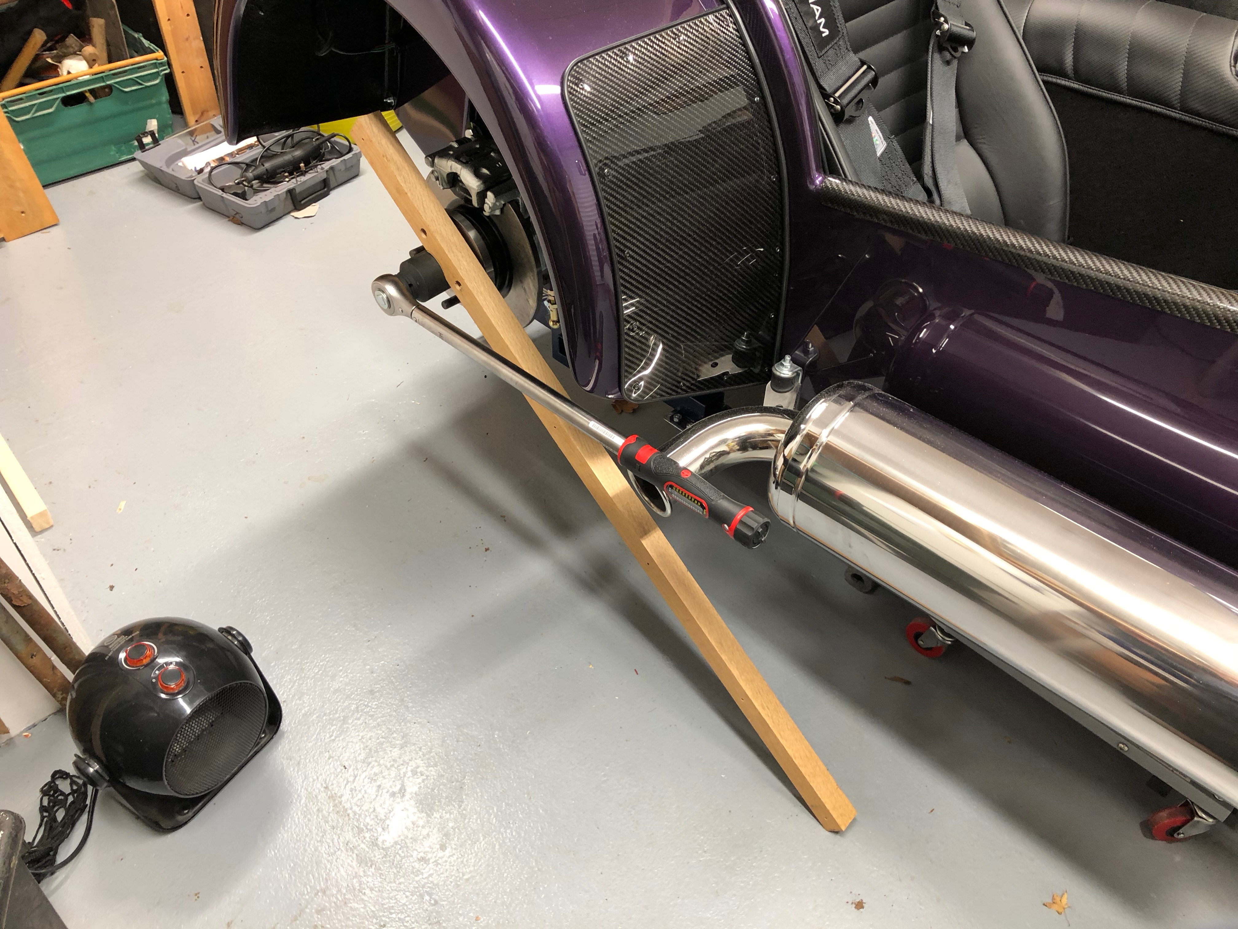
Anyway, back to the way I did things. I made a widget.
I took a piece of oak I had kicking about (it needs to be a hardwood or else I think you’ll snap something less sturdy) and fashioned a brace to stop the wheel from turning as I did up the hub nuts. Here’s some pictures…
Bonding the Front Wings – Finally
Last job of the day is to bond the Carbon Fibre Front Wings onto the Wing Stays. I’ve seen other blog posts where people go to great lengths to line up and level their wings. I was planning to be a lot more methodical than I finally was, but in the end I eyeballed them.
I added Sikaflex 521 to the top of the Sikaflex beads, that I’d applied a couple of days ago, and plonked the wings on top. I did some basic measurements to make sure they were level and centred but then left them to soak overnight. Here’s the best picture I could get of the Wing, Wing Stay and Sikaflex…
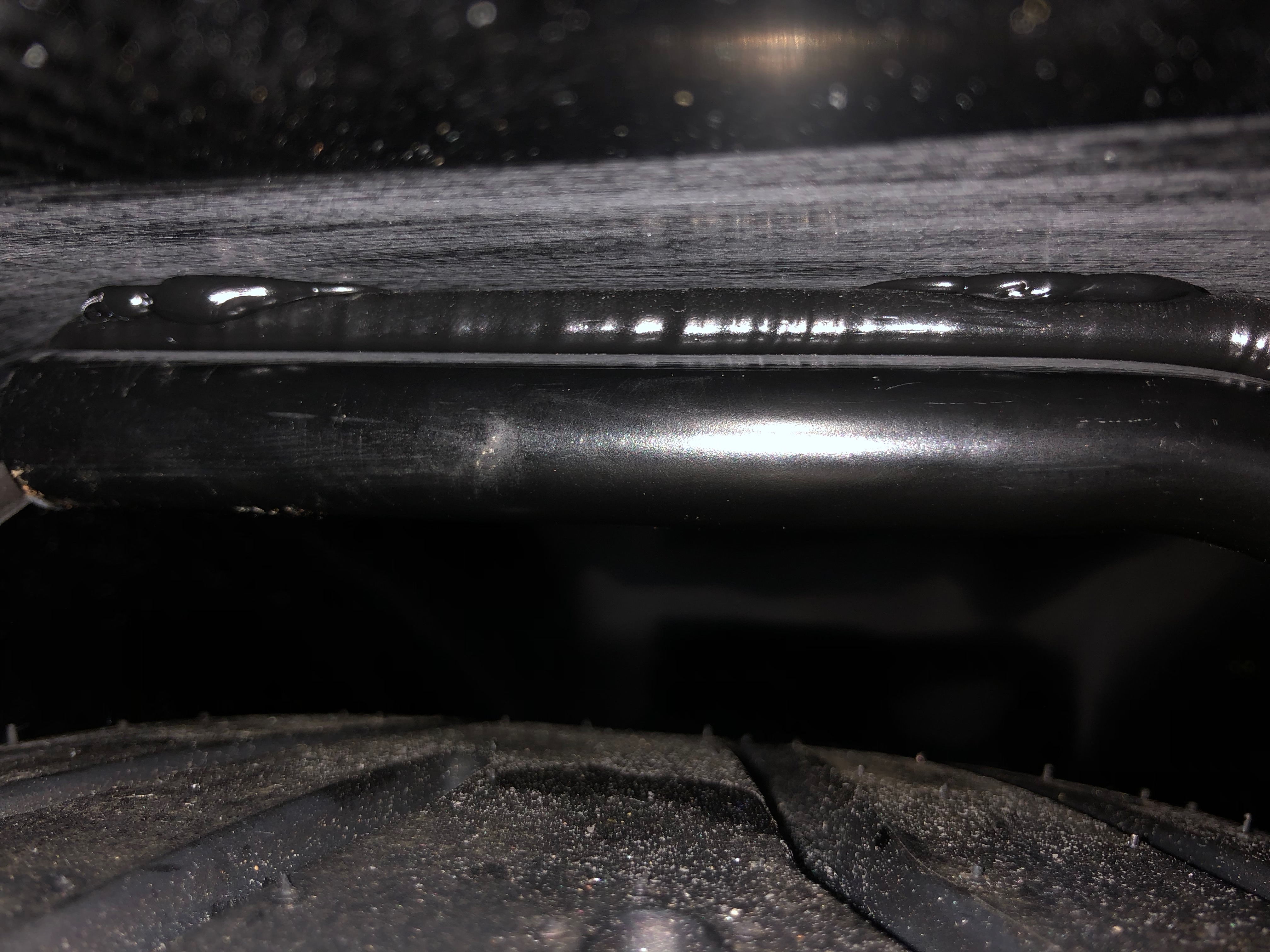
As you can see from the picture above, I sanded the Carbon Fibre to try and give the Sikaflex something to key against. The Sikaflex instructions didn’t seem to need that step but it wouldn’t hurt.
I had also got more nervous of the continual handling of the wings by this point and decided to coat them in masking tape – should have done something along those lines to the rear wings…

That’s it for today. Nearly 8 hours in the garage, more like 10 elapsed with meals and other jobs, and good progress I think.
Day 5 of the Big Push tomorrow…

Leave a Comment