

Day 3 of The Big Push – a Friday! I was hoping to get a lot done today but instead of a Big Push it turned into more of a Gentle Shove. Still… progress was made.
Today I wanted to get going on the spacing theory I’d formulated for the Front Wings and Wing Stays. There were also a bunch of tidy-up jobs that needed doing, not least of which was to get the routing of the handbrake cable finally nailed down.
Some Dates for the Diary
Before we get to any building though… I’d got enough confidence together to book both the PBC (Post Build Check) at Williams and the IVA (Individual Vehicle Approval) test. Today is November 24th, I’ve booked the PBC for next Wednesday, November 29th, and the IVA for the following Thursday, December 7th. That’s 5 days and 13 days, respectively, from today! Gulp! Better get a move on!
Front Wing Spacing
So, I’d decided that I needed to space the front wings off from the top of the wing stays. That would allow me to move the wings laterally, without hitting the vertical part of the wing stay, and therefore to get them centred left to right. It would also bring the wings upwards and give me more clearance from the tyres.
Now, the question is: what do I use as a spacer? Hmmm. I’m using Sikaflex 521 to bond the wings to the stays.
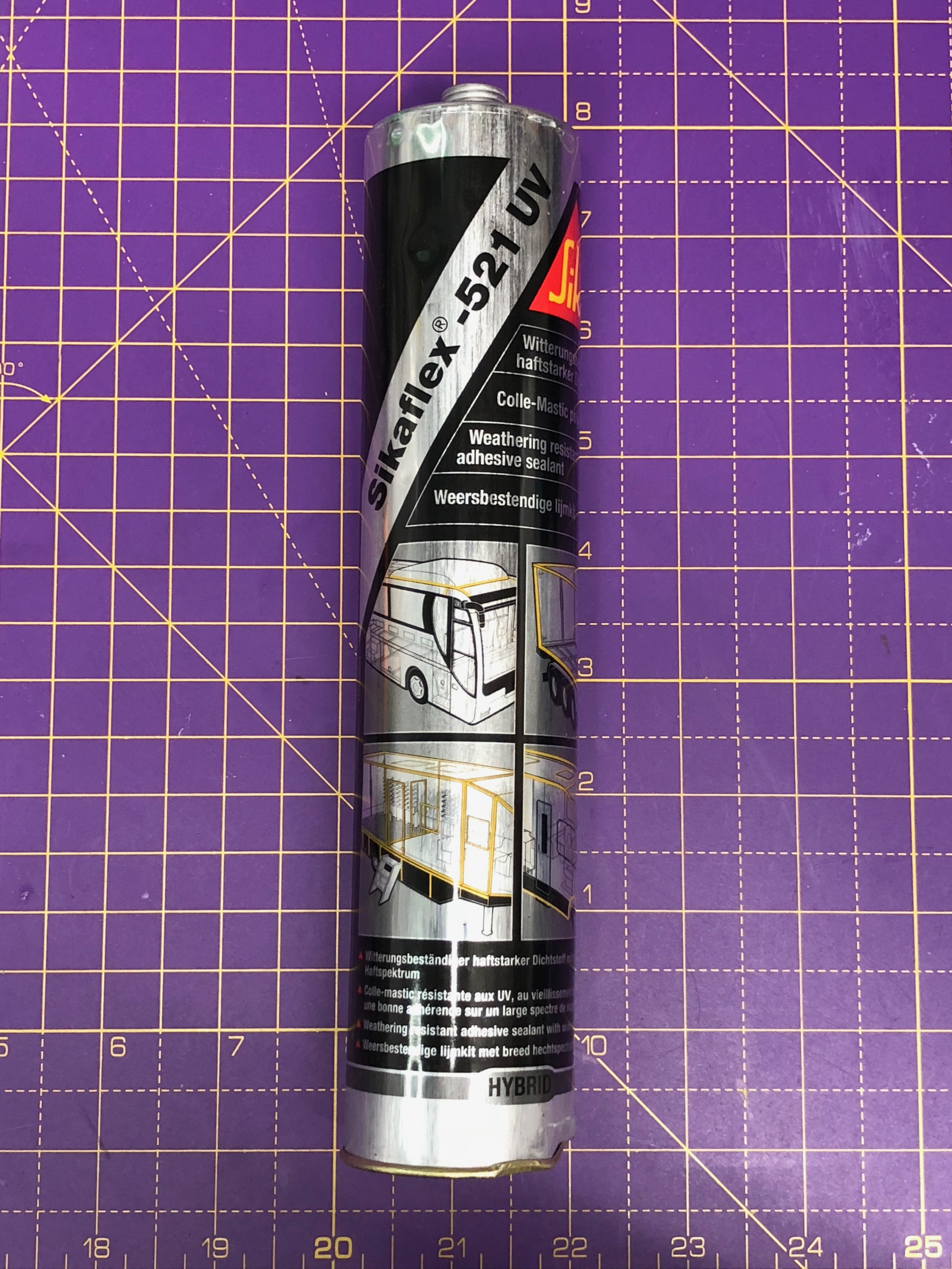
For my spacing needs I wasn’t really looking for anything to mechanically attach the wing to the stay – the Sikaflex will do that. All I needed for the moment was something to hold the wings in place while I cake the joint between the two with the Sikaflex. I also probably need to apply multiple layers of Sikaflex or else it will take an age to cure. It cures in the presence of moisture and needs about 24hours to set with a bead thickness of around 10mm and late November garage temperatures.
I thought about using some copper pipe that I have lying around. I could flatten the pipe and make it whatever depth I wanted. However, I wasn’t sure how the Sikaflex would react with the copper, probably inert, but didn’t want to risk it. I also didn’t know how it would work over time. I wasn’t thinking of putting the crushed pipe along the whole length of the wing stay, just a couple of pillars. But how would I attach the copper pipe to wing stay – Sikaflex I guess.
However, the obvious choice was to use a bead of Sikaflex along the wing stay, let it “go off” and then bond the wings to the stays with the first bead of Sikaflex as the spacer. I could be quite precise with the depth of Sikaflex I put down, so that gave me the control I was after. The only issue here is that I’m going to need to let the bead cure and that will add at least another day to this saga.
Anyway, decision made. So the first job today is to get that bead on and start it curing – I’ll have to be extra careful walking around the front of the car today with “wet” Sikaflex on the wing stays…

With four beads applied to the four wing stay arms I can move onto something else.
IVA Trim for the Carbon Fibre Wings
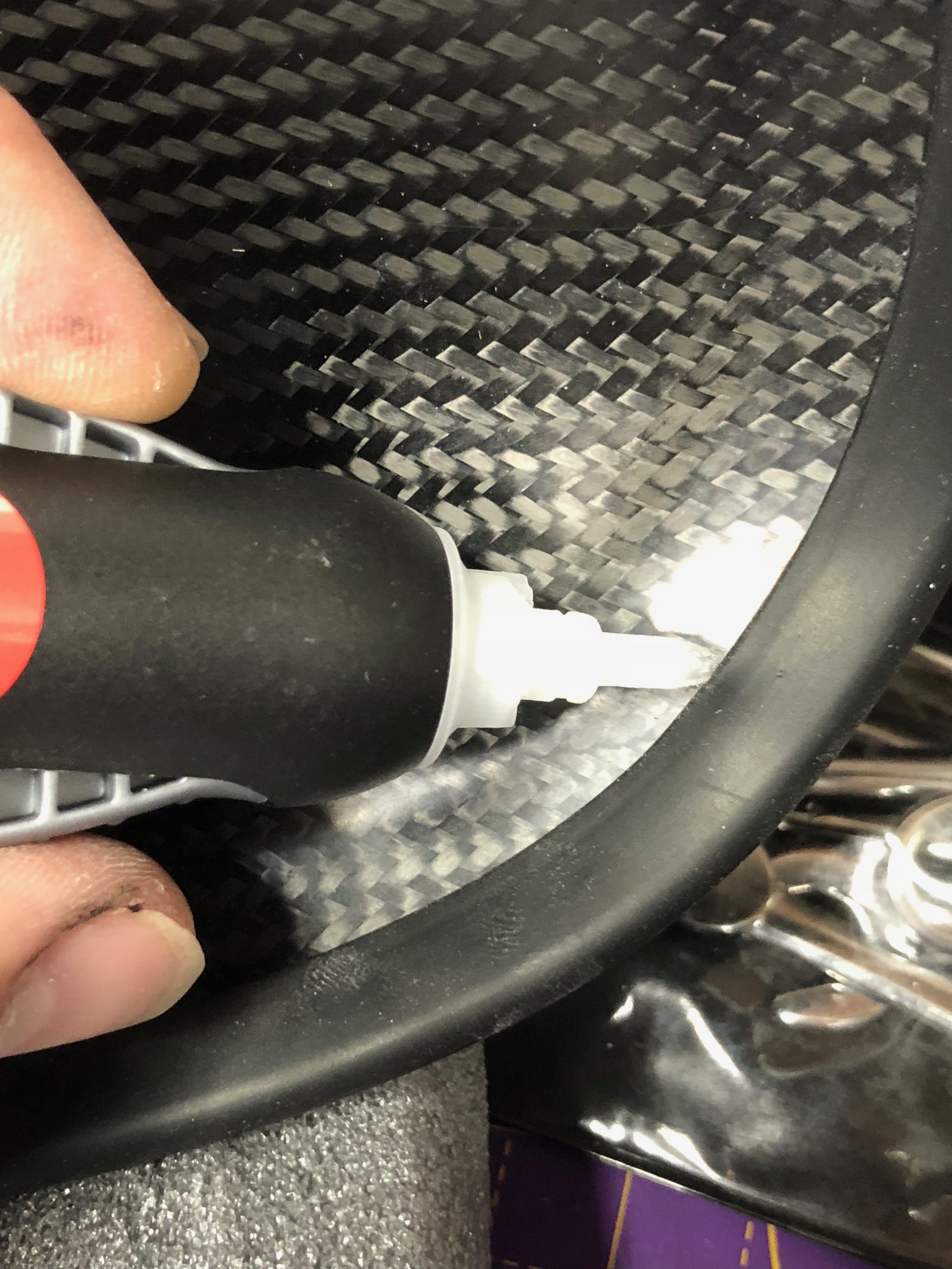
Next up is to get the IVA trim applied to the Carbon Fibre Wings. The trim needs to be permanently applied – I used Super-Glue/Krazy-Glue (Cyanoacrylate)…
Rear Brake Anti-Squeal Plates (I think)
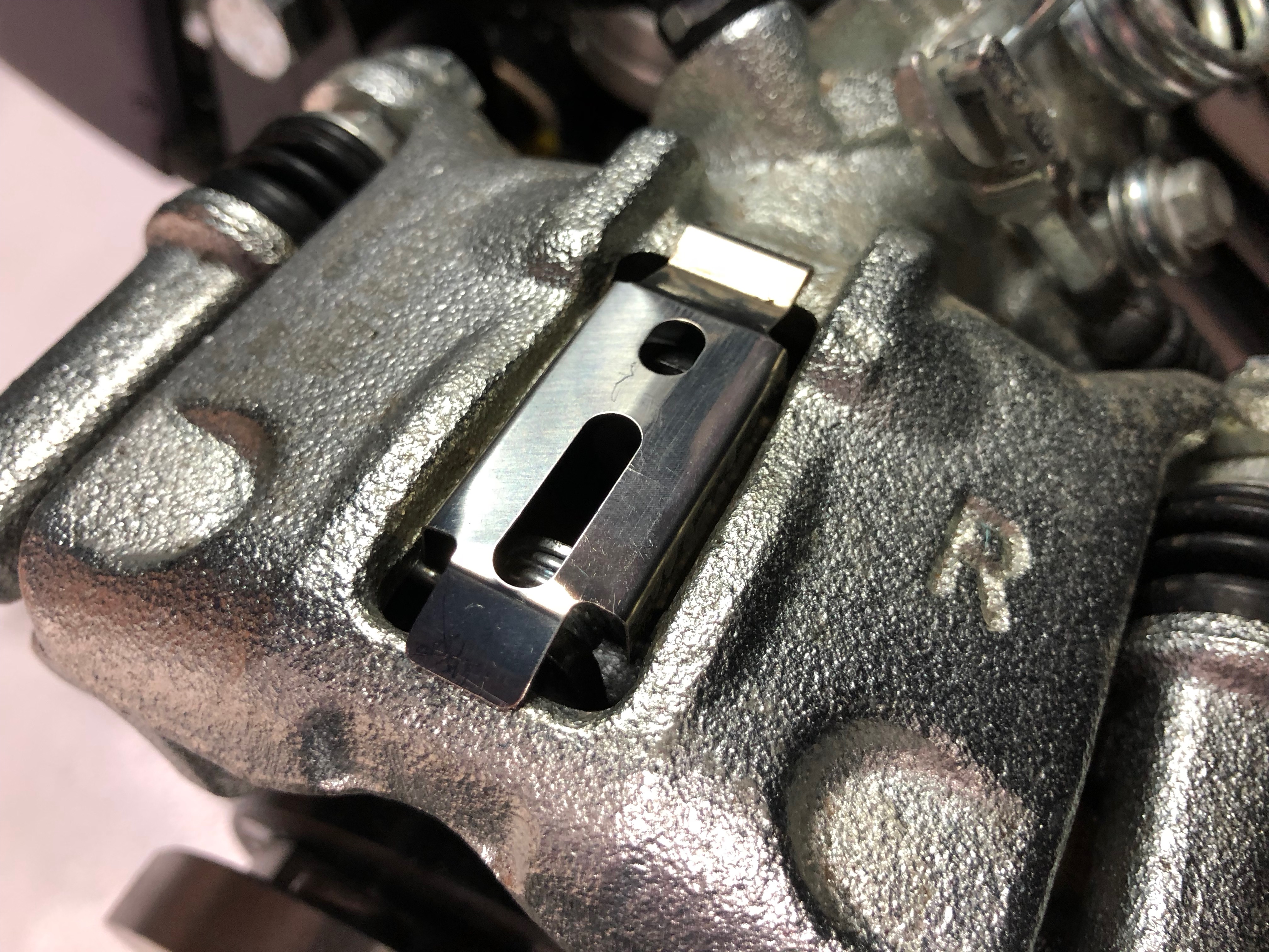
Simple job next to attach what I think are anti-squeal plates to the rear callipers…
Handbrake Cable Routing
Like so many other jobs, this one took longer than I was anticipating.
I’ve read many blogs where people have failed IVA because they’ve not got the handbrake cable “out of the way” enough from the drive-shafts. The cable has to loop over the top of the shafts, down behind, then under and up to the brake callipers. The cable essentially spirals around the drive-shafts on both sides.
I could get the RHS cable running reasonably nicely seeing as the handbrake adjuster bracket on the side of the diff allows the trajectory of the cable to start off nicely on its spiral journey.
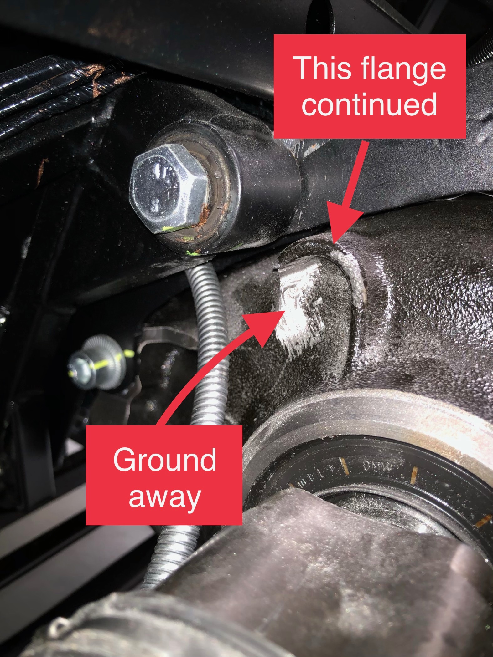
The LHS was proving to be more of a problem. As the LHS handbrake cable exits the transmission tunnel there’s a semi-circular flange on the diff casting that obstructs the cable’s exit. This flange tends to push the cable sideways and down… bringing it very close to the LHS drive shaft.
My solution… grind off the flange.
The flange didn’t seem to be used for anything and I just couldn’t see any need to keep the flange on the diff. So, out with the Dremel and I ground about 1/3 of the circular flange away…
… which allowed the cable to exit the transmission tunnel much higher than before the mod…

I used cable ties to keep the cable run away from the drive shaft.
After these changes the cable is kept on its spiral trajectory with two P-clips fixing it to the A-frame…

For those eagle eyed among you, you’ll note that the cable is actually P-clipped to the chassis in the picture above. It should be attached to the A-frame… that change will come later.
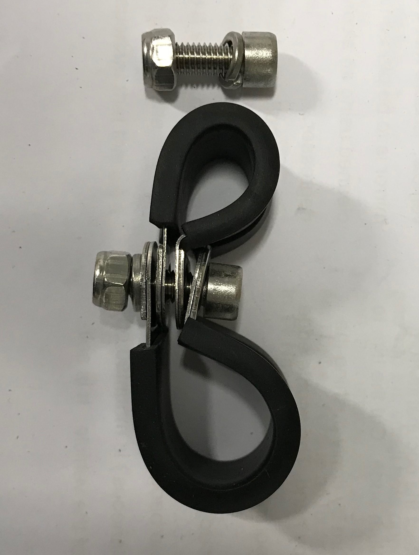
You can perhaps also see that I’d left on the long (3cm?) rubber cover/tube that come on the handbrake cable. This tube was really useful to place coincident with the P-Clip on to the handbrake cable, otherwise the P-clips I had would have been too big. In the end I think I used a 13mm and 19mm P-clip.
The P-clips were arranged like this…
The grinding of the diff took a lot longer than I was planning to spend on the handbrake cable today. But… I also got a much better solution than I had hoped for. This change worked really well for me. In all I probably spent two hours on the change. I used one of my Dremels but I needed the flexible extension attachment on the it or else there’d have been no hope of getting in there, it was tight. It needed access from both the top and bottom to get enough material off the diff and to get it to where I wanted.
Some Tidy-Up
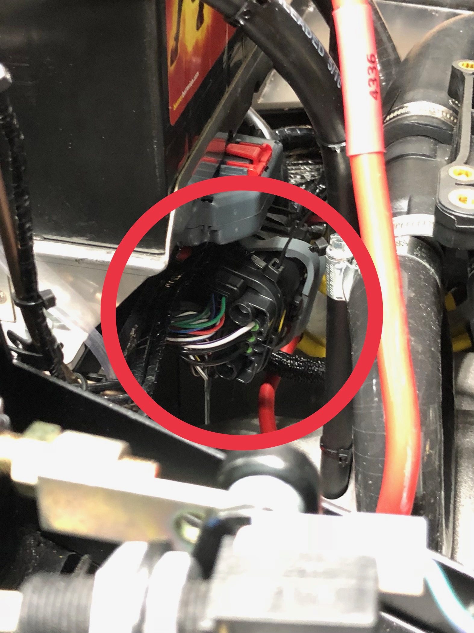
Before packing away for the day, I did a bit of engine bay tidy-up. I’d been pondering how the ECU plug was going to get fixed down for a few weeks now. When I finally got to having a look at it, rather than just thinking about it, it was straight forward. All the “spare” length in the cabling to the plug/socket all folded up on itself and I could cable tie it to the existing loom.
The final place for the ECU connector is circled red… under the battery in the picture below…
That was it for today, only managed about four and half hours today. Must do better tomorrow.
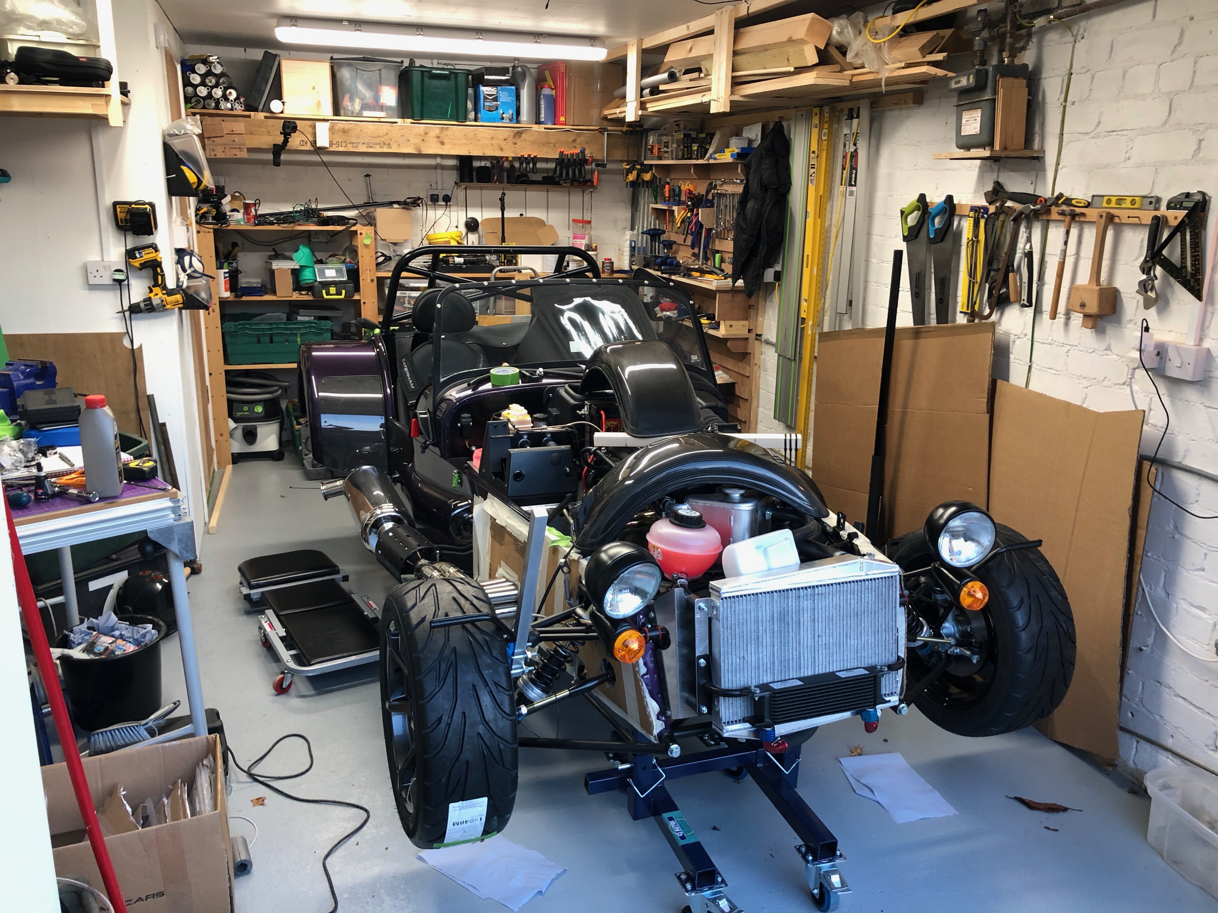
Here’s what the car looked like by the end of the day…

Leave a Comment