
Another Sunday and today is a half day on the car. I was hoping to get the rear suspension all fitted and hopefully even get the wheels on!
A-Frame
Not much to this one. It’s a bit of a faff if you’re on your own though… the A-frame didn’t want to sit anywhere sensibly for me as I tried to attach either the front or rear mounts. In the end I attached the rear mounts to the De Dion tube first.
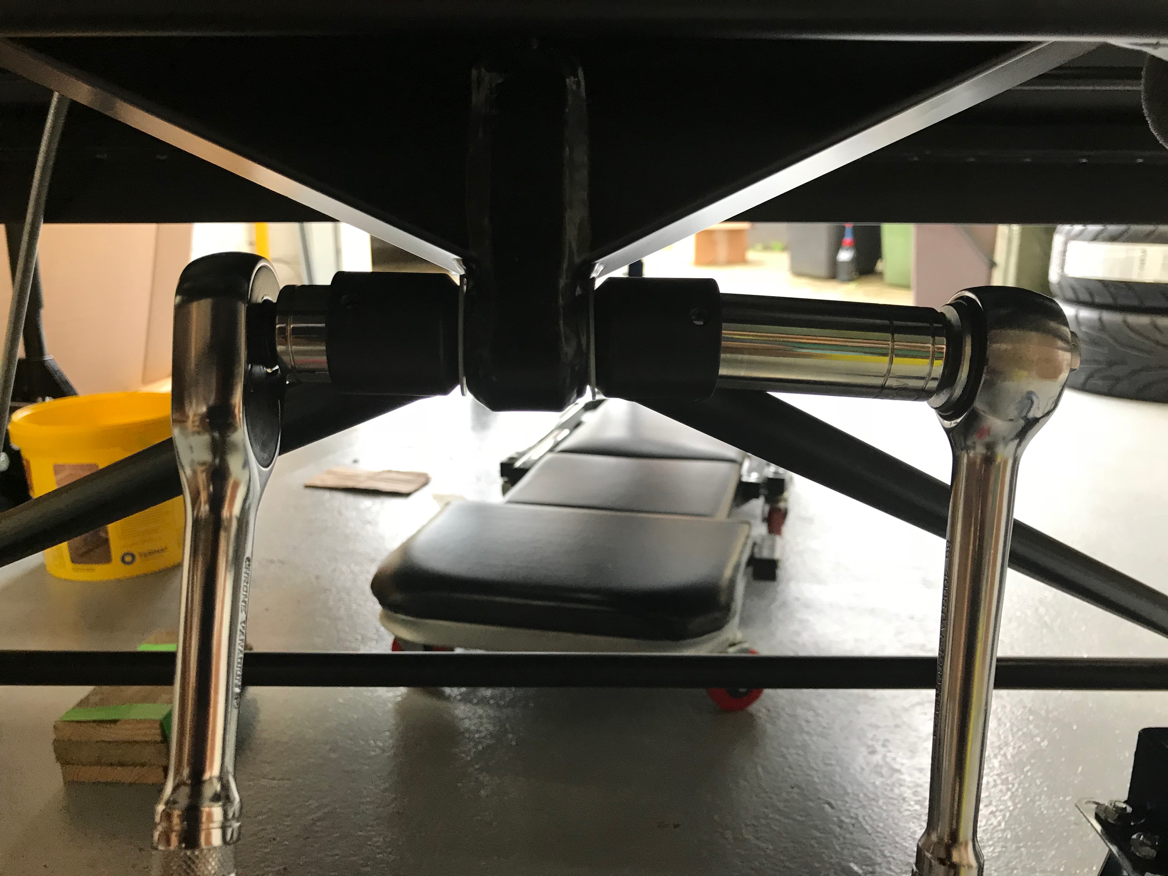
The A-frame fixes to the De Dion tube with an arrangement that has two tubes that surround the De Dion tube fixing point… one tube either side or the fixing point. At the bottom of each of these tubes is a recessed plate that bolts to the De Dion tube. Luckily I had enough sockets with long shafts and that were also narrow enough (I did have other sockets that didn’t fit) to fit down the tubes far enough to tighten up the bolt/nut. I also made sure I inserted the polythene washers supplied in the kit. The manual says to fit them if you have them… I had them so They got fitted!
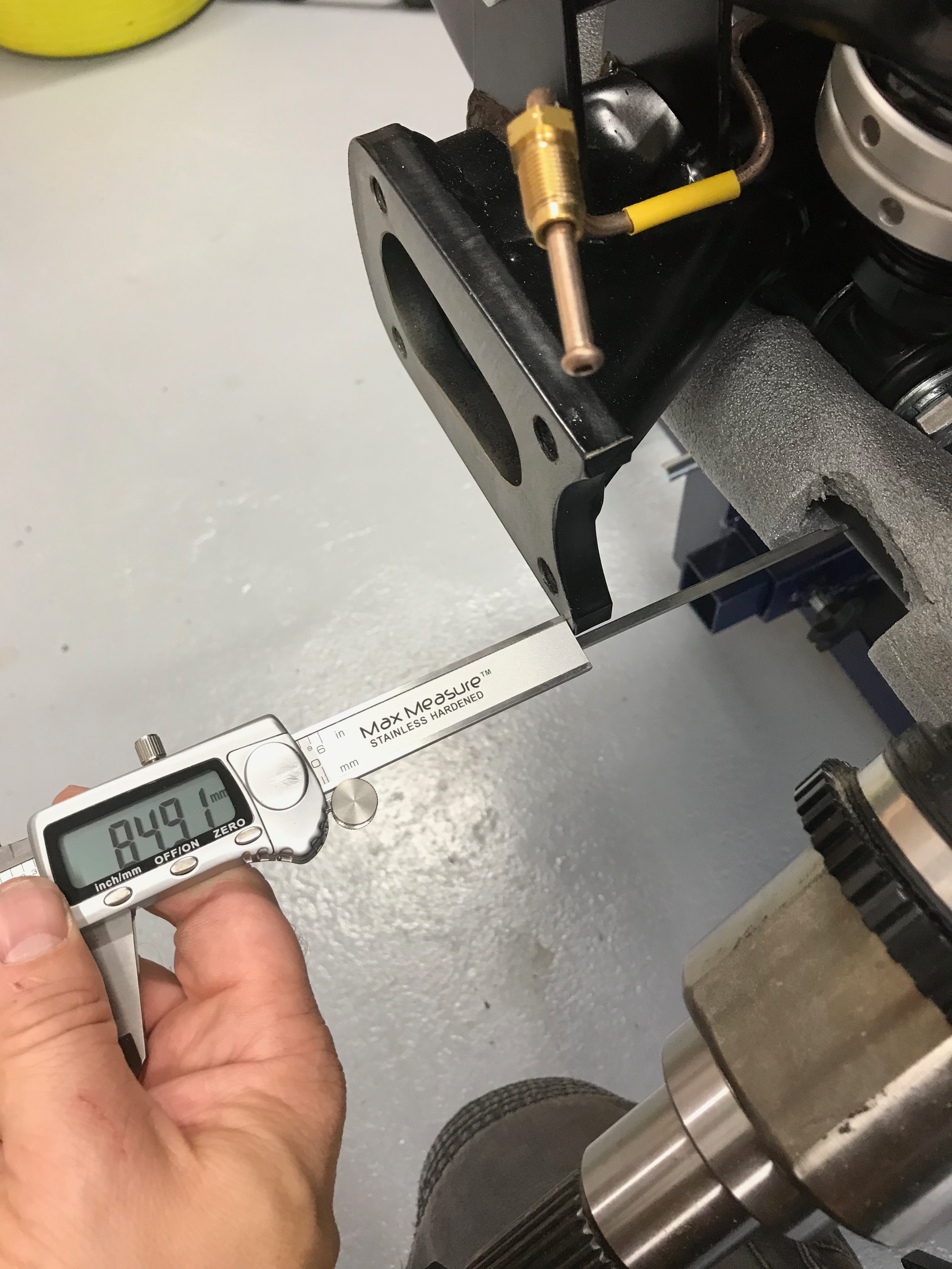
Once the rear was in place I could loosely attach the front of the A-frame and then start measuring. I centred the frame on the chassis with a digital calliper by measuring the gaps between the De Dion ear mounts and the chassis (see below). You can do this because shifting the a-frame left and right also moves the De Dion tube left and right… theyre attached to each other, right! That told me how many washers to add on each side. It was a simple job then to insert the correct number of washers and tighten everything up. And… of course check the A-frame was central after tightening. I also made a mental note to check the measurements once the car was supported on the De Dion tube (either directly or because it was sitting on its wheels) and not supported on the chassis as it is now.
Rear Suspension Ears
For all the racket (noise) that’s going to come from the rear suspension (and specifically the diff) it seems odd that the car is engineered to have hearing… well it certainly has ears, though some of my friends and colleagues will attest to the two not always being correlated!
The “ears” are two machined aluminium plates that locate the rear suspension and hold the drive shafts and braking in place. These “ears” bolt to the De Dion tube at their rear and then take the rear wheel bearings at the front. The rear callipers are then bolted outboard of the ears and then surround the discs which are in-turn are attached to the drive shafts. The ears are sort of a floating mounting point for all the rear suspension.
Attaching the ears is another simple step but needed a little finessing to get them on… As I mentioned in a previous post, it looked as though the drive shafts weren’t fully inserted into the diff at my first attempt. Once I offered up the ears it was obvious that the drive shafts were poking out of the chassis too far.
Out with the rubber persuader and the drive shafts were “knocked” home.
Attaching the ears is a simple job of repeating their installation as per the dry-fit of the the De Dion tube on the bench. You just have to take care not to rush the job thinking that you know what you’re doing.
Simples!
Rear Hubs, Wheel Bearings and Discs
It’s turning into a day of simple jobs…
I greased the inside of the wheel bearing and placed the hub, which holds the bearing, over the drive shafts. The bolts that hold the hub onto the ears pull the drive shaft partially into the bearing.
On the RHS you also have to attach the speedo sensor mounting bracket at this point.

The discs then slip over the drive shafts and are located with the castleated splines on the drive shafts. You then use the large nyloc drive shaft nut to pull the drive shafts fully into the bearing.
The 42mm nyloc drive shaft nuts need to be torqued up to 280Nm. That’ll be a job for when the handbrake is operational later on in the build – there wasn’t really any other practical way of me bracing the drive shafts against a 280Nm torque.
Rear Brake Callipers
The rear callipers then attach to the ears, remembering of course to put the brake pads into the callipers.
As the callipers go onto the car you also have to attach the drop links for the ARB.
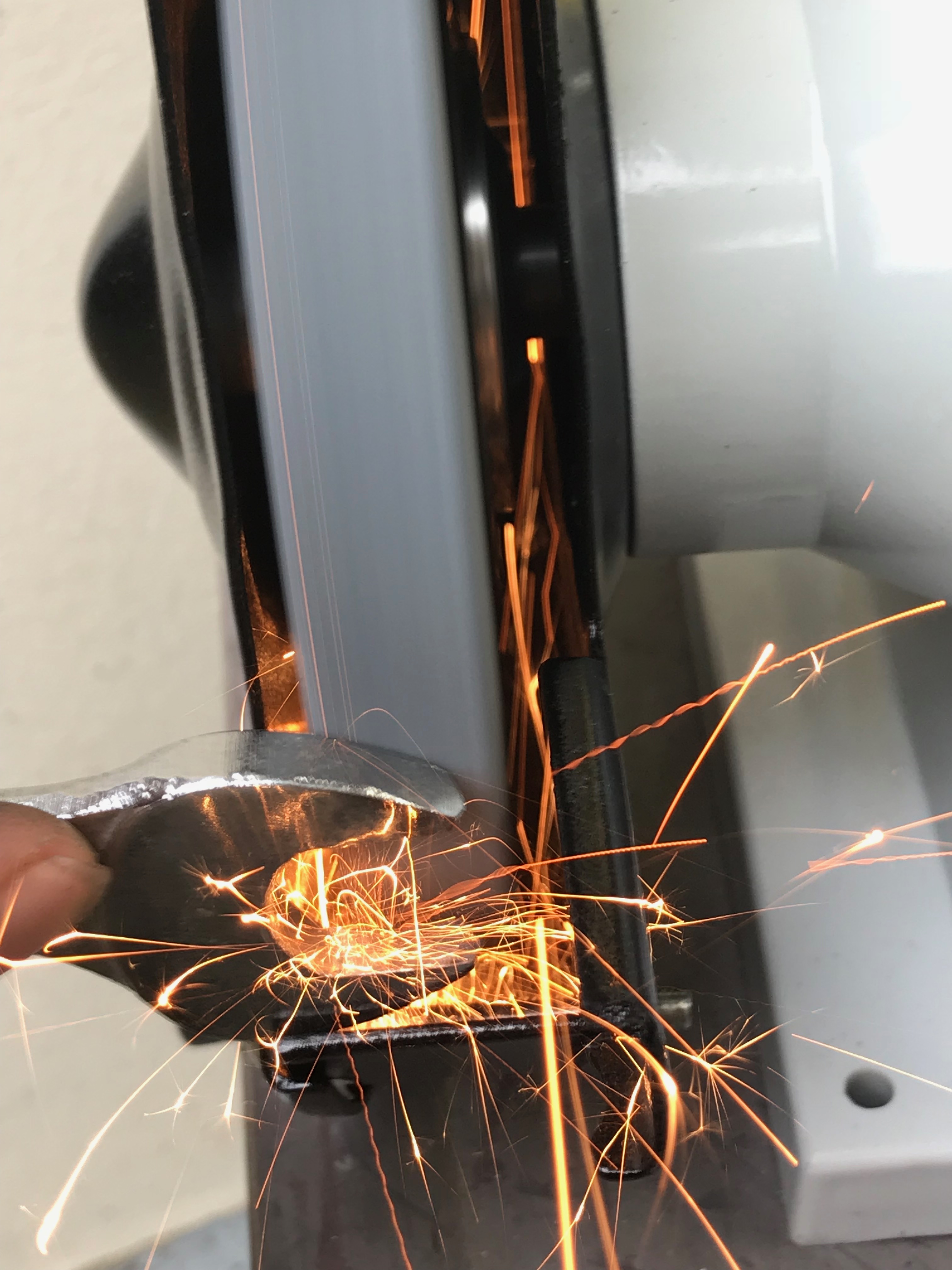
Getting the callipers on was a little tricky. There’s not a lot of room to get a 15mm spanner in to tighten up the bolts at the back of the ears. I ended up having to grind down a spanner to fit.
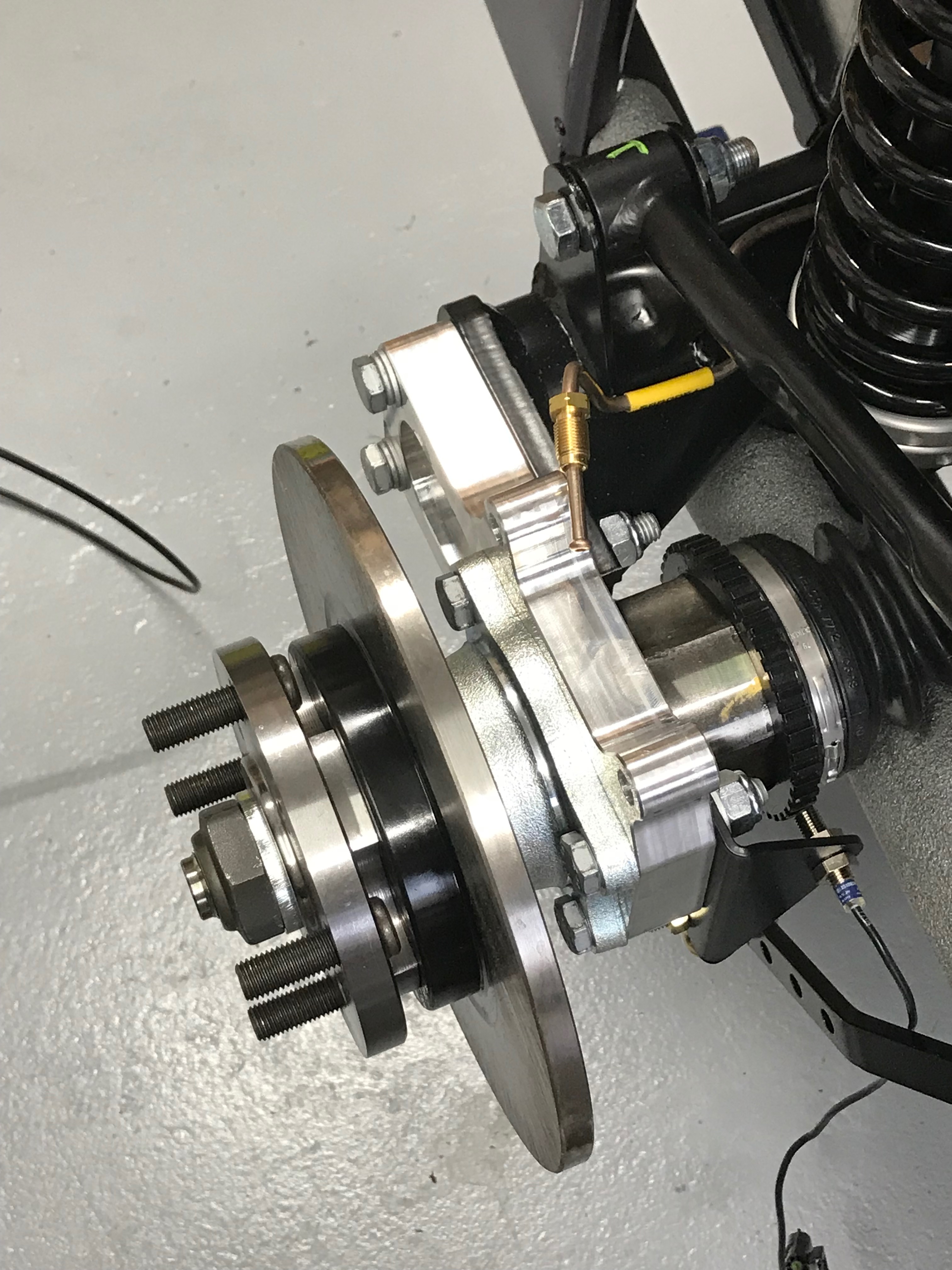
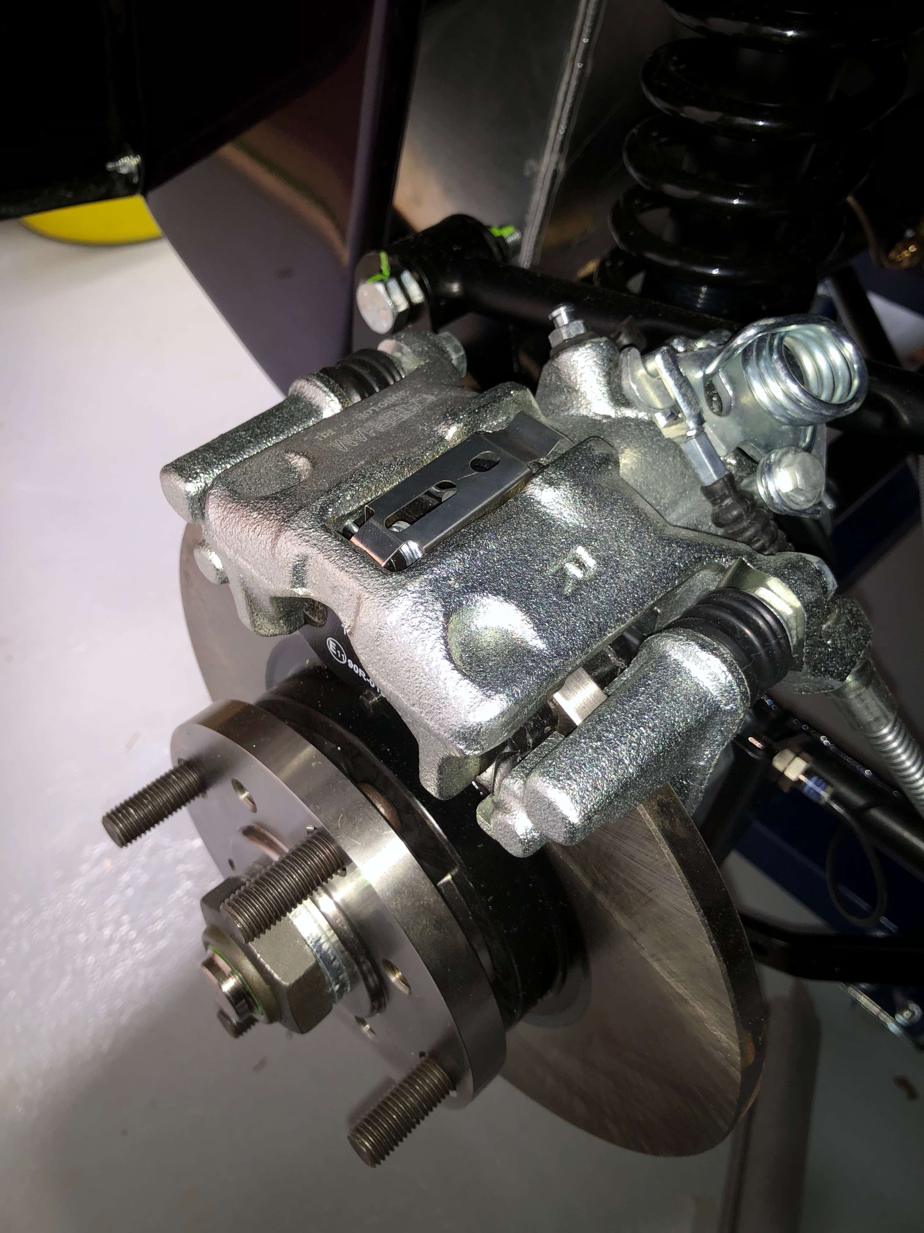
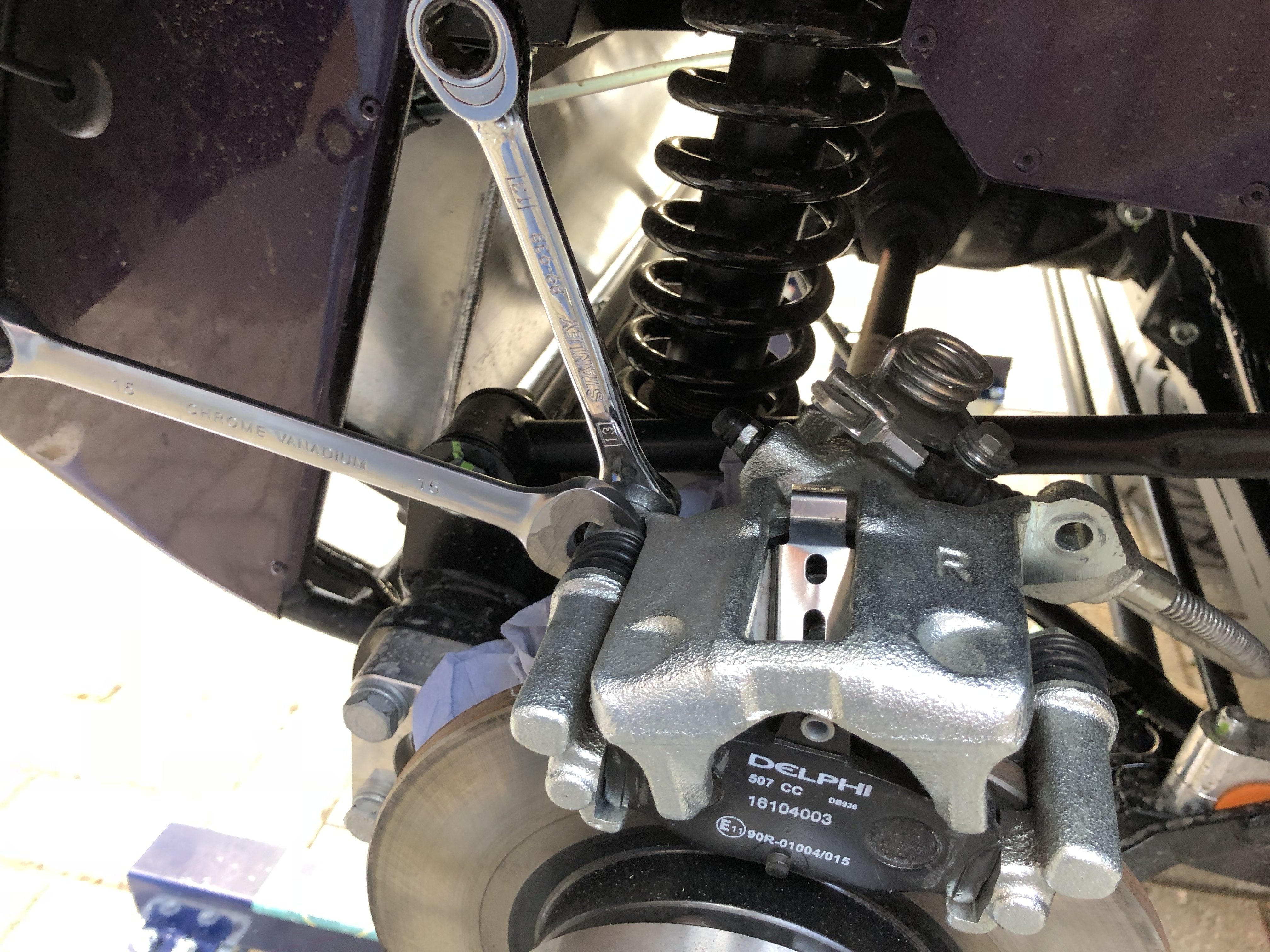
The rear hub and brake assembly now looks like this…
And another one…
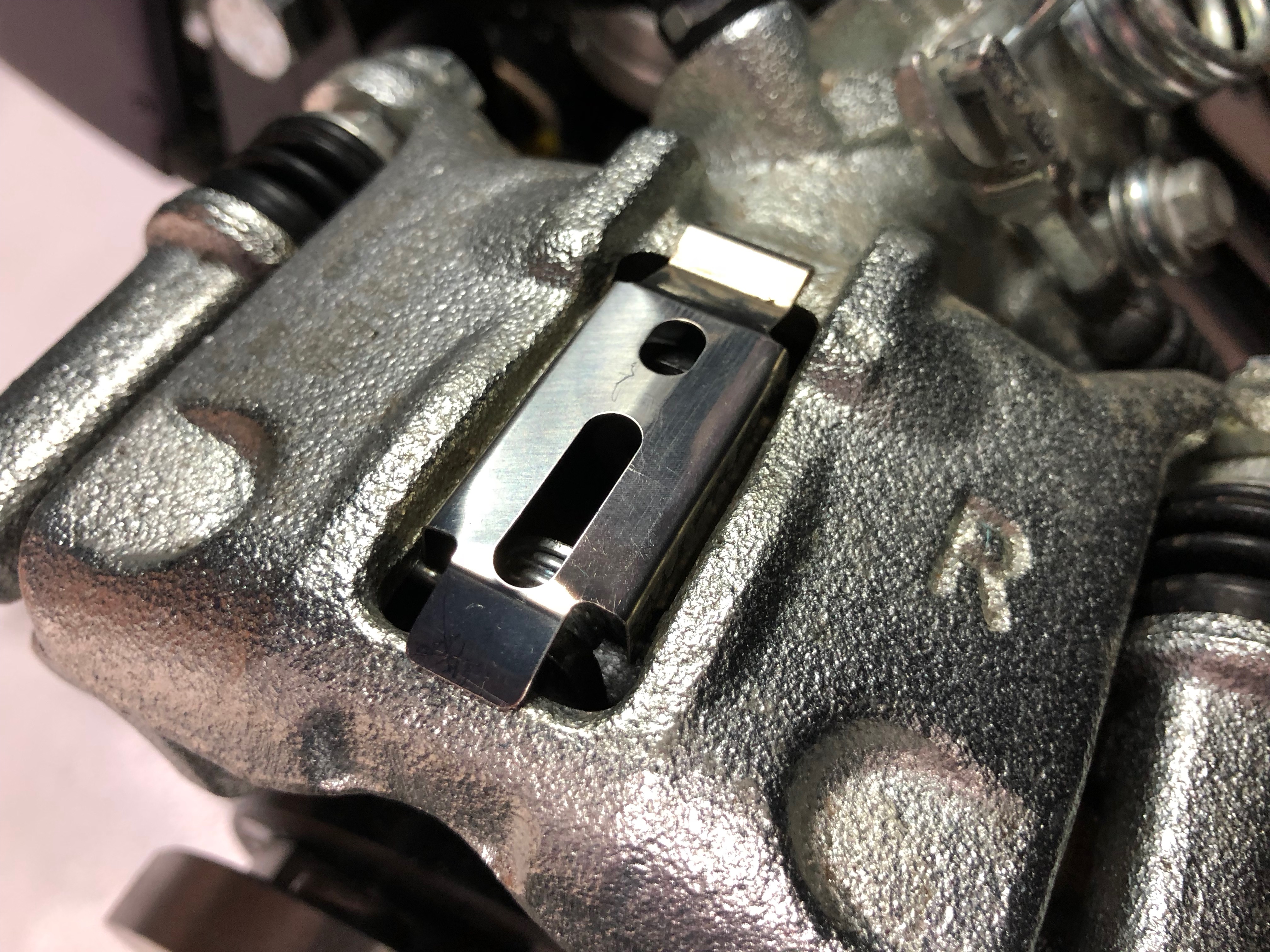
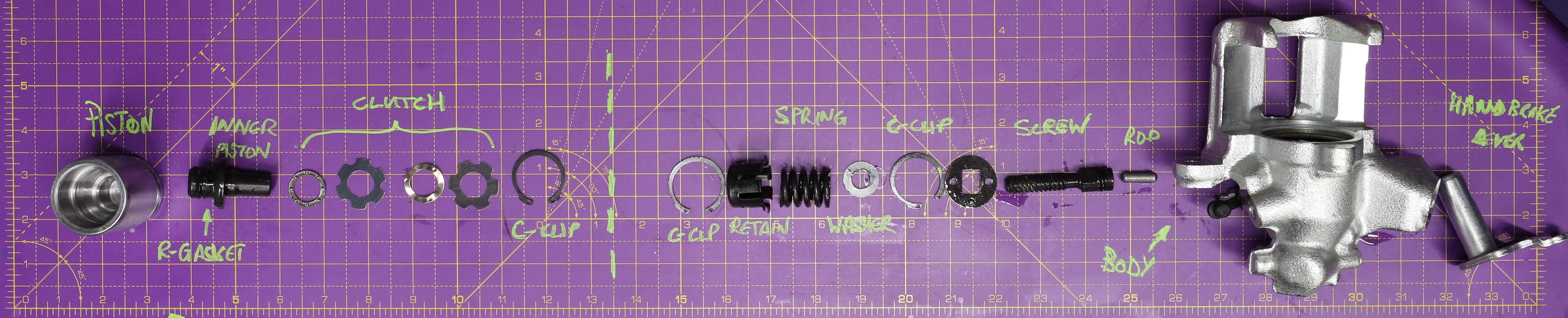
If you’re the type of person that just can’t help but take things apart then you’ll appreciate the need that drove this next image. It’s the innards of a rear calliper. I hope to do a post at some point about how this works and why you have to rewind pistons and the like.
It’s Wheely Good
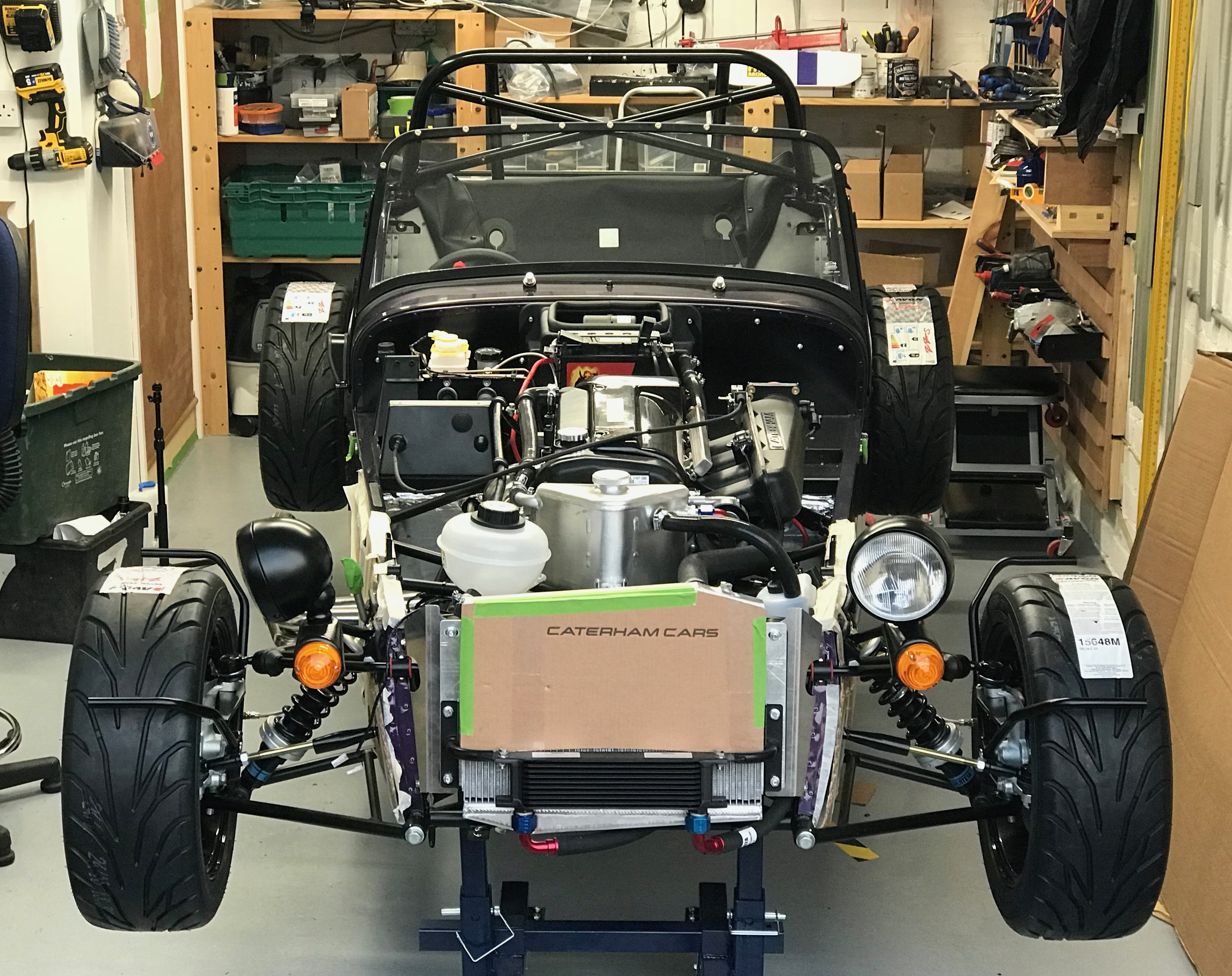
We’re really getting there now. Front and rear suspension on… time for the wheels!

End of another good day… great progress now and thinking I should be looking to start the car soon.

Leave a Comment