
This is a post from the future and a rather technical one at that – so stop reading now if that’s a big turn off for you 🙂 Having got the engine running I thought it would be a useful addition to the blog to have a diagram of the engine water and oil plumbing. The plumbing’s not that difficult in the end but I struggled to get the whole thing in my head from the build manual.
But what sort of diagram? I’ve seen people blog a sort of “schematic” view of the pipework – somewhere between a cross section of the engine bay and a components/pipework view. And while that’s great I thought I wanted something, hopefully, even easier to understand. I also thought there’s two ways of looking at this – the very literal, physical way of looking at it (perhaps 3D) and then the very abstract, theoretical way of looking at it (a schematic). So, I thought I’d do both…
Please let me know if I’ve got anything wrong in this post… I’ll be very happy to correct any mistakes or misunderstandings on my part.
Animated 3D Model of Water and Oil
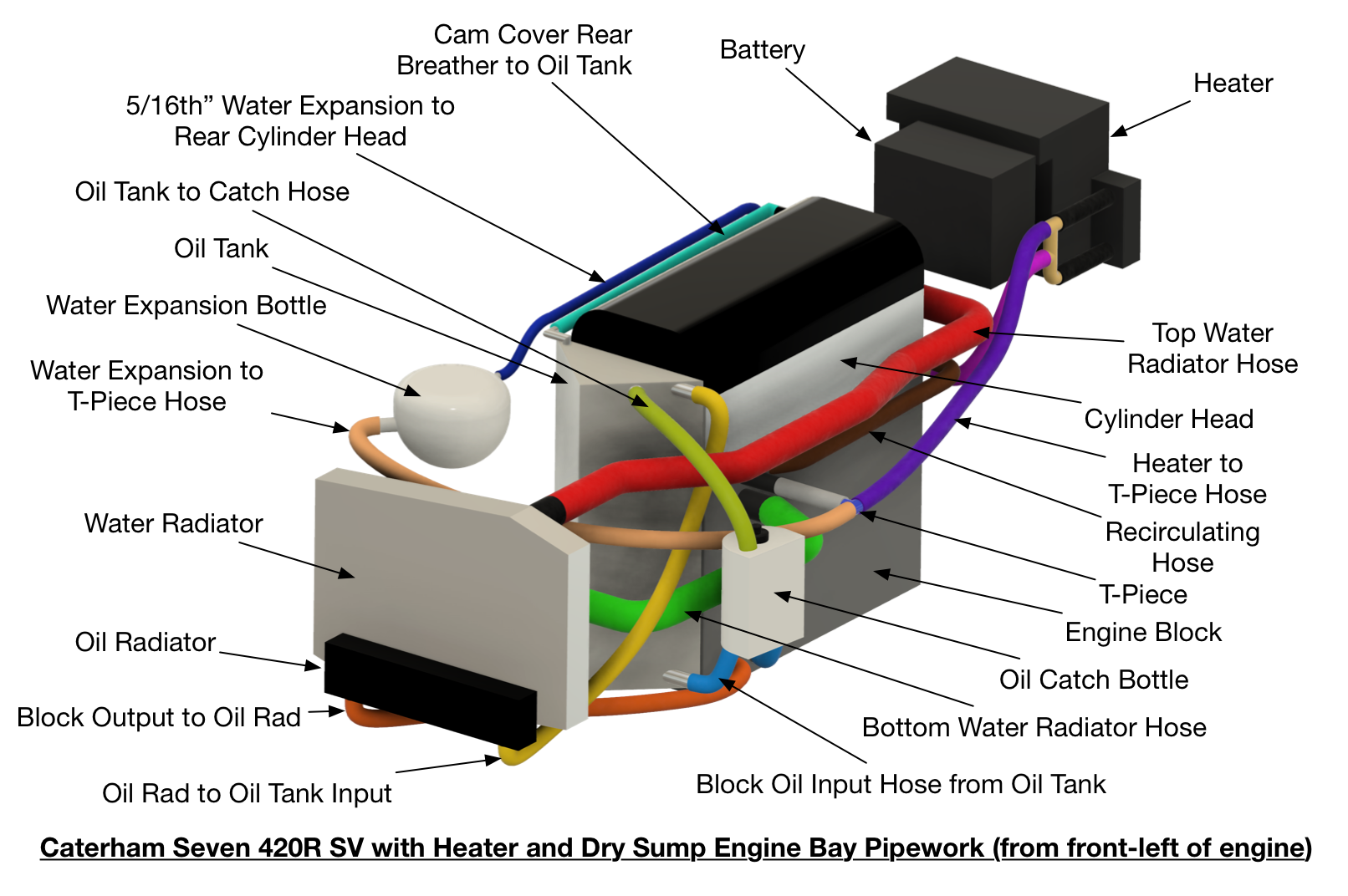
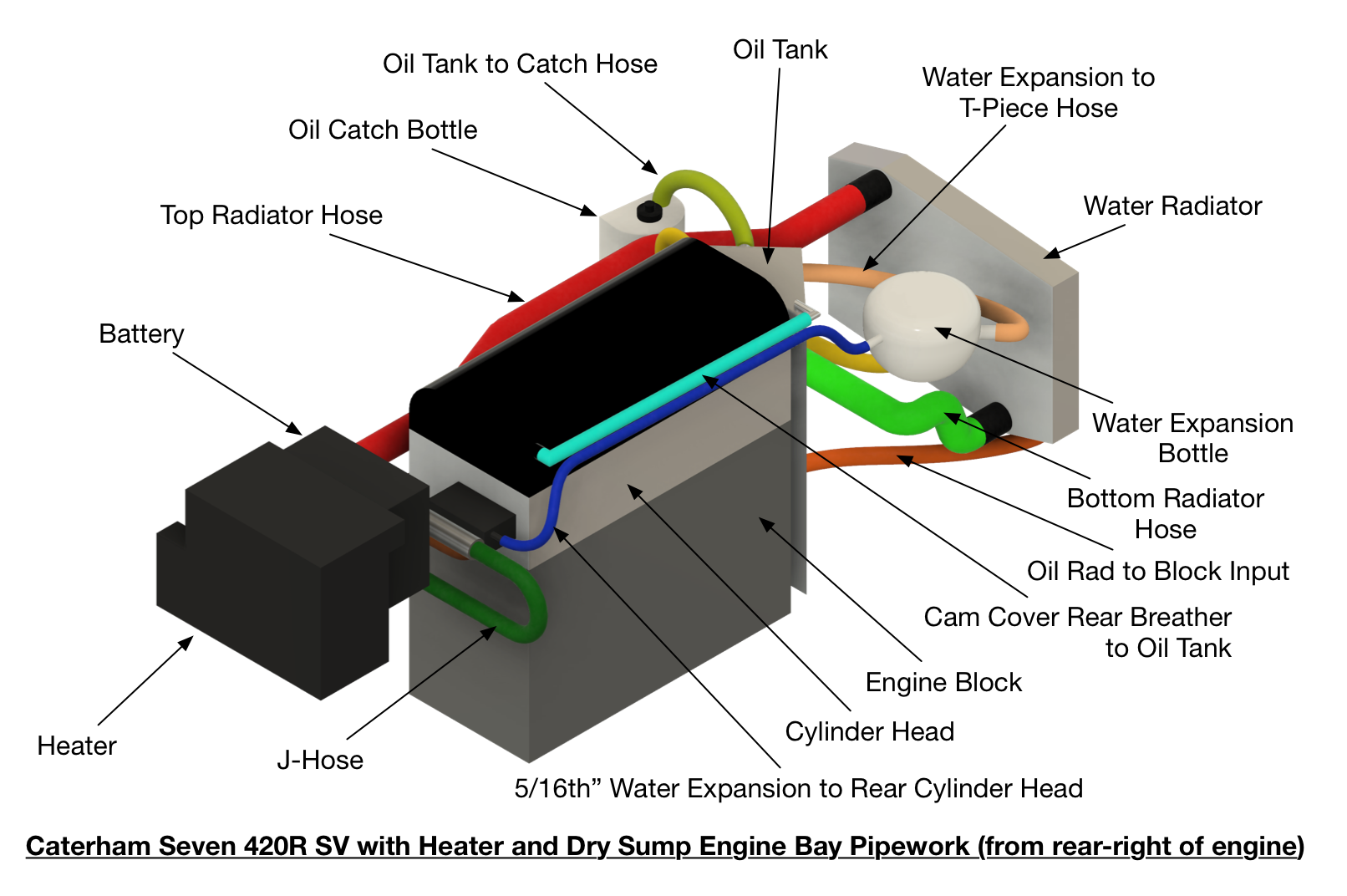
So… here’s an animated 3D CAD model of how the plumbing on our 420R SV, with Heater and dry-sump, ended up. There may be more optimal pipe routing, but this is where we got to. You should be able to click the video to enlarge it on whatever device you’re using.
… and here’s a couple of labeled diagrams to help with the animation…

The Water Circuit Schematic
There are essentially four parallel paths to the water circuit on our car, all are in parallel with each other but have different diameter hoses and therefore different flow rates:
- Recirculating Loop
- Heater water loop
- The Expansion Loop
- Water Radiator loop
Because I’m an electronics guy, I like to think of water circuits like electrical circuits, so here’s the way I like to think of this car’s water flow (the wider the pipe in the diagram, the greater the flow – there are all sorts of other factors that go into flow rates so I’m not going to try and quantify that statement, there is a lot of material on the web about laminar and turbulent water flow through pipes and all the factors that go into that):
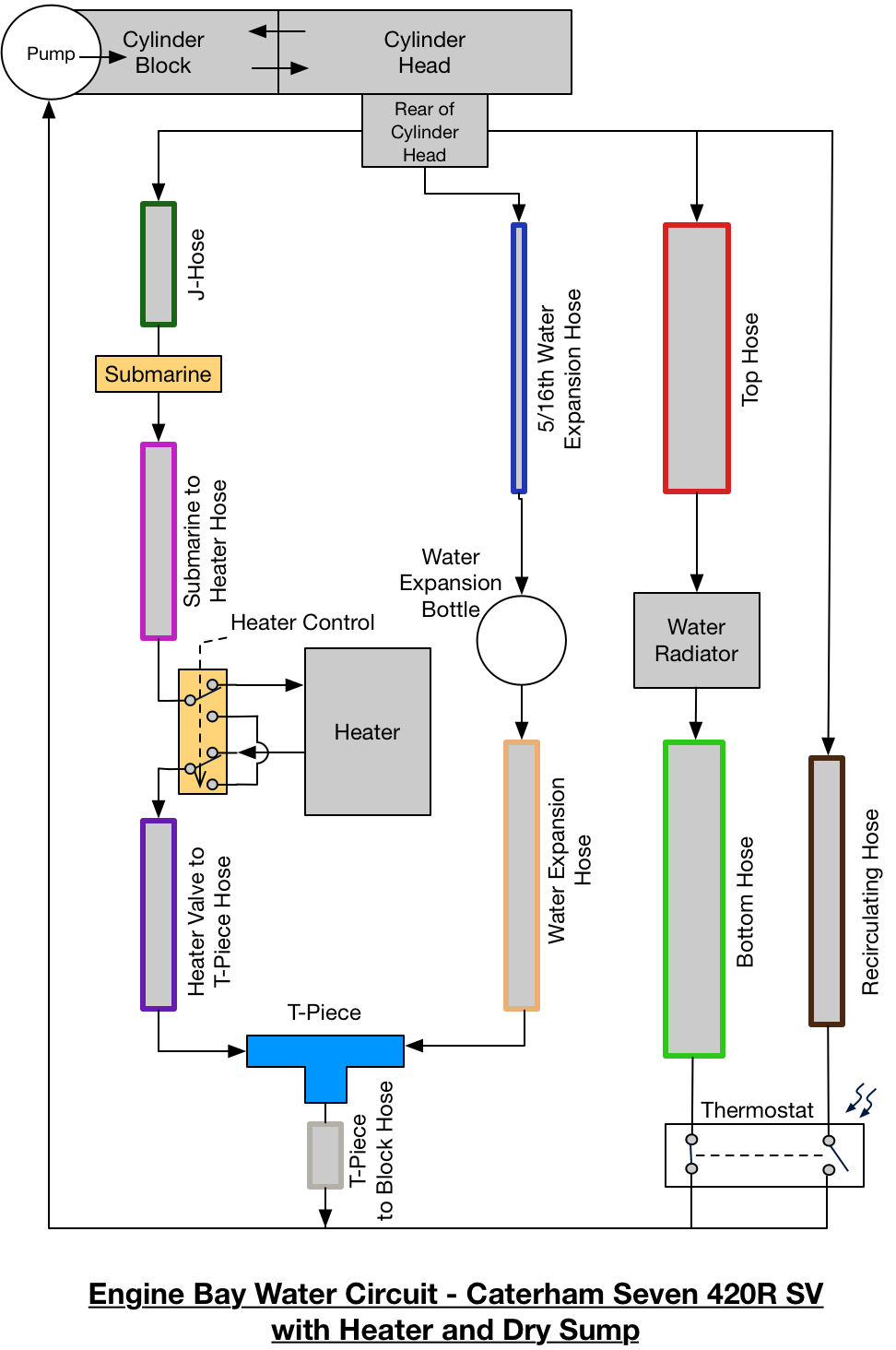
Now lets look at each of the four parallel water paths…
Water Heater Loop
The water heater loop runs from the back of the cylinder head to the thermostat via the J-hose, then the temperature sensor (submarine), the heater (optionally included using the heater control valve) and finally the t-piece.
When the driver operates the Bowden cable to open the heater valve, water flows through the heater element. When the heater valve is closed the heater is bypassed.
Water Expansion Loop
The water expansion loop is in parallel with all the other loops and connects the back of the cylinder head with the thermostat through the 5/16th” hose, the expansion bottle and the t-piece. There is limited “flow” of water in this loop because of the reduced diameter of the 5/16th” hose. This loop is used to provide a compressible air gap in the expansion bottle for hot water to expand into.
The cap on the water expansion bottle also provides a safety valve in case the water in the engine gets too hot and the cap will vent and relieve the pressure in the system to prevent, for instance, a gasket or hose bursting with excess pressure – not a good situation to be in!
Recirculating Loop
To help getting the engine up to temperature faster and to better regulate engine temperature the Duratec engine has a short hose connecting the back of the cylinder head to the water pump, through the thermostat assembly.
I’ll talk some more about the thermostat later but the thermostat is arranged so that water either flows through the recirculating loop or the radiator loop – the thermostat switches between the two. Water flows in the recirculating loop when the thermostat is below its operating temperature and in the water radiator loop when above its operating temperature. This isn’t a binary thing though… It takes a range of something like 10-15C for the thermostat to fully activate. During this temperature range both the recirculating loop and the radiator loop are passing coolant – at varying flow rates dependant upon how “open” the thermostat is.
Water Radiator Loop
Again, this loop is in parallel with the other three loops but is switched into the circuit once the engine block temperature reaches the thermostat’s opening temperature. Once the thermostat reaches this temperature it’s valve opens and water is allowed to flow through the water radiator. The construction of the thermostat and how its placed in the block effectively switches coolant flow from the recirculating loop (at low engine temperatures) to the radiator loop (at high engine temperatures).
Even after the thermostat has “opened” the radiator loop (and “closed” the recirculating loop) water will carry on flowing in the heater loop and the expansion loop. It’s not obvious to me how the relative flow rates change when this happens… the recirculating loop pipe is short and narrow in comparison to the top and bottom radiator hose which are long and wide. Flow rate is a complex calculation and ISTM that the recirculating loop and radiator loop probably have similar flow rates – therefore not affecting the other two loops when the thermostat is open or closed… but that’s just a hunch (if anyone can suggest a way of proving or disproving that hunch then I’d love to hear from you).
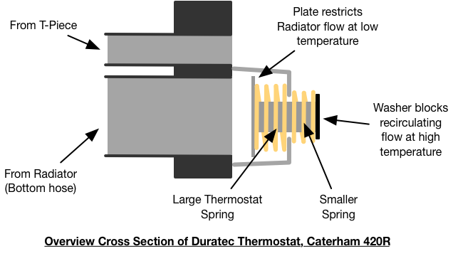
What’s the Thermostat Assembly About Then?
The thermostat assembly on a Duratec engine is essentially a wax operated valve. A pellet of wax operates a valve with two springs working in oposition to the wax. When the wax melts is expands and moves an armature to an open, high temperature position, where the radiator loop is opened and closes the recirculating loop. The springs then move the armature back to it’s low temperature position when the coolant temperature drops and the wax contracts when it solidifies.
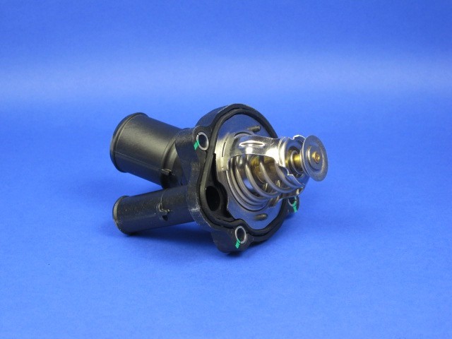
There are essentially three water inputs and one output on the thermostat housing assembly as follows:
- Heater and expansion input – this input takes coolant from the t-piece and which is always flowing. It’s the smaller pipe on the outside of the thermostat housing (the pipe on the bottom left of the picture above)
- Recirculating input – this one’s a bit odd. There’s a pipe feeding into the cavity behind thermostat housing but which is not part of the assembly shown in the picture above. This pipe is part of the cylinder block. The flow from this pipe is either allowed or disallowed by the operation of the thermostat. When the thermostat is in the high temperature position the flow of coolant from the recirculating pipe is closed. When the thermostat is in the low temperature position, recirculating flow happens.
- Radiator Loop input – this input to the thermostat comes from the larger of the two pipes on the outside of the thermostat housing. When the thermostat is in it’s high temperature position, coolant is allowed to flow through the radiator into the thermostat cavity and then on into the block and head.
- Thermostat output – while there looks to be no output from this assembly, when it’s installed in the block a cavity is formed between the thermostat housing and the inside of the block. This cavity, leading to the rest of the engine, essentially creates an output from the thermostat assembly.
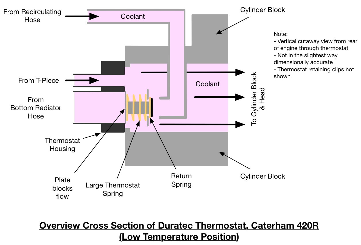
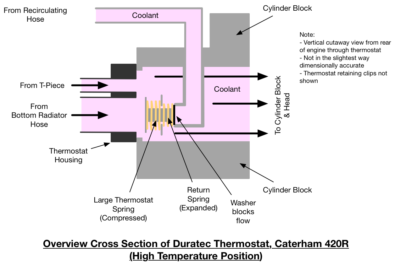
Below are two diagrams, one showing the arrangement of the thermostat in it’s low temperature position and one diagram showing the arrangement in it’s high temperature position. It takes 10 to 15 degrees C for the thermostat to move between the two states.
Here’s a diagram of the thermostat in cross section (side view) on its own:
Now lets add the thermostat and housing into the cylinder block and see what happens at low then high temperatures.
Cylinder Head Temperature vs Submarine Temperature
TBD
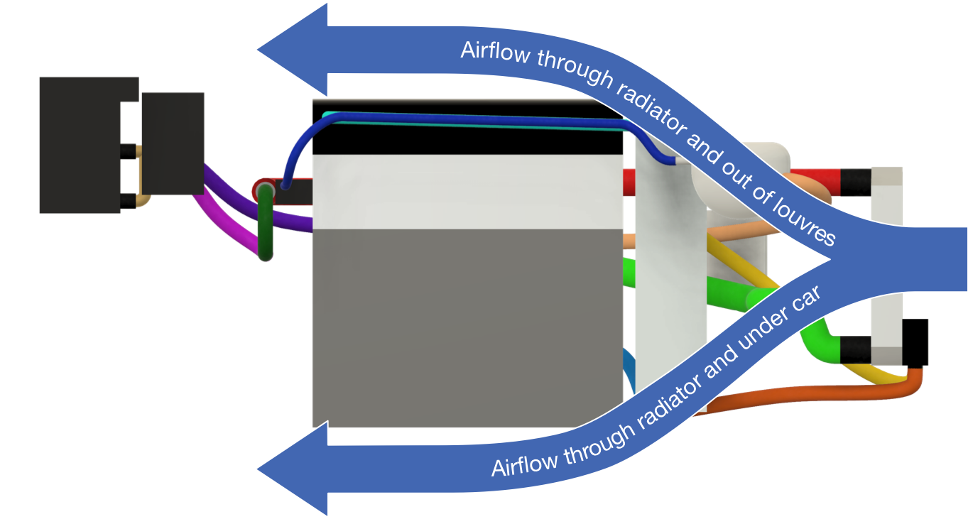
What’s the Fan for?
At even higher temperatures than the thermostat operating temperature, the water radiator fan turns on to provide cooling. The fan is only needed when the car is stationary or in slow traffic – because a moving car will have more cooling provided by airflow through the front nose-cone grill than the fan can deliver…. there’s a lot of air flow with a car travelling at say 20mph, try that speed on a bicycle to test the difference between that speed and what the water radiator fan can do.
I’m no aerodynamicist but it seems clear that as the car is moving forwards air passes through the radiator and then out from the engine bay from under the car or through the bonnet louvres. There is of course some sort of “wing effect” going on and it wouldn’t be surprising to find there’s positive upwards pressure under the engine bay and so the louvres are more effective than might otherwise be thought. It will be interesting to put pressure sensors on a car and see what they can tell us about these air flows.
In order to calculate how effective the fan is we can do some arm-waving…
… in rough terms…
The fan on a Caterham generates an airflow of around 1360m3/h (when the car is stationary – from the SPAL website), or 0.3778m3/s.
Now, the frontal cross section of a Seven 420R radiator is approx 430mmx195mm (I’ve removed any area associated with the oil radiator which I’ll discuss later). This works out to be an airflow of 0.0839m3/s at 1m/s, i.e the volume swept by the area of the radiator at 1m/s. So, at what speed does forward motion of the car work out to be equivalent to the fan throughput, well that’s just the forward velocity of the car when it reaches the same throughput as the fan… ie. 0.3778/0.839 = 4.5m/s or approx. 10mph.
So a car travelling above 10mph will have more cooling effect coming from its forward motion than from a running fan. As you can see the fan is only really needed at very low speeds. Sure, when the fan is on it is helping the cooling but even at slowish speeds of say 30mph, the fan is doing less than 25% of the work – not to mention that the fan’s effectiveness reduces significantly if air is being forced past it (I haven’t done that calculation but there’s going to be a speed at which the fan actually stops providing any cooling effect and in fact will start to just reduce cooling because its getting in the way).
What this calculation doesn’t take into account… I haven’t taken into account the following, partly because I didn’t think it affected the figures or because the same restrictions apply to both the fan and forward motion throughputs.
- The grill on the front of the car will reduce airflow (affects fan and motion)
- The aerodynamics of the car may create a high pressure effect under the car (sort of reverse ground effect due to the bodywork creating an inverted wing) and may stop air exiting the engine bay from under the car
- The oil radiator is both restricting air flow but also adding additional heat to the system.
- The difference in area of the fan vs the overall area of the radiator. This is probably less than you’d think because of edge effects at the far edges of the radiator in forward motion – the centre of the radiator will have better air flow and therefore both the fan and forward motion may have the same effective cross sectional area.
All in all, my finger waving, back-of-a-fag-packet calculation could be wildly out, say +50%/-%200. But, I hope, the reality is that these calculations show that even at relatively low car speeds the fan is not going to be doing a great deal to add to the cooling from the car moving forwards.
I hope I’ve managed to a) get my had waving calculations right, and b) been able to explain it in reasonable terms for you all to understand. If anyone knows a better approach to these calculations or can suggest where I’m going wrong then please leave a comment and I’ll do my best to update this page – the last thing I want is for this to be worth less than the paper its printed on :-).
The Oil Circuit
The oil circuit is much, much simpler than the water circuit. Oil is scavenged from the sump and sent to the top of the oil tank through the oil radiator. Oil is then taken from the bottom of the oil tank back into the sump’s oil input. Simples.
PS: Big thanks to Andrew Pepperrell for being a guinea-pig with these diagrams and being so positive. Also, thanks to all those who commented on the Caterham Techtalk Facebook group and made suggestions.

Leave a Comment