

scuttleToday was a PTO day, for those of you that aren’t up with that vernacular, PTO is “Paid Time Off”, a holiday.
When I first ordered the kit from Williams I had planned to take a whole week off when the kit arrived. Work commitments changed waiting for the kit to arrive so I have to make do with taking the odd day here and there and doing what I can at the weekends.
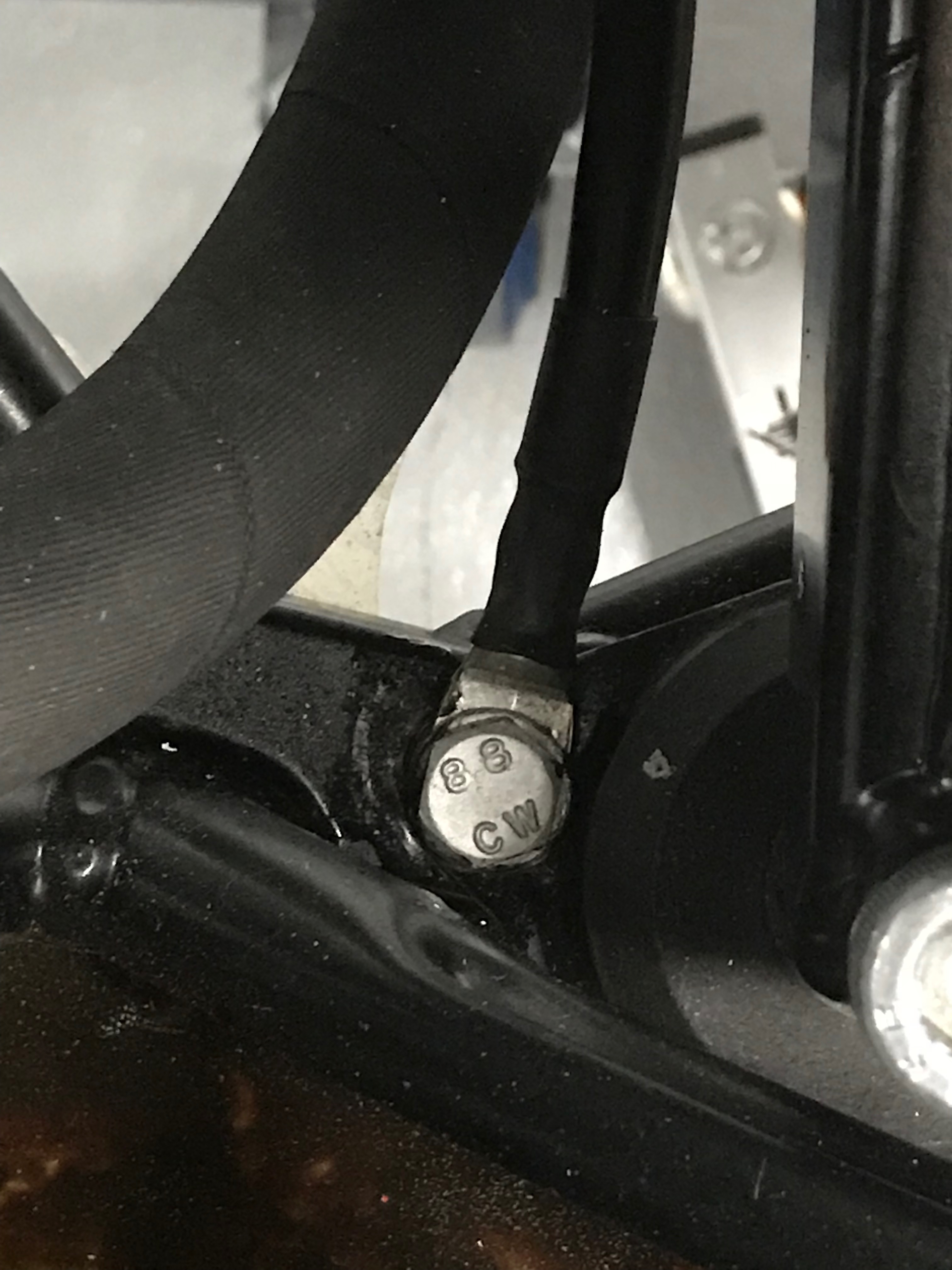
Engine Mounts
I realised over night that I hadn’t actually tightened the engine mounts and painted the earth connection. In the end my earth connection to the LHS engine mount looks like this.
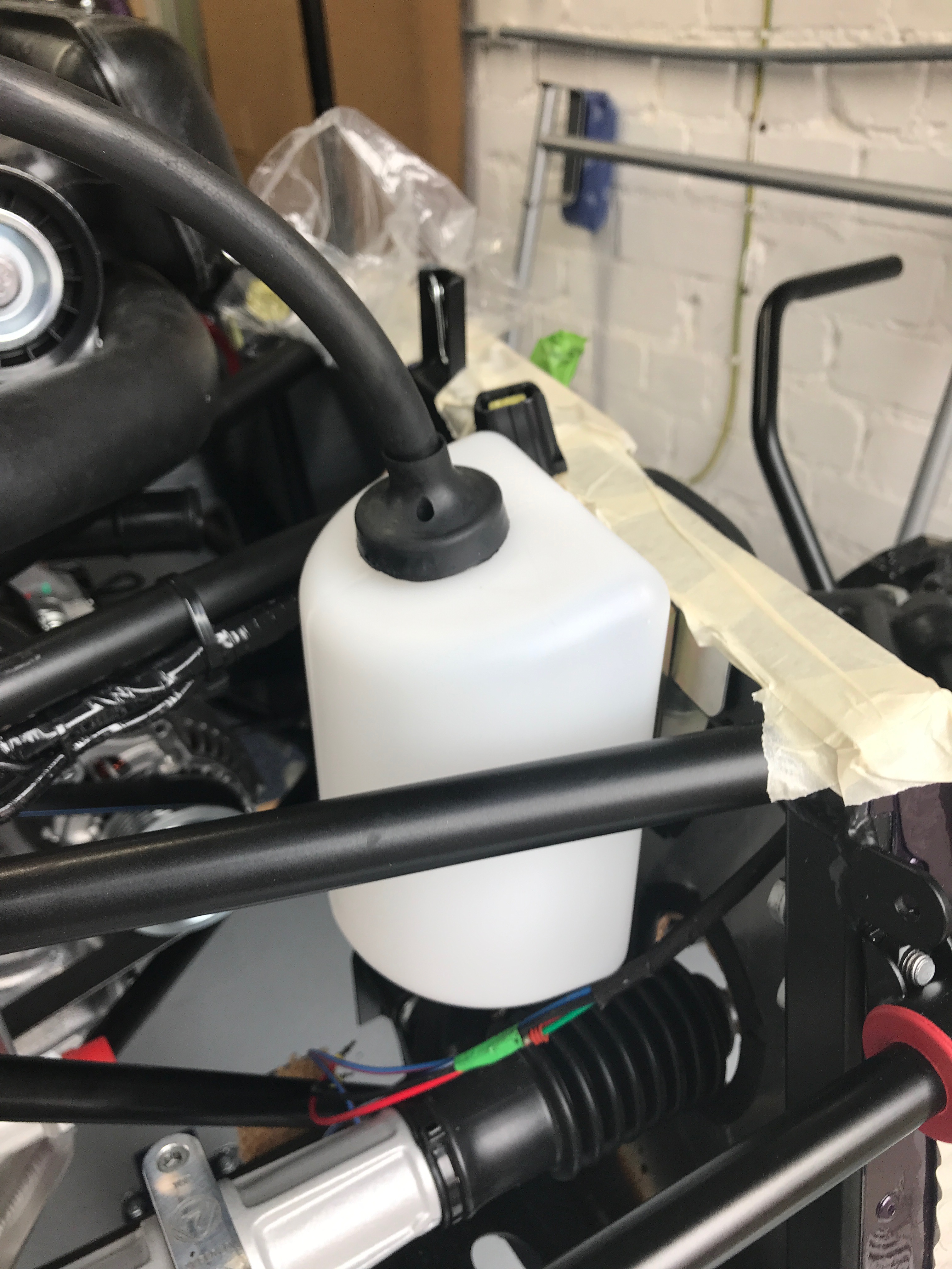
Oil Header Tank
Ok so on to the dry sump oil header tank. The tank drops fairly straightforwardly into a triangular space in front of the engine. There are then four specially formed pipes, a breather pipe from the cylinder head and then a waste pipe to a catch tank.
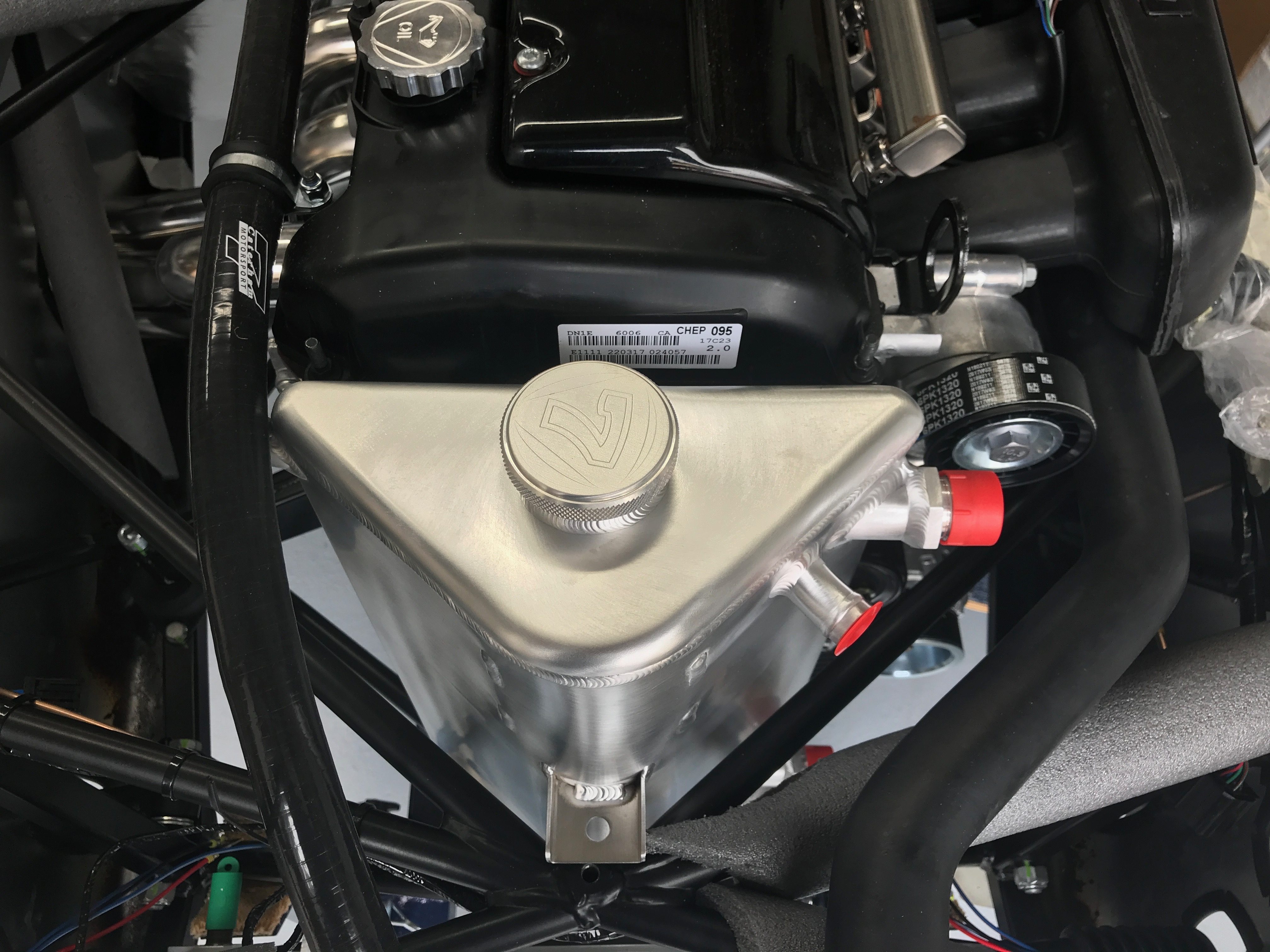
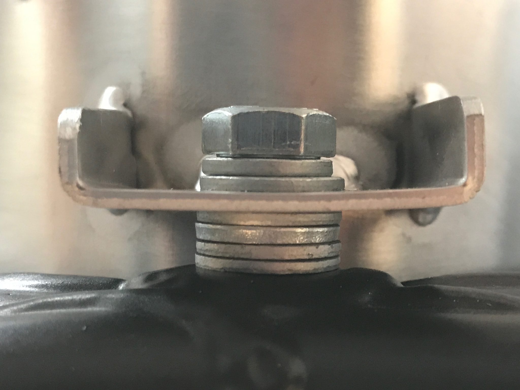
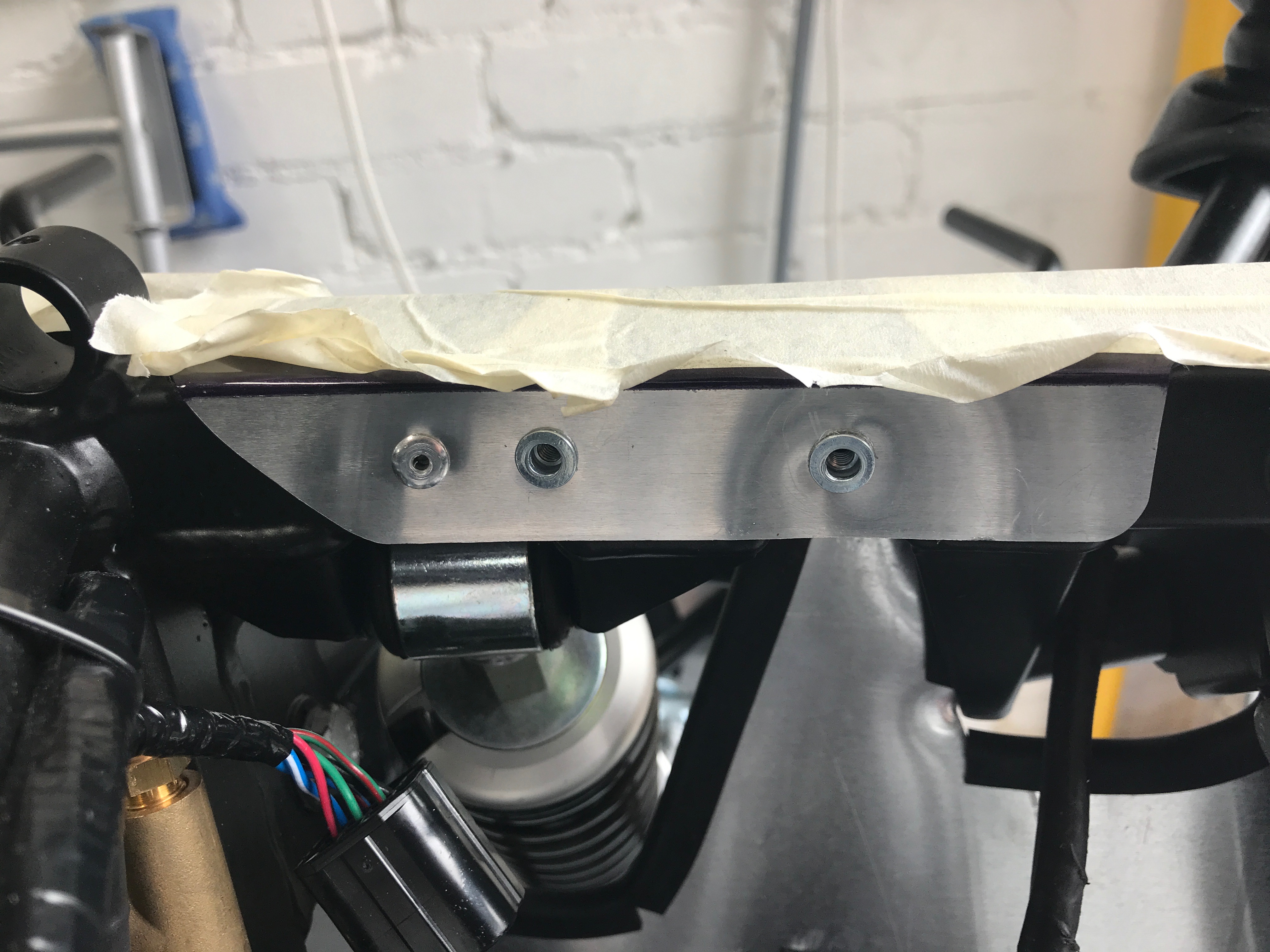
The manual is a little vague about the fixings for this tank but I found an M8 setscrew in misc fastener pack that would work for the top fixing. The tank seems to be a little tall for the space it occupies and so sits a few mm high from the central cruciform point that the top fixing it’s supposed to be bolted to. A few spacing washers fixes that though.
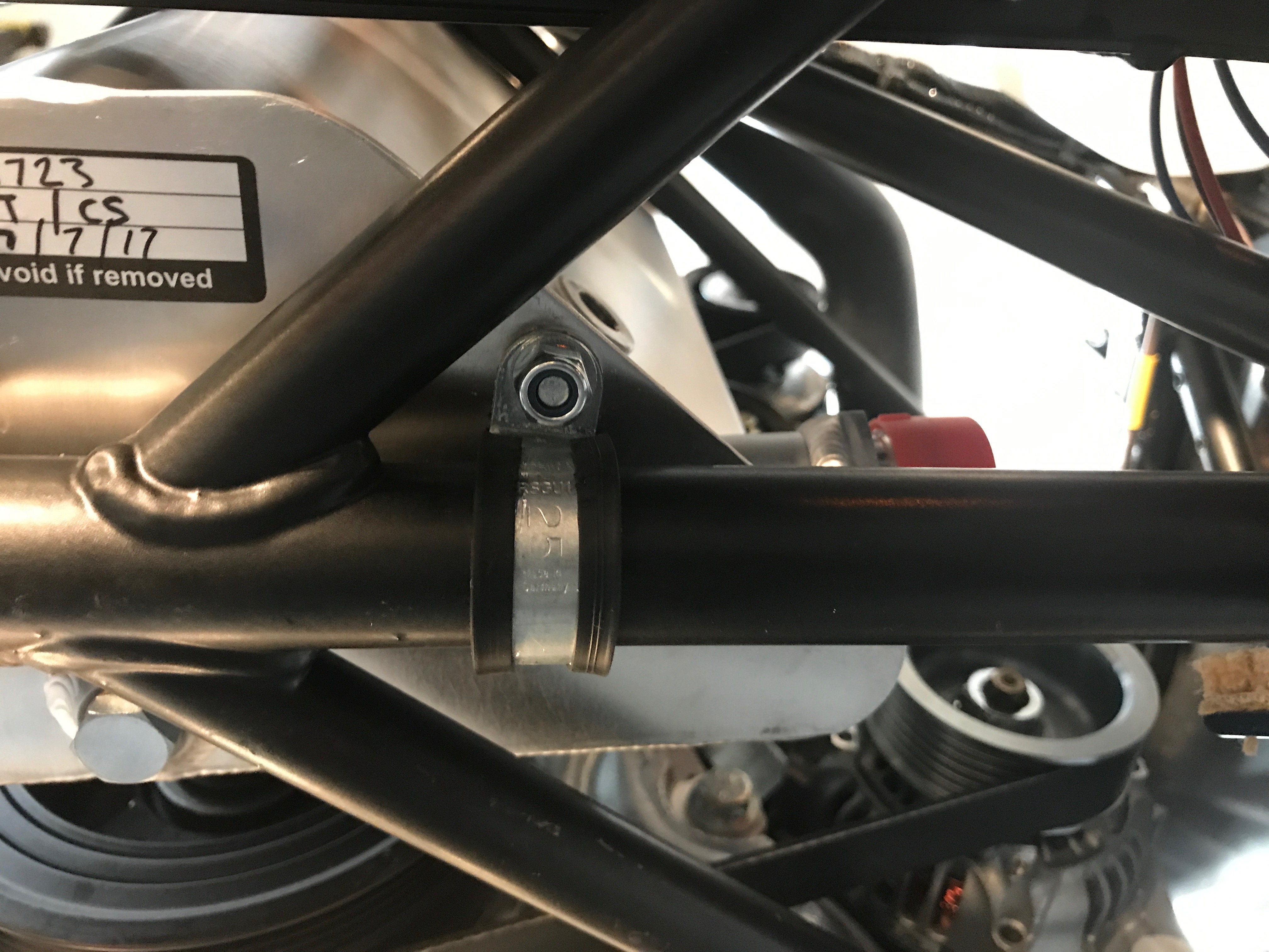
At the bottom of the tank a two holes drilled in the lower flange of the tank. I made another manual error here and didn’t read the final section on fitting the tank and missed that there are instructions to fit p-clips to the chassis rails and to secure the bottom of the tank to these p-clips through the holes in the flange. I faffed around a bit trying to figure out what to do here and eventually emailed Derek.
Email to Derek.
Derek sent pictures. Need 25mm P-clips and that I could use the P-clips from box marked starter motor. Derek said they won’t be used anywhere else.
Had I realised that the P-clips were all part of the manual instructions then I would have soldiered on assuming all the bits were in the kit. In the end I played around for too long thinking I was doing an improv. when actually all I needed to do was assume the kit contains the parts I needed. Note to self, read the manual more thoroughly before each session.
I had 3 stints at oil the tank. Faffing around with non-suppled nuts and bolts. Then realised I hadn’t read the manual and in the end I could use nuts/bolts from misc pack.
I got the tank in on third the attempt. It was the P-clips that caused all the time wastage. Firstly finding them the finding fixings (manual doesn’t say where to find any fixings) and then fitting them. They are tricky blighters to get installed. There must be a trick but I hadn’t found it. Using a pair of grips was clearly the right way to go, getting the radius of the P-clip to be formed by the cross member and the grips. I got there in the end though. I probably took more than 3 hours on the header tank today – and two of those hours were probably wasted in messing around going in the wrong direction, not reading the manual and then struggling to get the clips on.
I used 4 washers as spacers for the top mounting. There’s a washer and spring washer just below the setscrew head.
I could then attach the top oil pipe, that comes out of the back of the cylinder head, to the tank. It needed to be cut to length and then a retaining P-clip to be flipped to drop the pipe down to the height of the tank. There’s about 50cm of pipe that gets cut off and I saved it away in my “might be useful later on box” – note from future self, yes it was useful to connect the oil catch bottle to the oil tank.
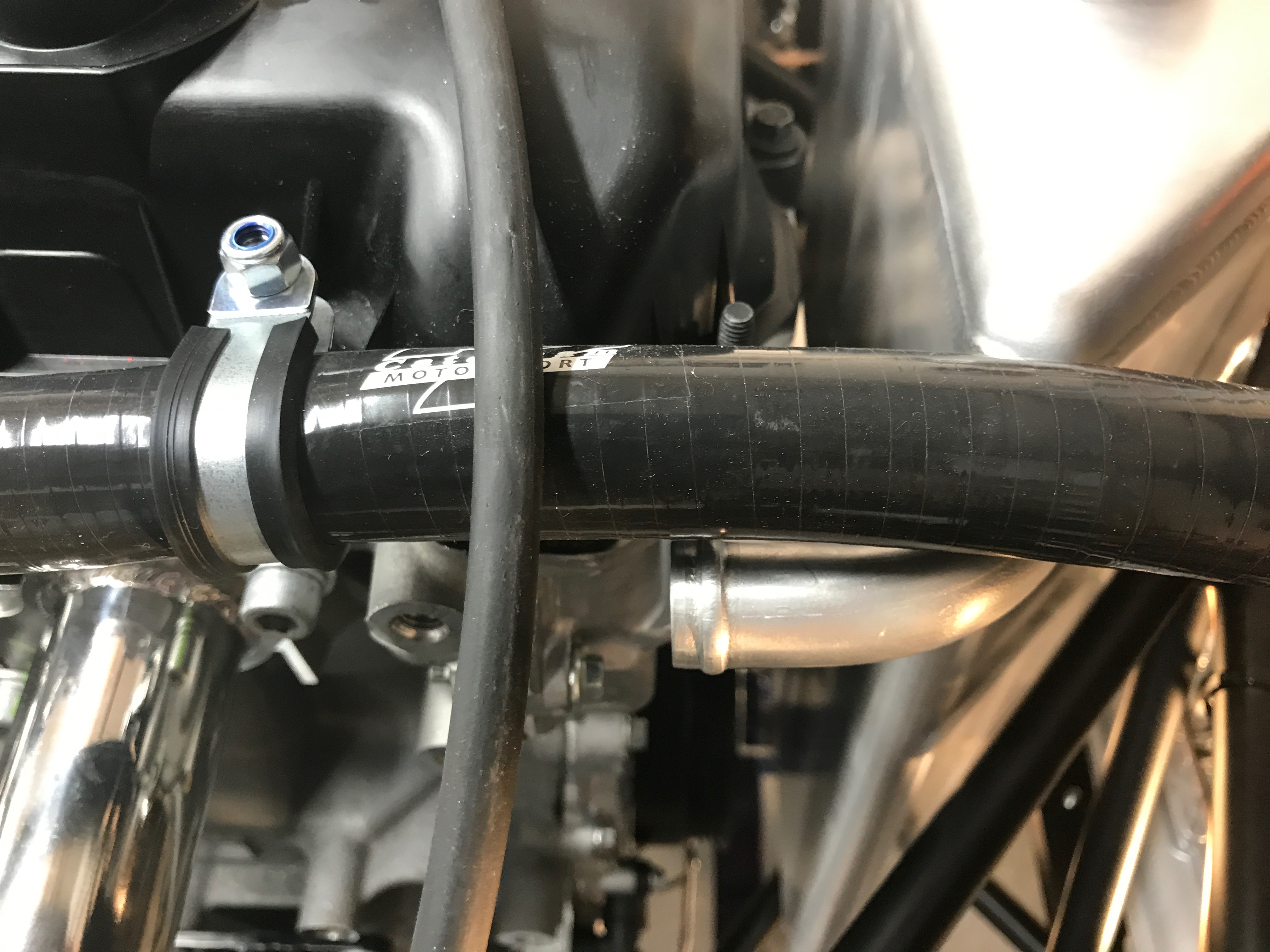
The images Derek sent earlier about the tank mounting seem to vindicate this approach but I also went back to the pictures I took of the 420R over a Williams a few weeks ago. On their top oil pipe they have no P-clip at all near the tank.

Oil Catch Bottle Bracket
The manual says to attach the oil catch bottle to the chassis with rivets. That’s not a problem but I wanted to try and use the rivnuts again. So, I drilled out top bracket holes to 4mm and then drilled 6mm holes in the chassis, drilling out the rightmost rivet in the process. I could then use an m4 rivnut and attach the tank bracket. Seemed to work really well.
The bottle then slips onto the bracket. I still have to figure out how the pipework connects to the oil tank… from what I’ve seen you don’t use the supplied cap and hose.
Steering
Now the primaries are in place we can now fit the steering column. The column is fed through the holes in the dash and rear of the scuttle, through the top section of the pedal box and then into the engine compartment. The bottom of the steering column has a knurled section that fits into a similarly knurled universal joint. The universal joint then slots onto the steering rack.
The plan is to get the cross of the universal joint vertical/horizontal and for there to be as straight a path, for the steering column, as possible.
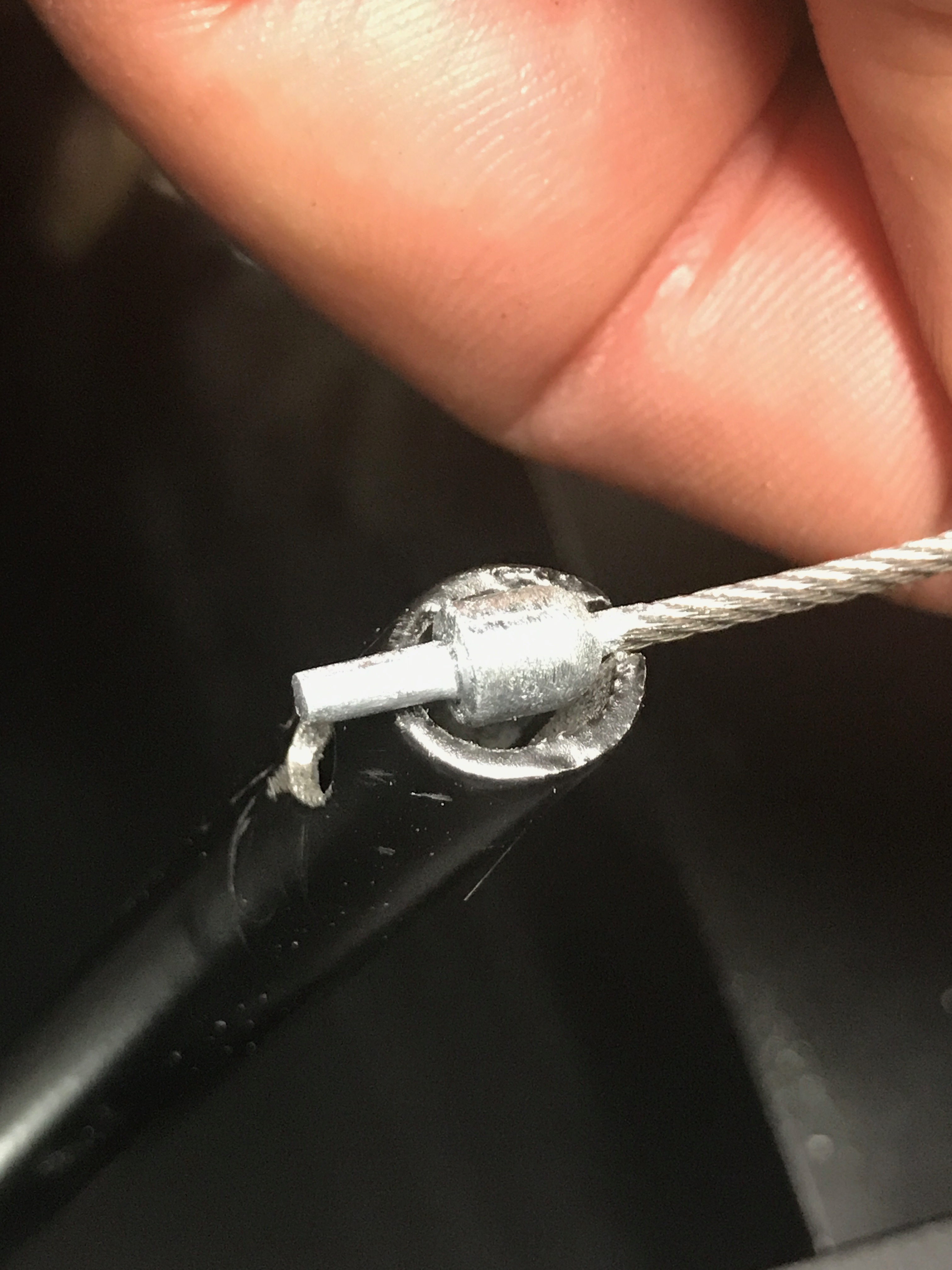
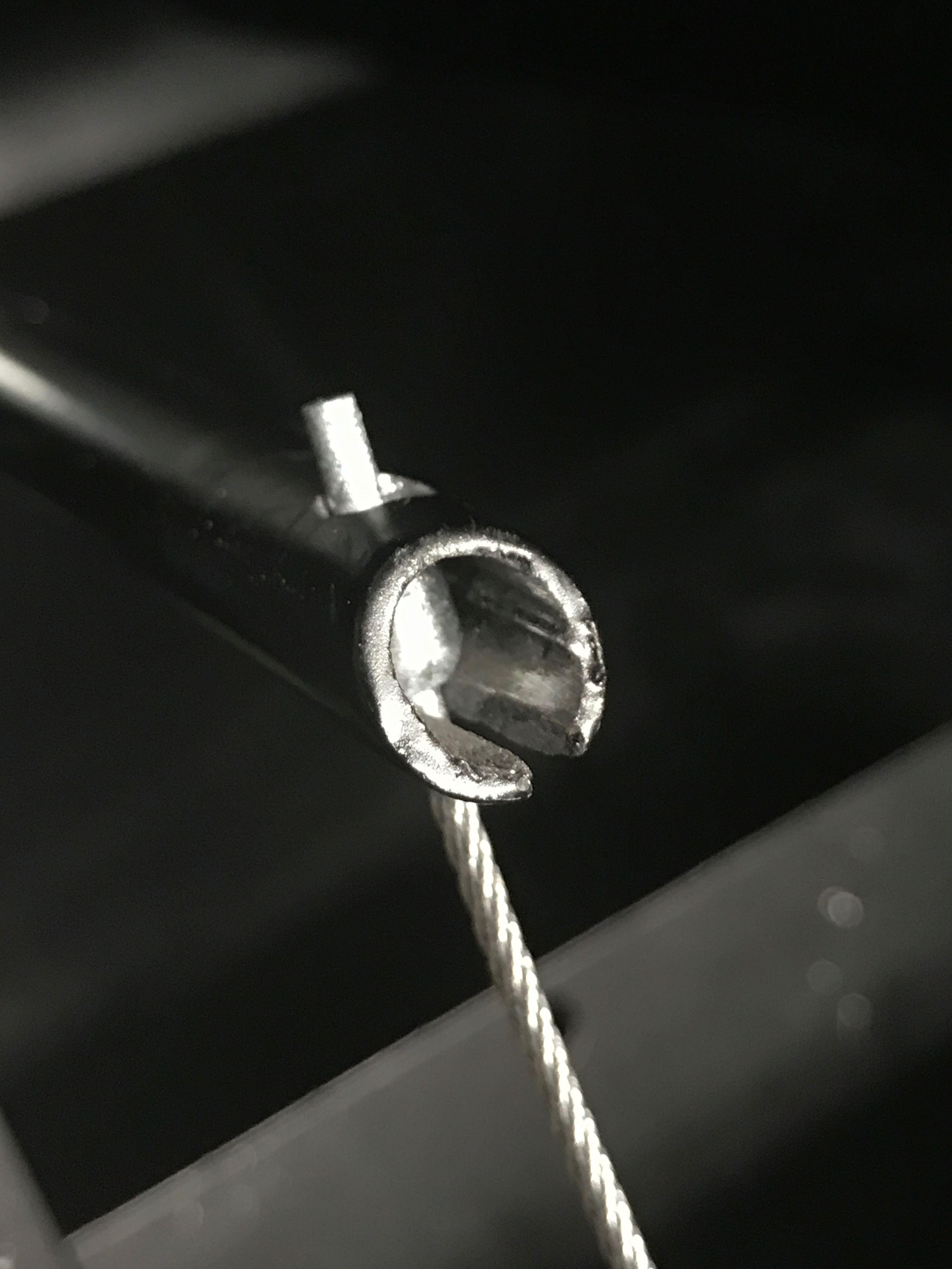
The first problem here was that while the steering column fits into the universal joint fine, I couldn’t get the bolt closest to the steering rack into the joint. There’s a recessed slot in the steering column that holds the bolt captive… so that even if the bolt becomes loose the steering column can’t come out of the universal joint. So I fettled (with a Dremel) the uni-joint and painted it with two coats of hammerite… that took a fair part of the afternoon in-between other jobs, two hours between coats plus final drying time.

The second issue I found on the steering column was that I seemed to be missing a setscrew that is used to fix a collar around the upper and lower steering columns.
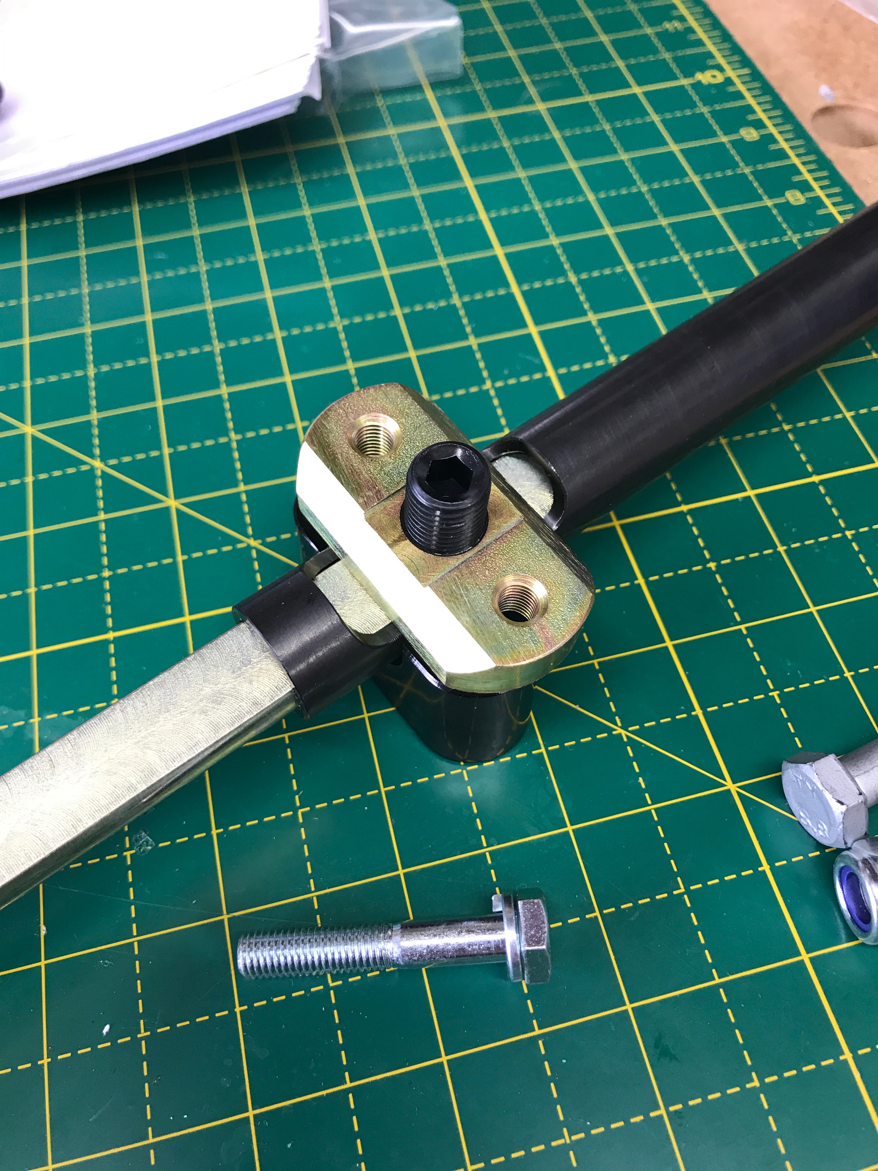
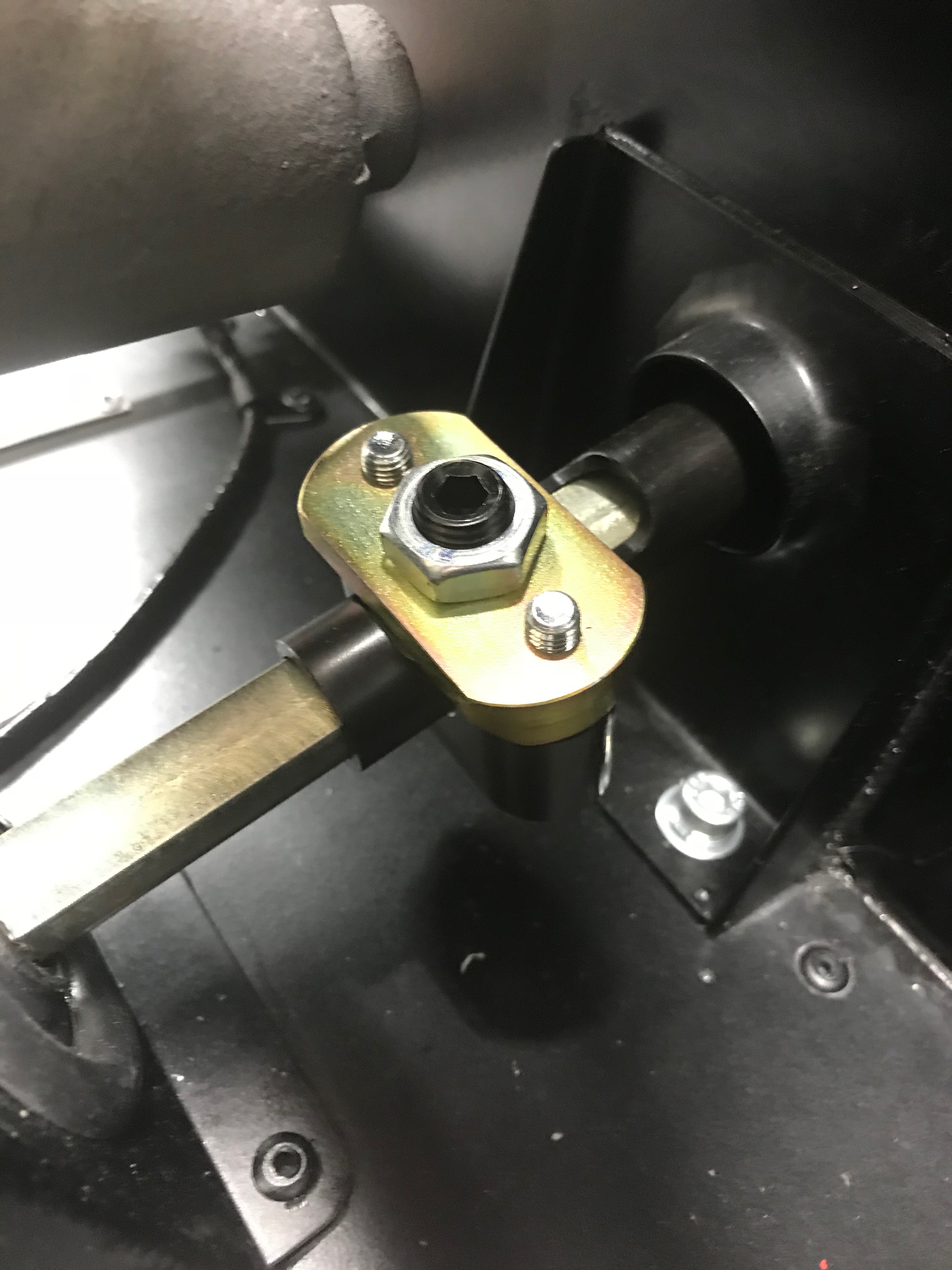
I emailed Derek and the missing imperial setscrew was sent out. The lower column has a half round cross section at its top. The upper steering column is hollow but has a recess in it so that when the lower column is slide into the upper column there’s a gap in the upper column that the collar can sit around. That all sounds too complex for words, so I’ll insert an image from later in the build here so you can see what’s going on.
A quick aside on this steering column arrangement. I think this is peculiar to the quick release steering wheel setup. The upper column slipping over the lower column allows some form of collapsibility, which seems to mean that an additional crushable box in-between the steering wheel and column is not required when going through IVA if you have this quick release wheel.
Back to the build… While the universal joint was drying I could continue with the steering. I fitted the lower steering column through dash. As the column slides through the dash and pedal box it naturally wanted to sit up against the primaries. But once seated in uni-joint it was routing correctly away from primaries and doesn’t look as though it will make contact.
The upper steering column also goes in through the dashboard.
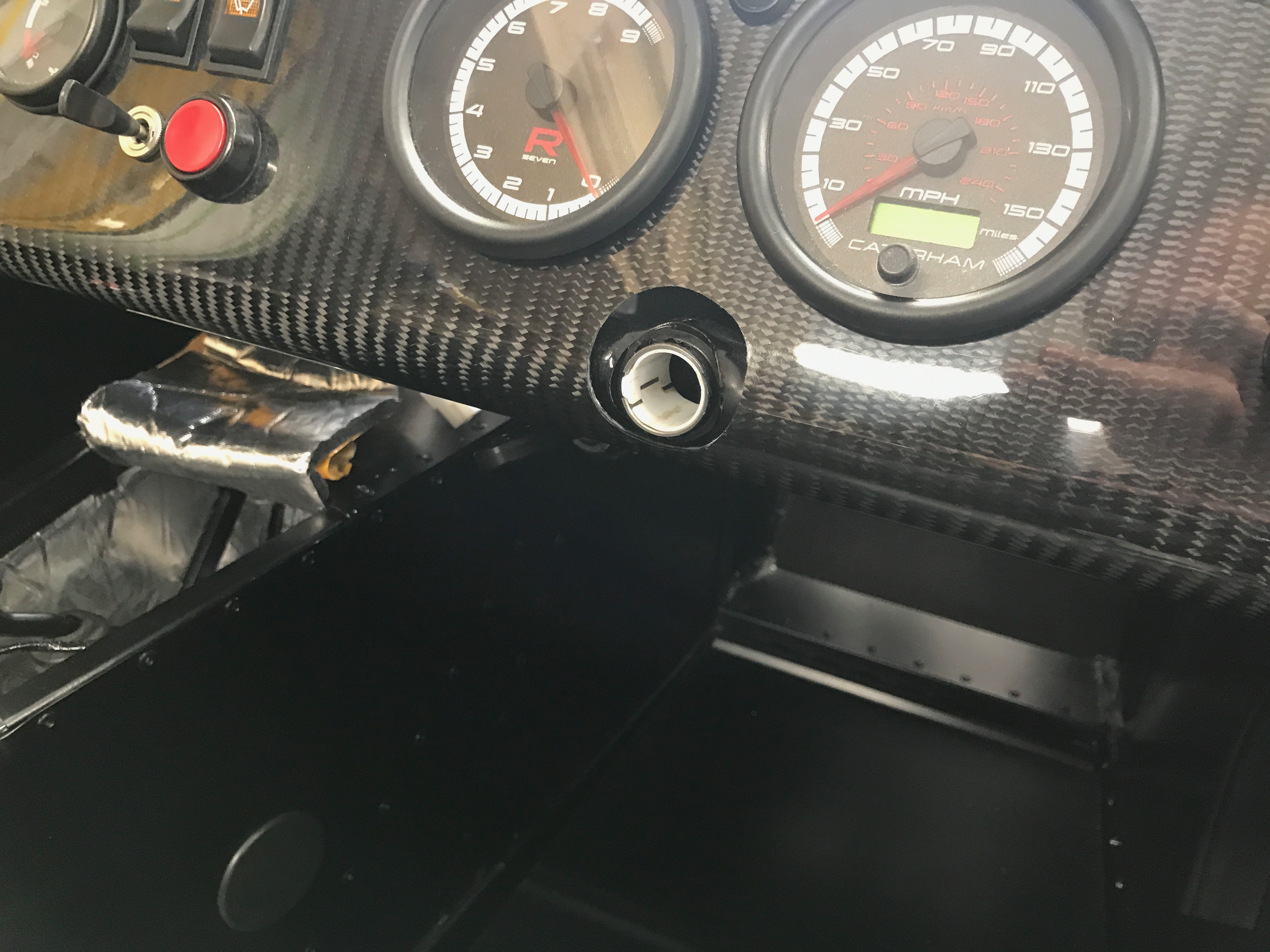
There are two polythene bushes used here to provide a bearing for the steering column, one is in the engine-bay side of the scuttle and the other is on the passenger compartment side of the dash. The upper steering column goes through the bushes which keep the steering column in place at its top. The engine-bay bush is already fitted to the car, the passenger compartment one has to be fitted. I first tried to fit this upper polythene bush onto the column and then feed the column and bush through the dash. But that didn’t work well with the quick release etc. So, pulled the poly bush off the column and seated it in the dash on its own. Lots of PTFE lubricant on top both poly bushes and both rubber grommets in the pedal box and cheese wedge. The upper column then slipped through the two bushes with no problems.
Steering Wheel
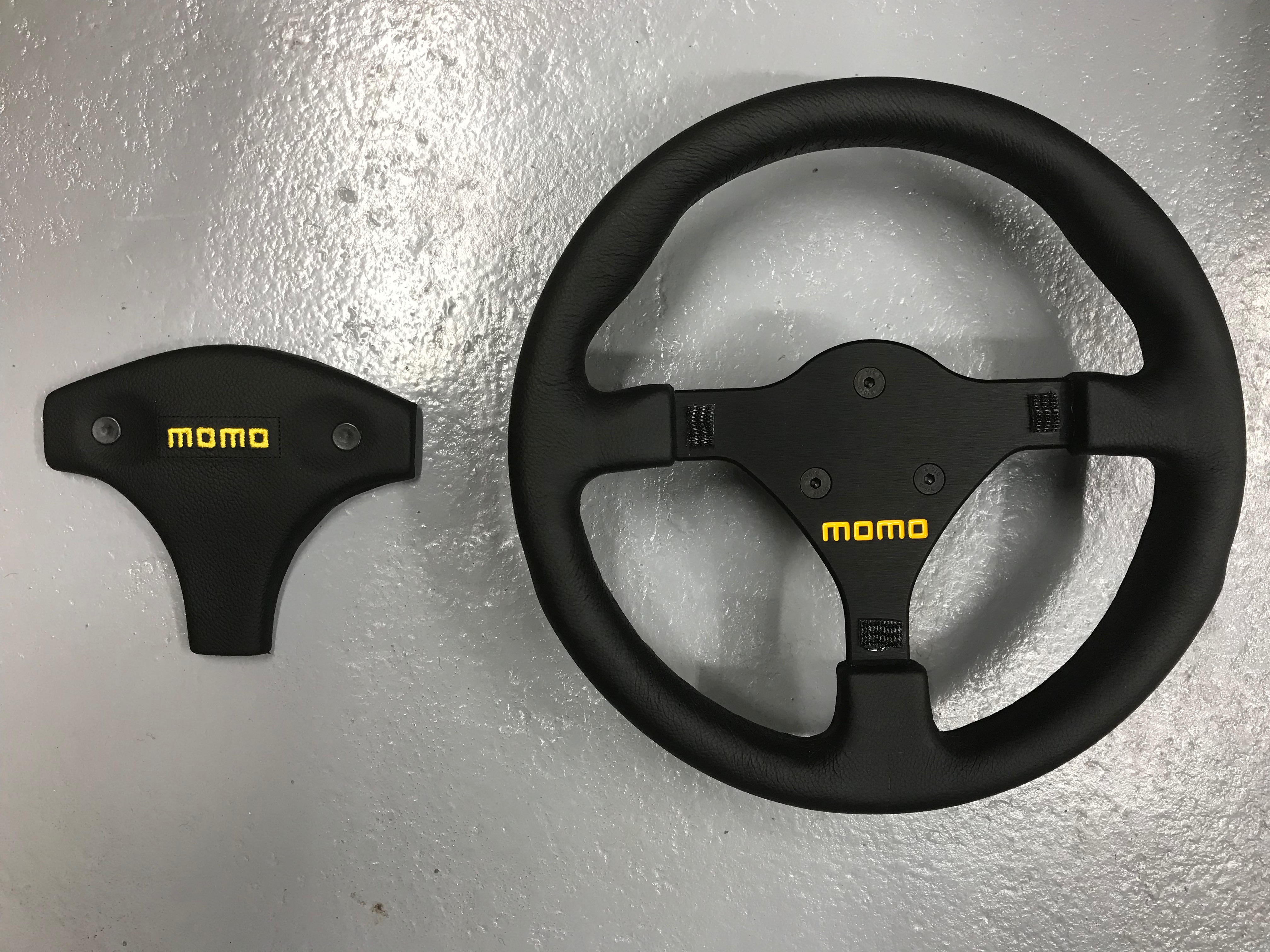
The Momo steering wheel is great. Perhaps not quite as nice as some of the suede trimmed ones I’ve seen but none-the-less this wheel is nice.
However, there is a three pointed pad that is velcroed to the rest of the wheel and which covers the screws holding the wheel to the quick release mechanism…. and… as I took the pad off the rest of the wheel it was clear that only two of the three velcro pads were glued in place. One side of one of the velcro pads had come away from its glue pad.
B&Q and The Tip
Now… While waiting for paint to dry I could have got on with other things but I needed to go to the tip and to B&Q anyway. I wanted to get some silicone sealant as there are bloggers who have used it in various places. I could also go looking for some double sided sticky pads that I could fix the steering wheel with. Imperial drill bits were also on the list but in the end they don’t do them any more. I needed the imperial bits because I’d tried to use some of the imperial diameter rivets with a slightly oversized metric drill bit to create the rivet hole, but the rivet had pulled through the hole… I needed the right sized bits. In the end I ordered a set from Amazon.
I also made a trip to the tip to get rid of some garden waste – killing a bit of time instead of watching paint dry on the universal joint.
When I’d got back from my outing I looked at the oil tank bottom fixings again. And so after a couple more unsuccessful stints at the oil header tank the paint had dried and could fit the universal joint. I twisted the steering rack to line up better with the steering column. For best steering feel the rack spigot needs to point directly up the steering column and the uni-joint cross needs to sit vertical/horizontal when the steering is straight ahead. Torqued uni-joint up to the requisite 20Nm. It also meant I could finally tighten the bolts on the steering rack.
Fixed the Steering
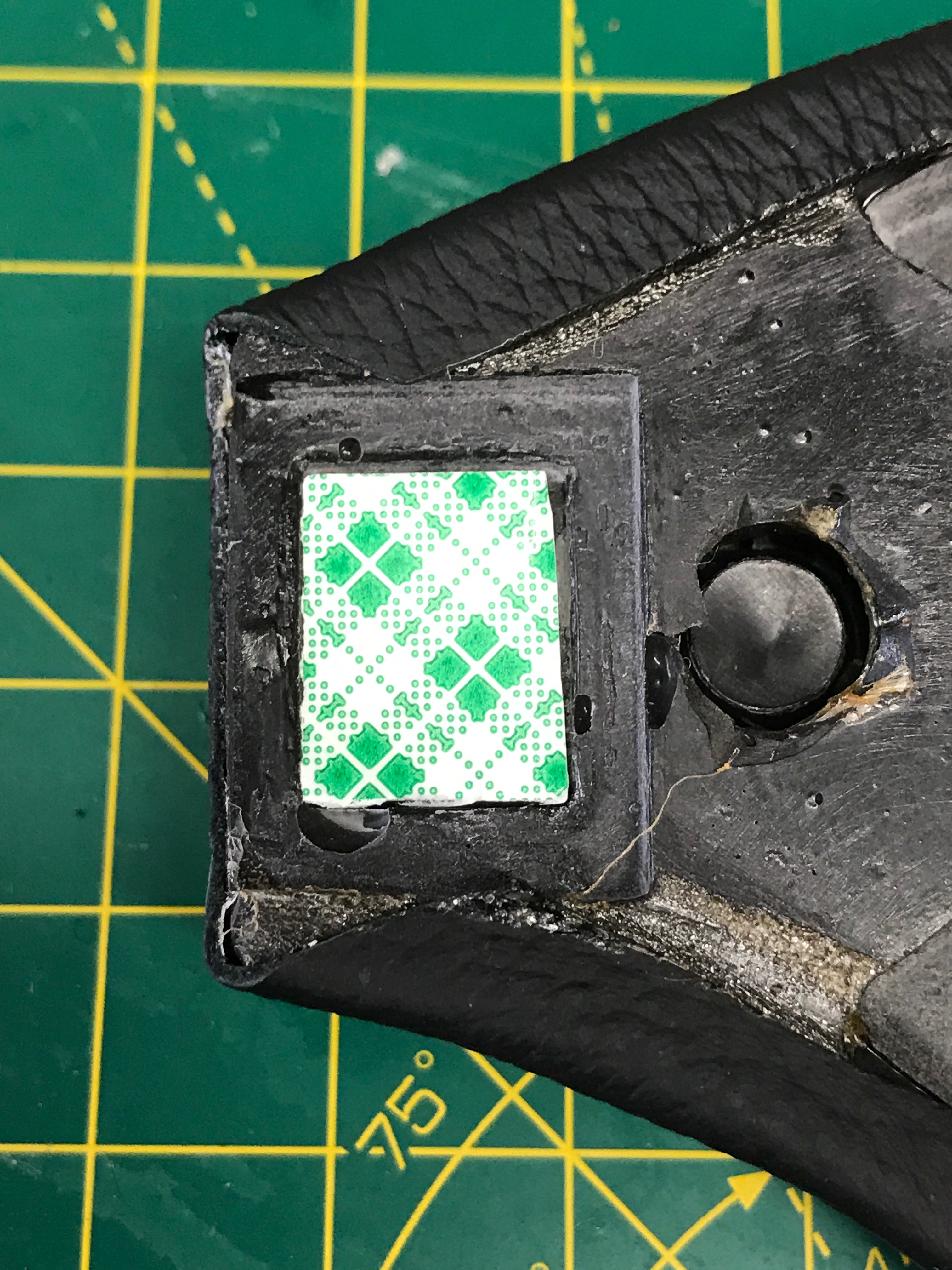

The velcro had come away from the wheel, so I scraped off the glue pad from the wheel and applied my new double sided pad to fix it. Job’s a good ‘un!
Throttle Cable
The manual says that while you have the pedal box cover off, fitting the steering column, you should fit the throttle cable and brake light connections.
The brake light connections were already on in my kit but the throttle cable needed fitting.
Lots of people have talked about he throttle cable being too long and needing to snip one end off and fit with an electrical screw terminal. More on that later.
The throttle body end of the cable went in with no trouble. The pedal end was a different matter.
The throttle pedal shaft has a slot and hole arrangement at its top. The end of the cable has a nipple with a small shaft and a rounded dome, both moulded together. The nipple is supposed to be thread through the frontmost slot of the throttle pedal shaft and into a hole.
The pedal shaft slot and hole are clearly meant to receive the nipple but pushing the nipple down into the pedal shaft. However, there wasn’t enough clearance for this arrangement to pivot into place.
So, initially it was out with the files. I thought there might be some burs clogging the hole. After a while of filing it was obvious that more drastic measures were needed and I got the Dremel out. I opened up the hole and this allowed the nipple to do it’s pivot thing and it was securely locked in place.
I was careful with the Dremel to make sure I didn’t open the hole out too much. This would allow the possibility of the throttle cable escaping the pedal shaft. I have it set so that its easy for me to take it out but I think highly unlikely to pop out by itself. The manual says to crimp the pedal shaft slot to stop the cable escaping, but that seems like a poor long term plan. I’ll see how the fixings stay in place over time and maybe crimp it up if its a problem.
Even though both ends of the cable were in place there was still slop in the accelerator pedal. There are three adjustment points on the assembly. There’s a threaded stop on the chassis for the upper travel of the pedal. There’s a threaded stop behind the pedal for the lower travel (pedal fully pressed) and there’s the adjustment of the cable which sits at the throttle body end.
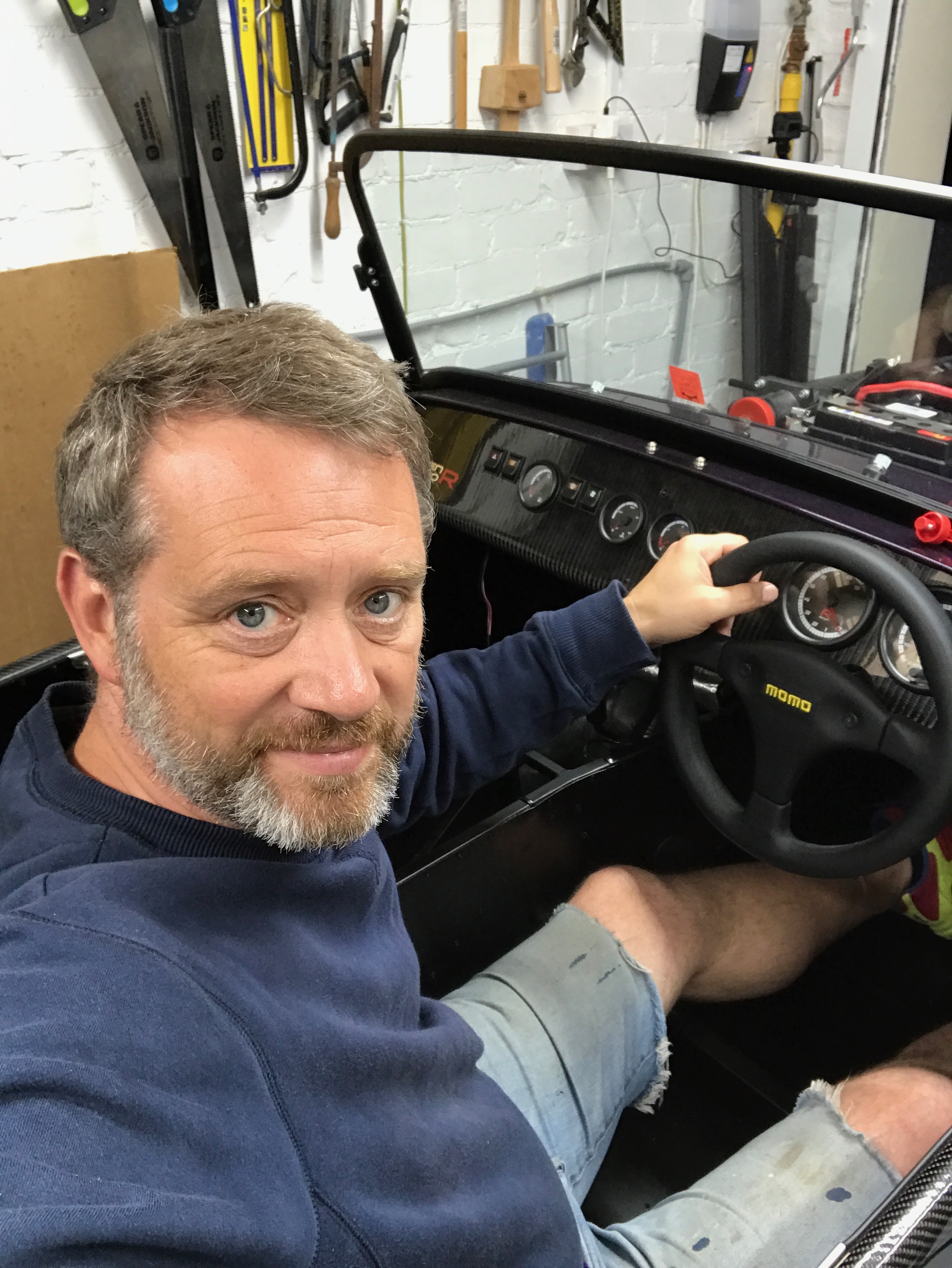
I played around with the cable adjustment a bit but it was clearly going to take some finessing and I decided I’d leave the adjustment to another day and to therefore leave the top off the pedal box for the moment. The generally accepted solution is to bend the throttle pedal shaft to take up the slack, but I wasn’t quite ready to do this yet. I did sit in the car for the first time to test out the acc. pedal at one point… I’d been itching to do this for days but hadn’t succumbed until now.
In the end my PTO day saw me spend an elapsed 12 hours on the car and visiting B&Q and the tip. However, totting up the actual time spent I only got 7:45 of actual build time.
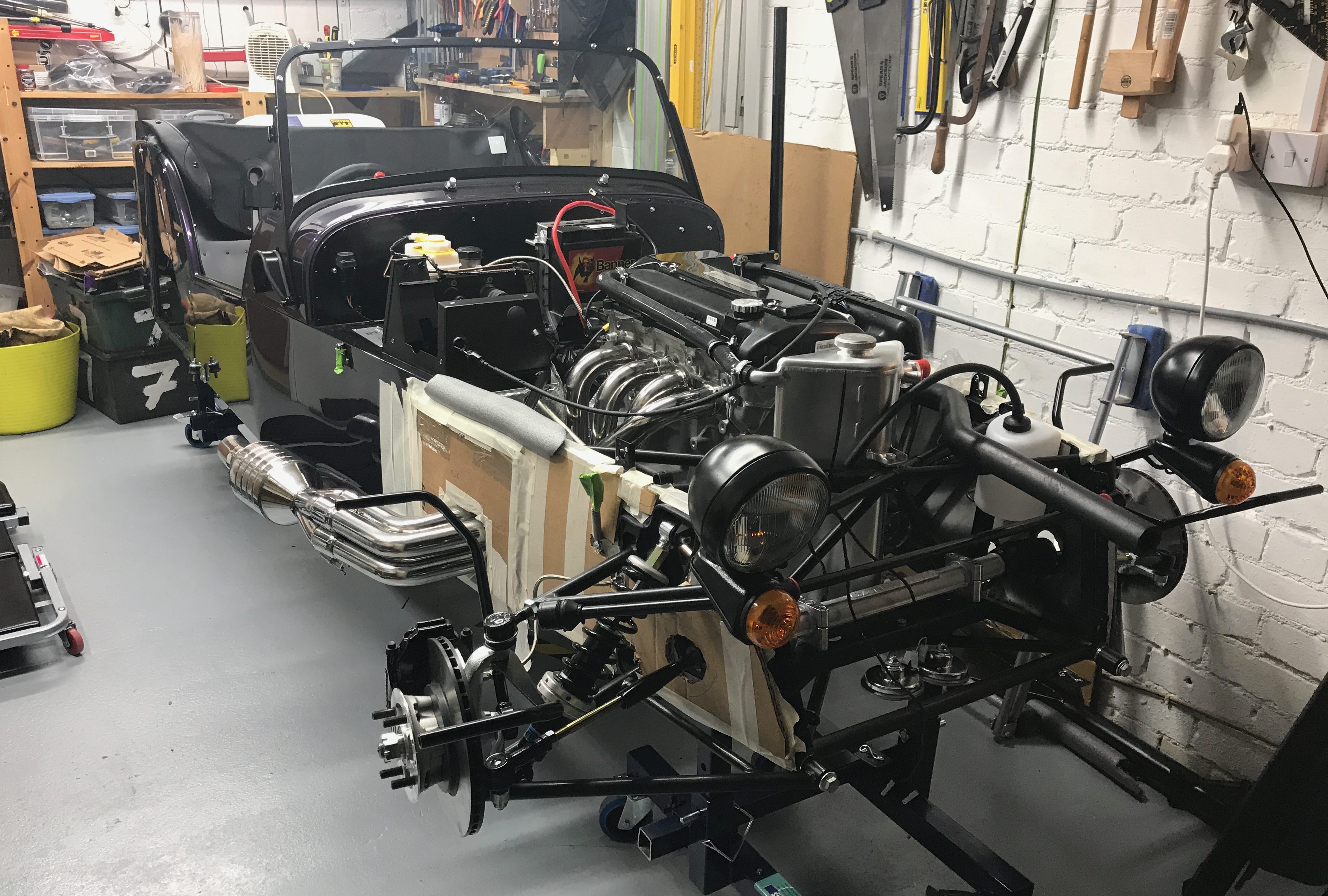
And this is how it looks at the end of today…

Leave a Comment