
Before getting into today’s session lets have a bit of a recap on progress. Of the 90 tasks I have on the project plan, we have 36 tasks completed. And there are a few tasks on the plan that we’re not going to need to do thanks to Caterham doing them already, like weather gear and a lot of the interior trim riveting. I don’t think there’s any point in trying to work out a percentage of work done, as some tasks are trivial and some major. However, it has taken 23 elapsed days and 11 build sessions to get here so far.
I’m also noticing that I seem to be unusual in that I’m following the plan. Many other builders seem to chop around the build. Perhaps that’s because they are missing parts… which I think is more a thing of the past. Sure, there have been things missing from our kit but considering the complexity of the kit and the number of options, I’m amazed they’ve got it as sorted as they have.
On the build-order point: I’ve seen a few bloggers put the differential and prop shaft in before the engine… that seems a little nuts to me. It’s got to be more difficult to get the engine onto the end of the splined prop shaft while the engine is dangling in the engine bay. It was difficult enough to get the engine located without having to marry it up to the prop as it goes in.
On with the build…
Header Bolts and Gasket
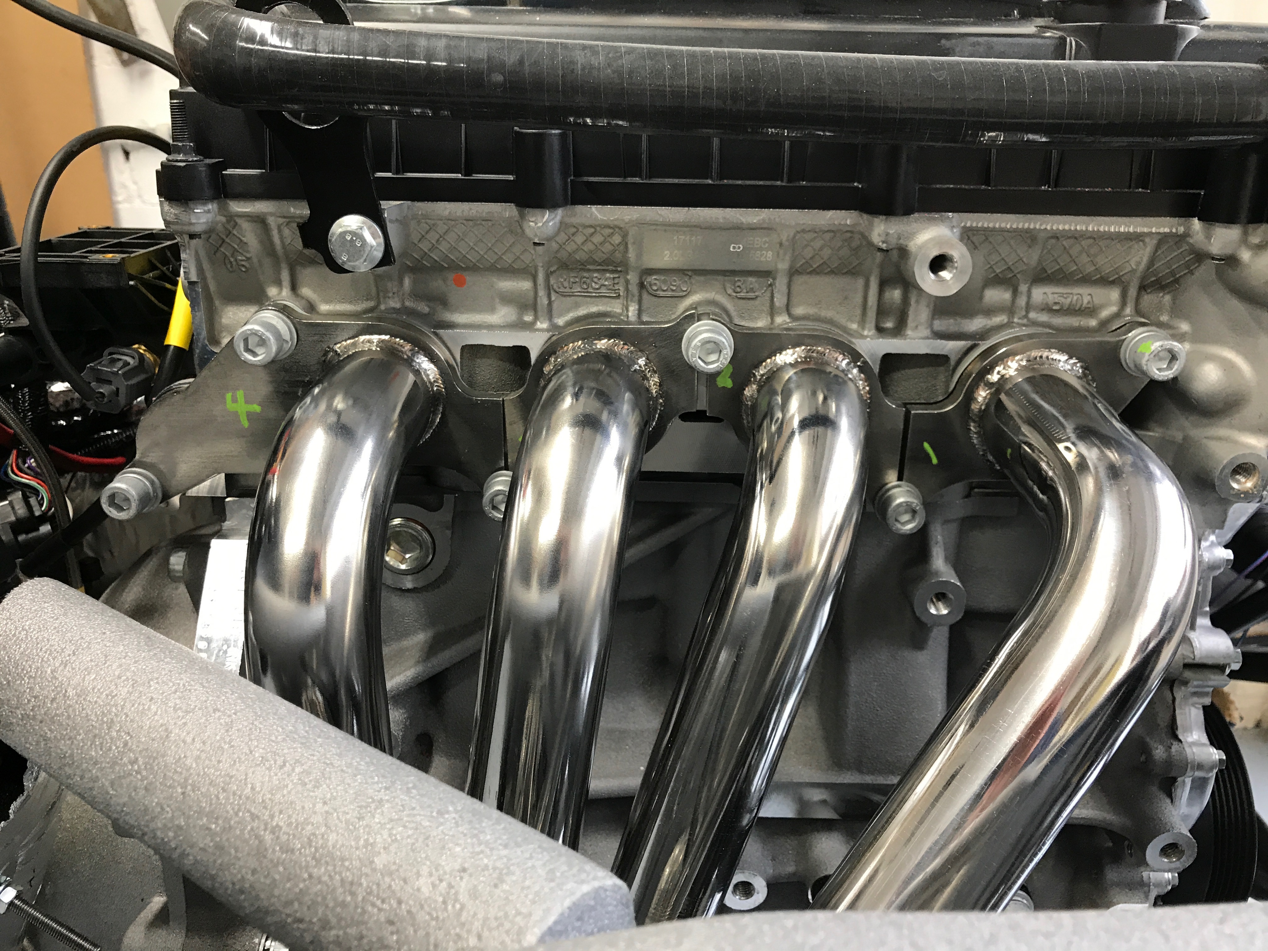
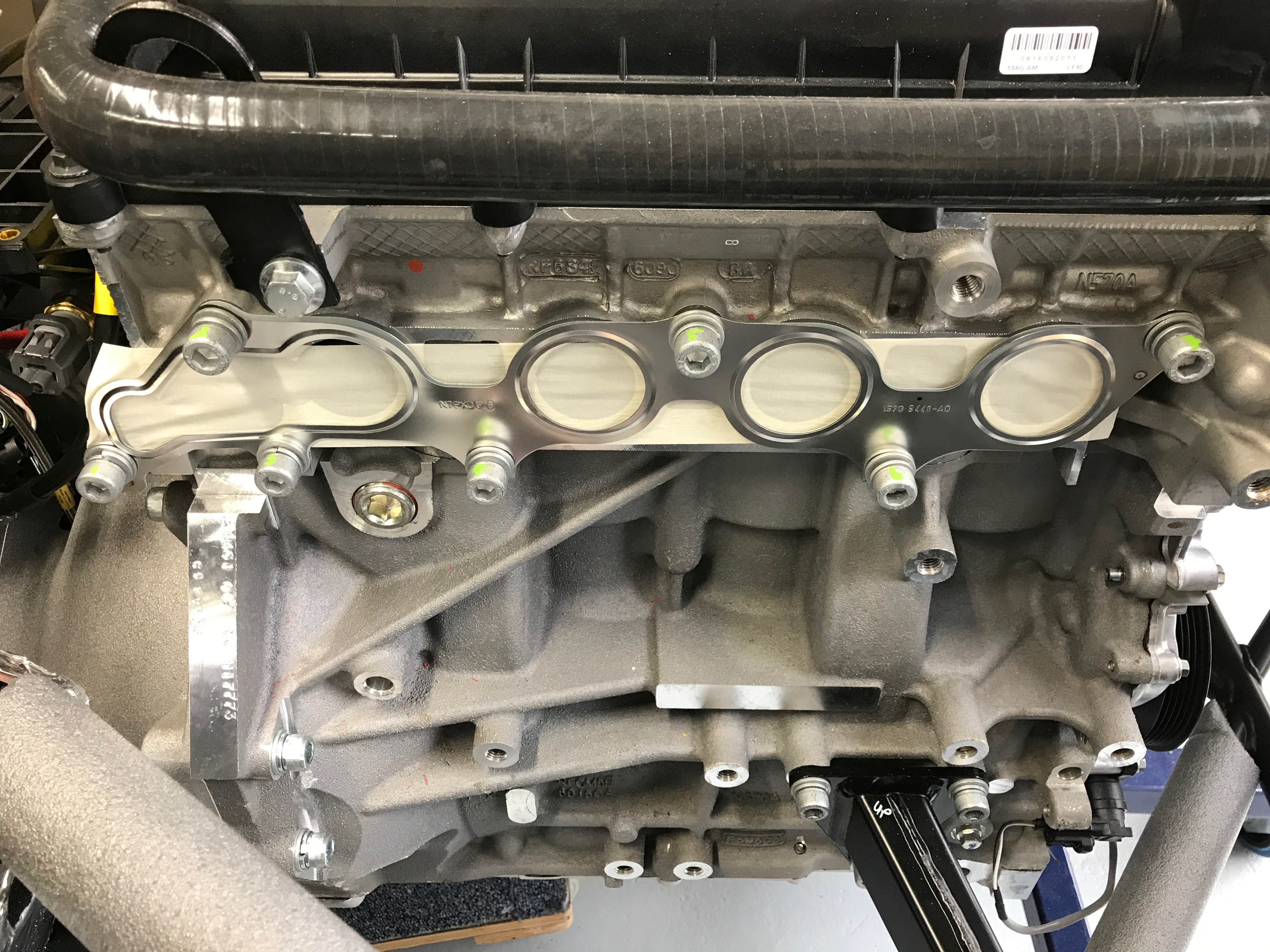
One of the main jobs today is to get the exhaust primaries on. The exhaust ports on the head are covered with tape and with the exhaust port gasket… I’d normally be thinking “manifold gasket” but it’s really four manifolds, or primaries, but one gasket. The manifold bolts are already in the head holding the gasket on.
Perhaps I was being a bit OCD at this point but I didn’t know whether the manifold bolts were going to be different lengths so I numbered them just in case I got them mixed up. Turns out they are all the same length.
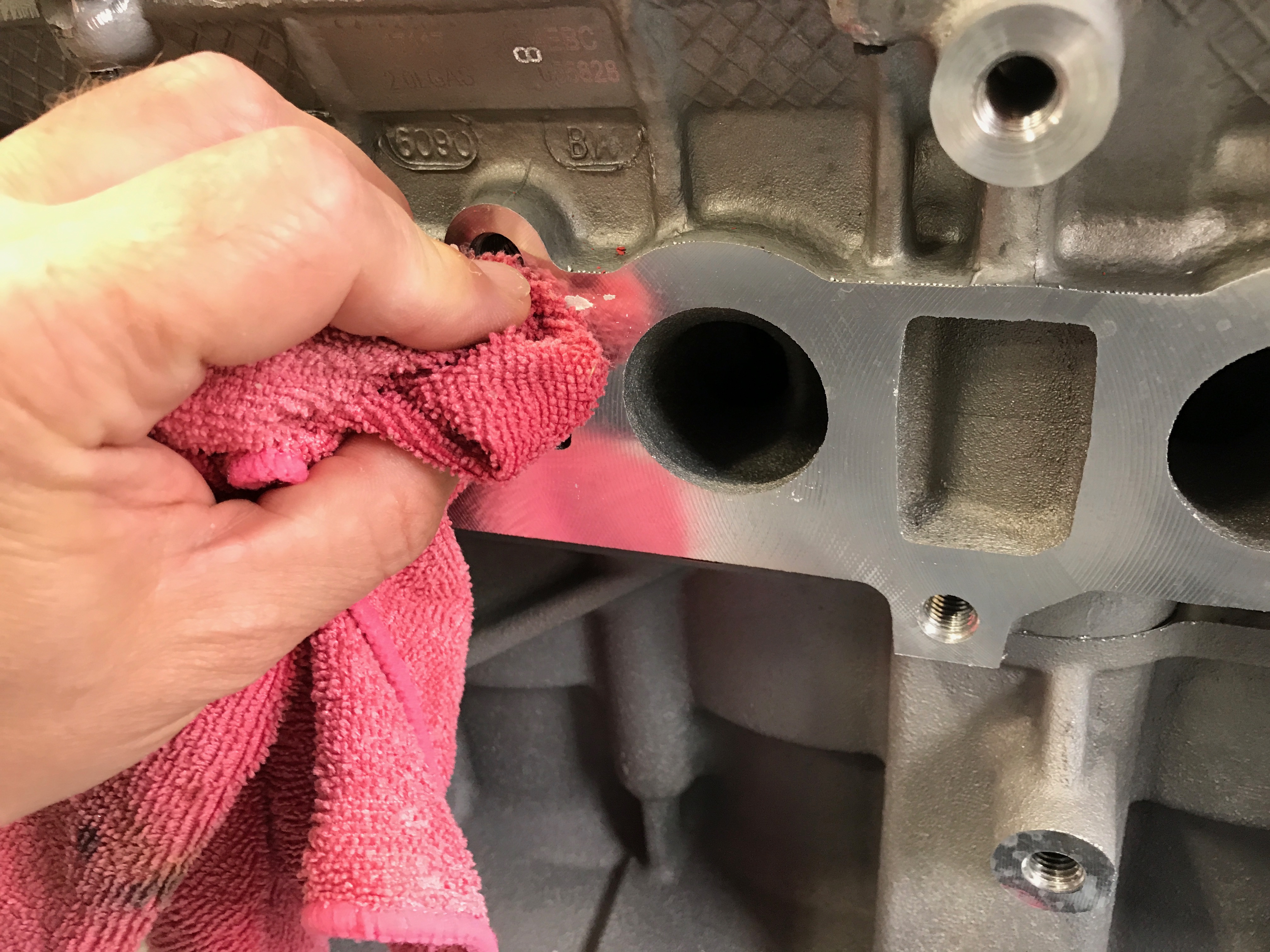
The exhaust gasket is only loosely attached so drops off. However, there is masking tape covering the exhaust ports which peeled off but left tears and residue on the cylinder head. I removed any glue residue with petrol.
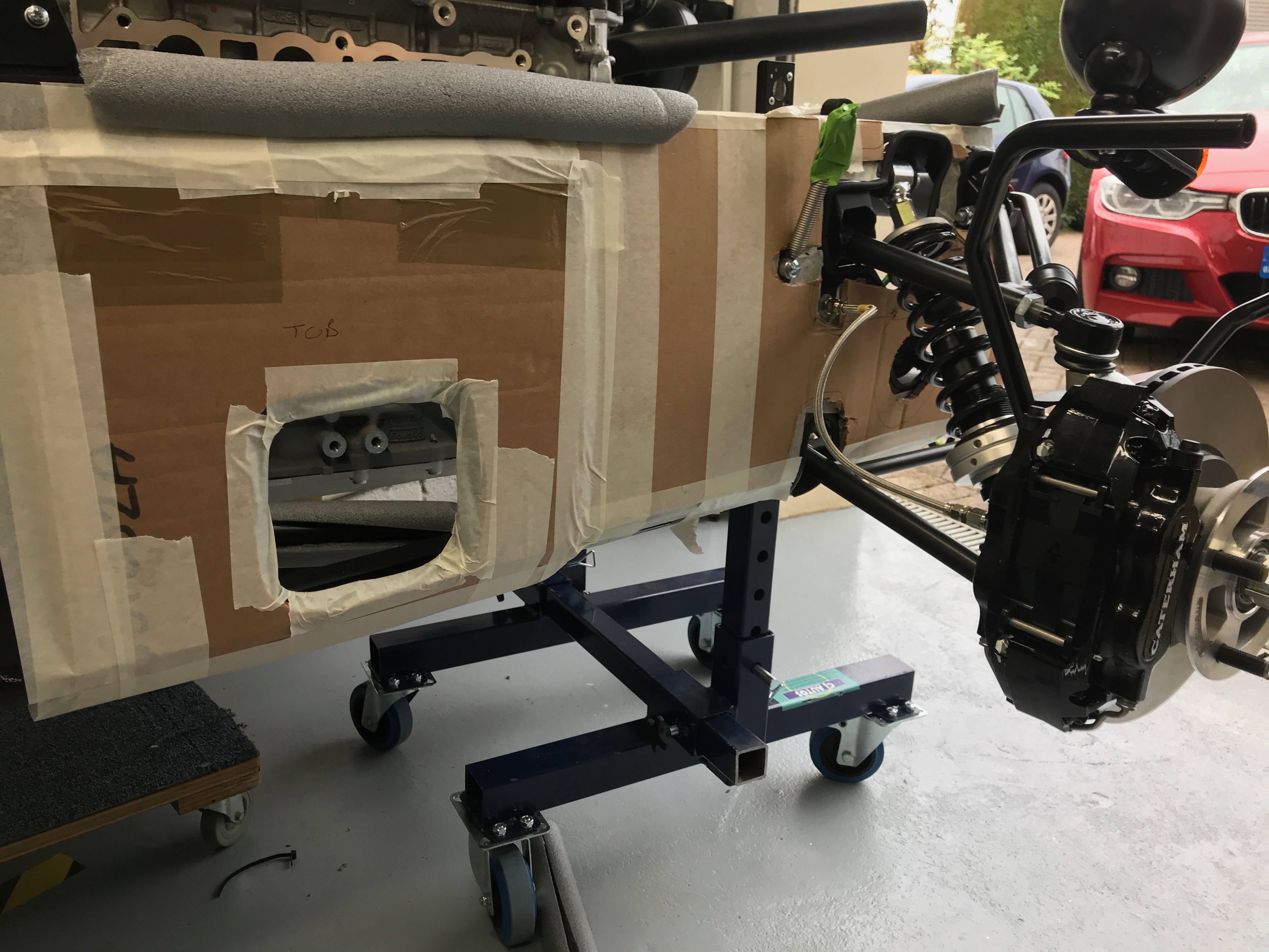
At around this point the manual tells you to make sure there is protection around the hole where the primaries exit the engine bay. Cue more cardboard and masking tape.
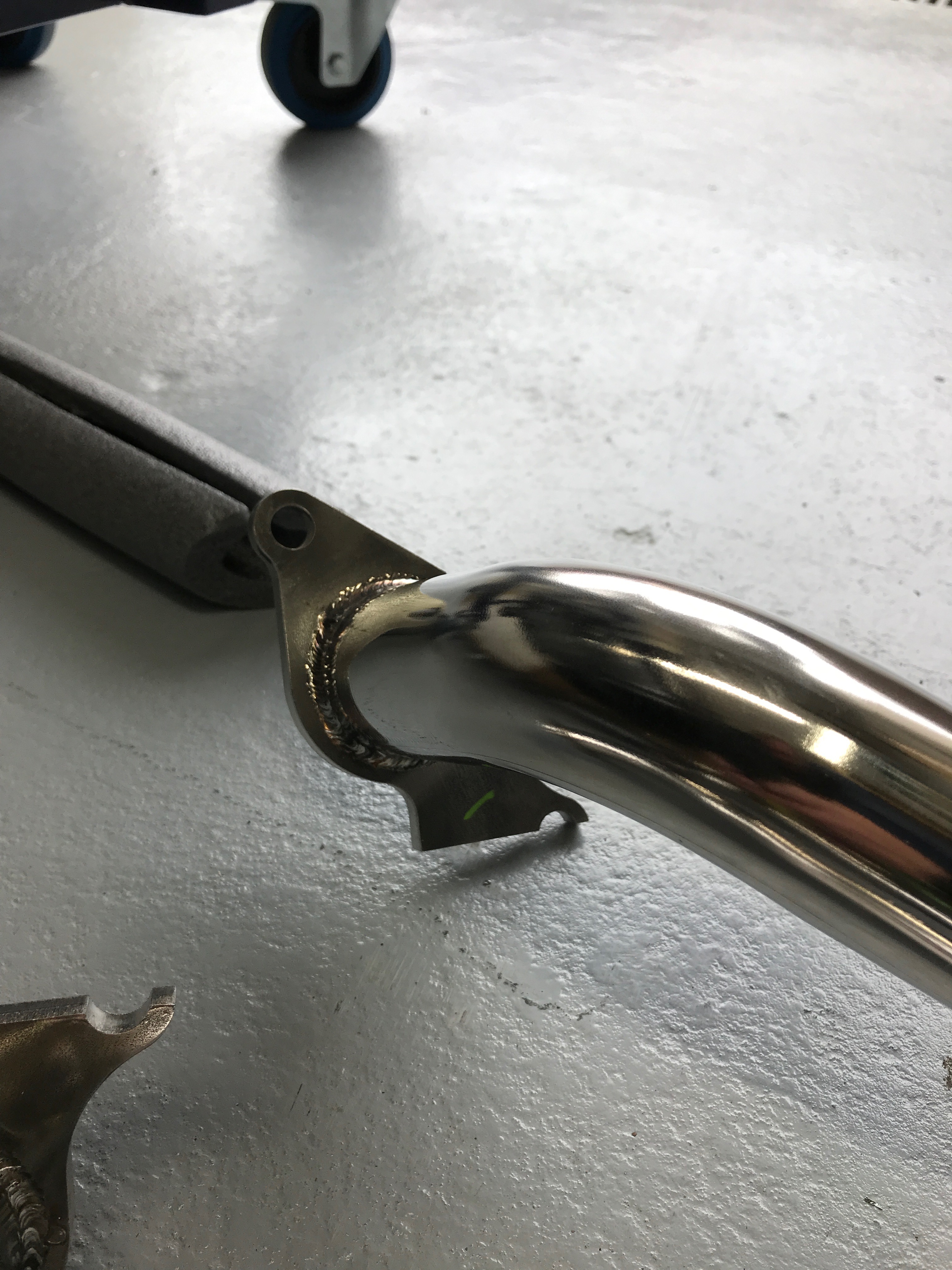
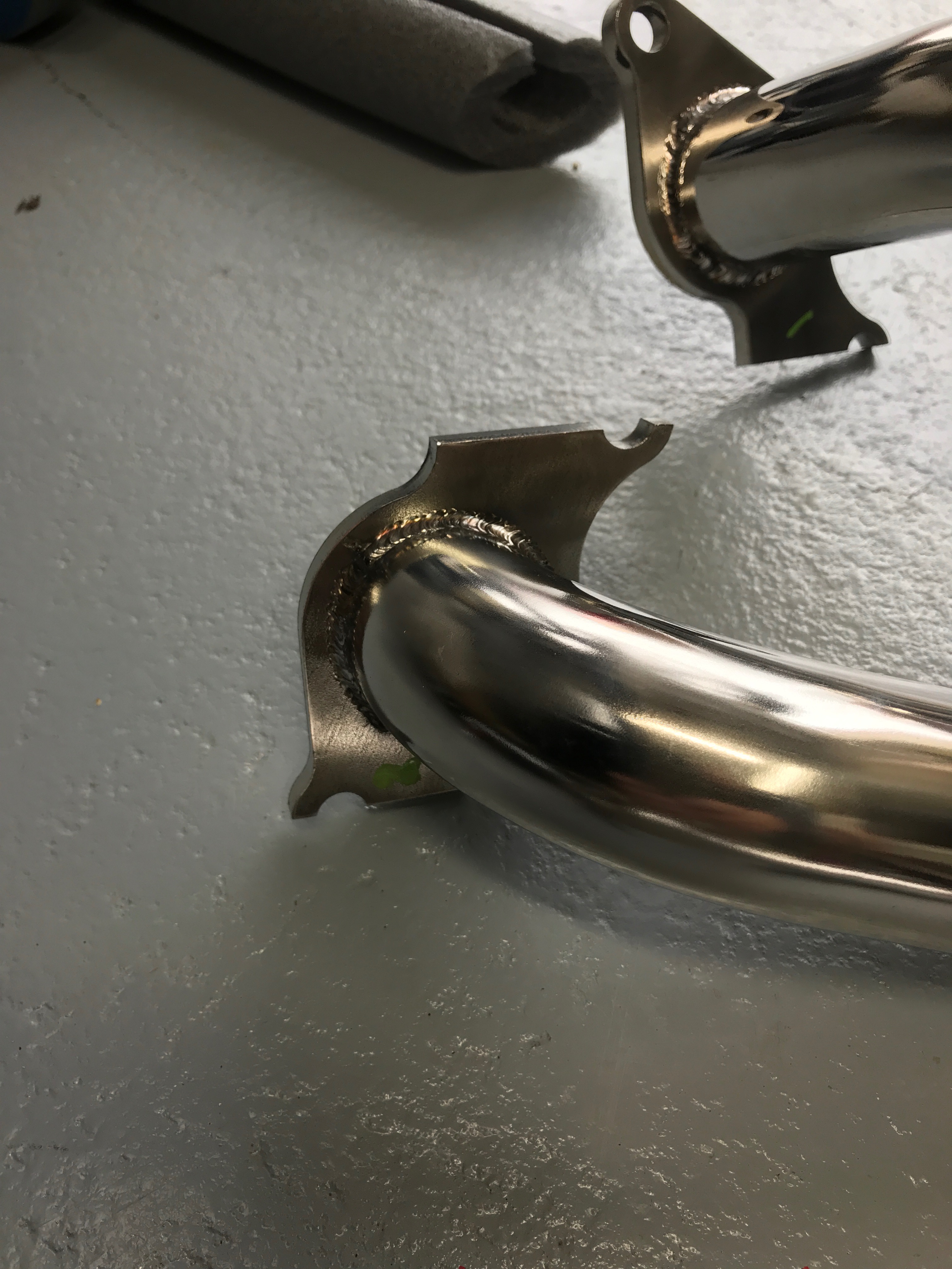
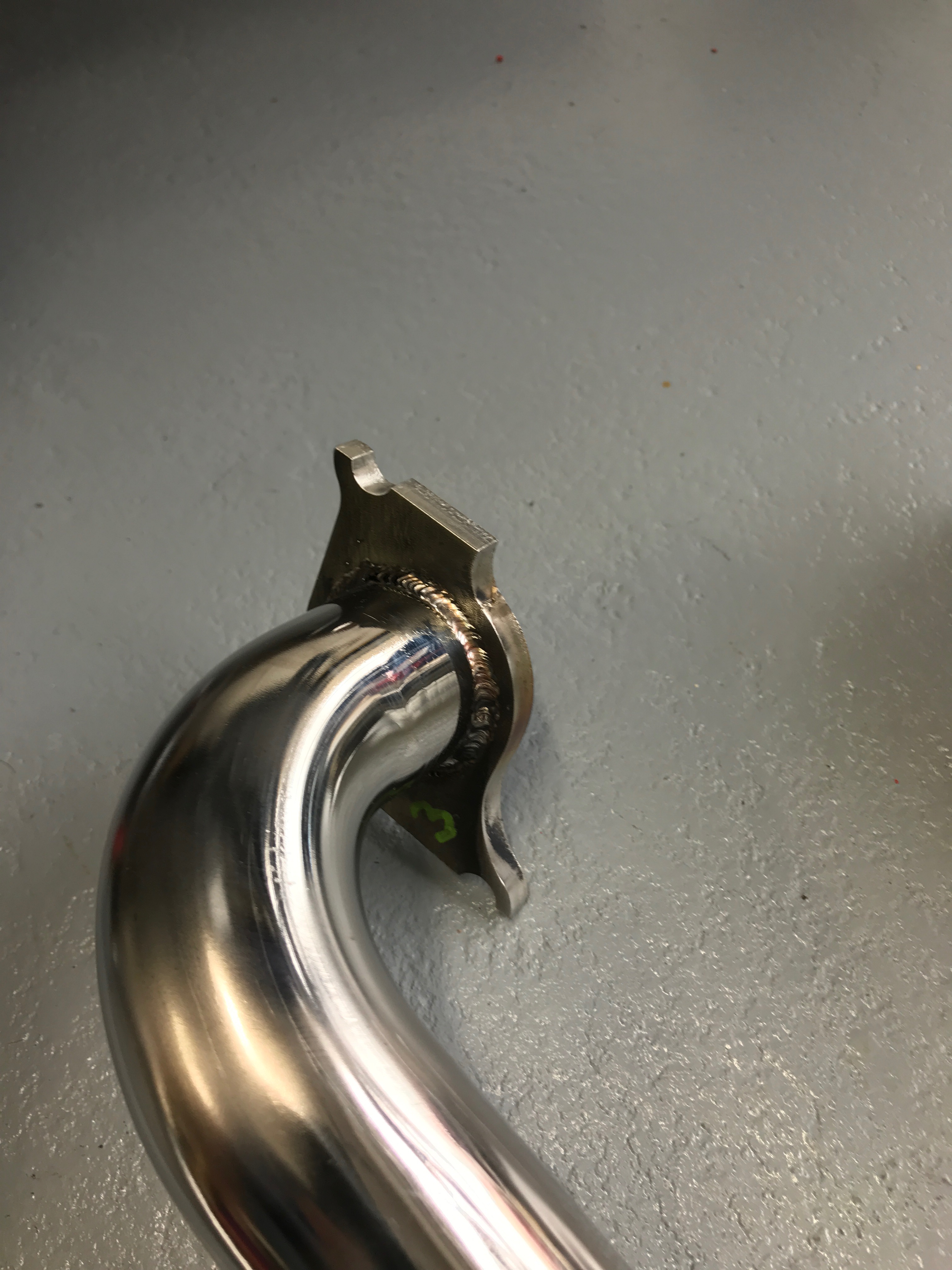
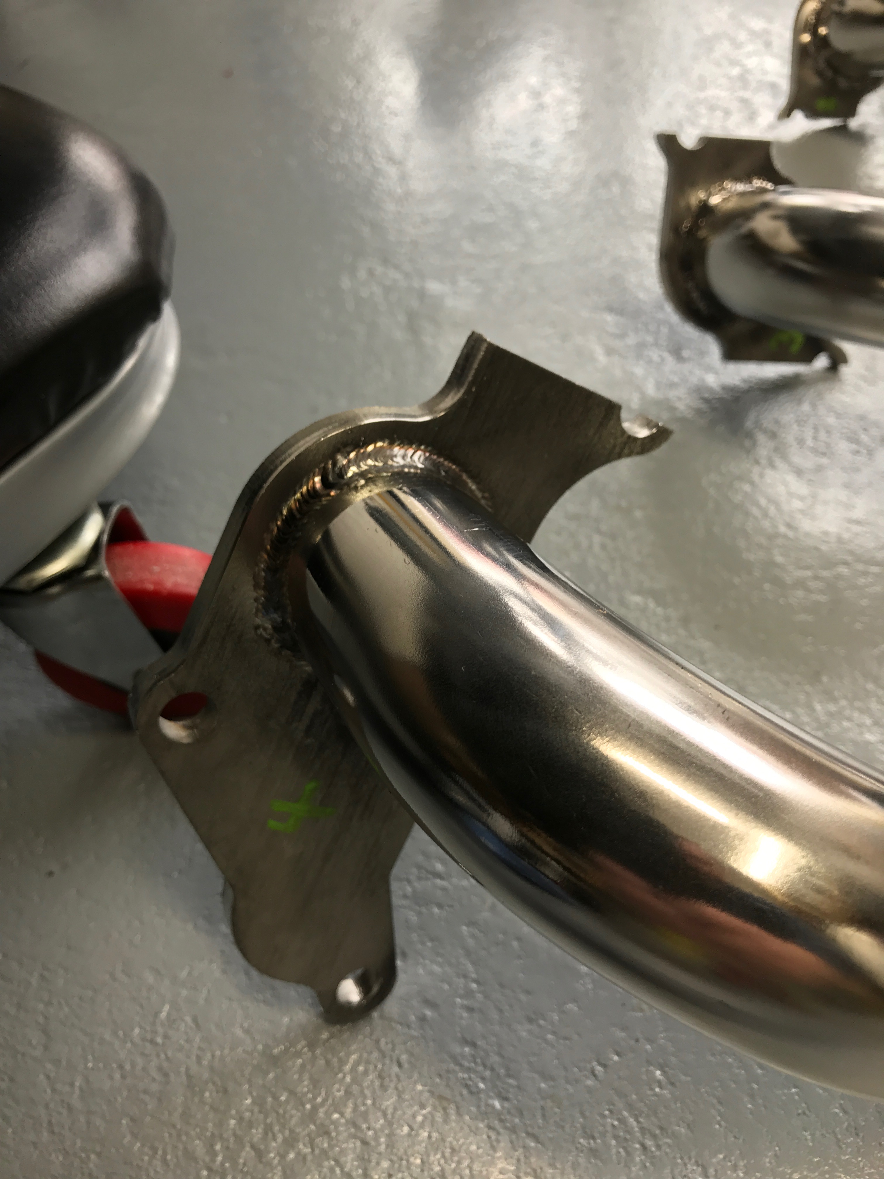
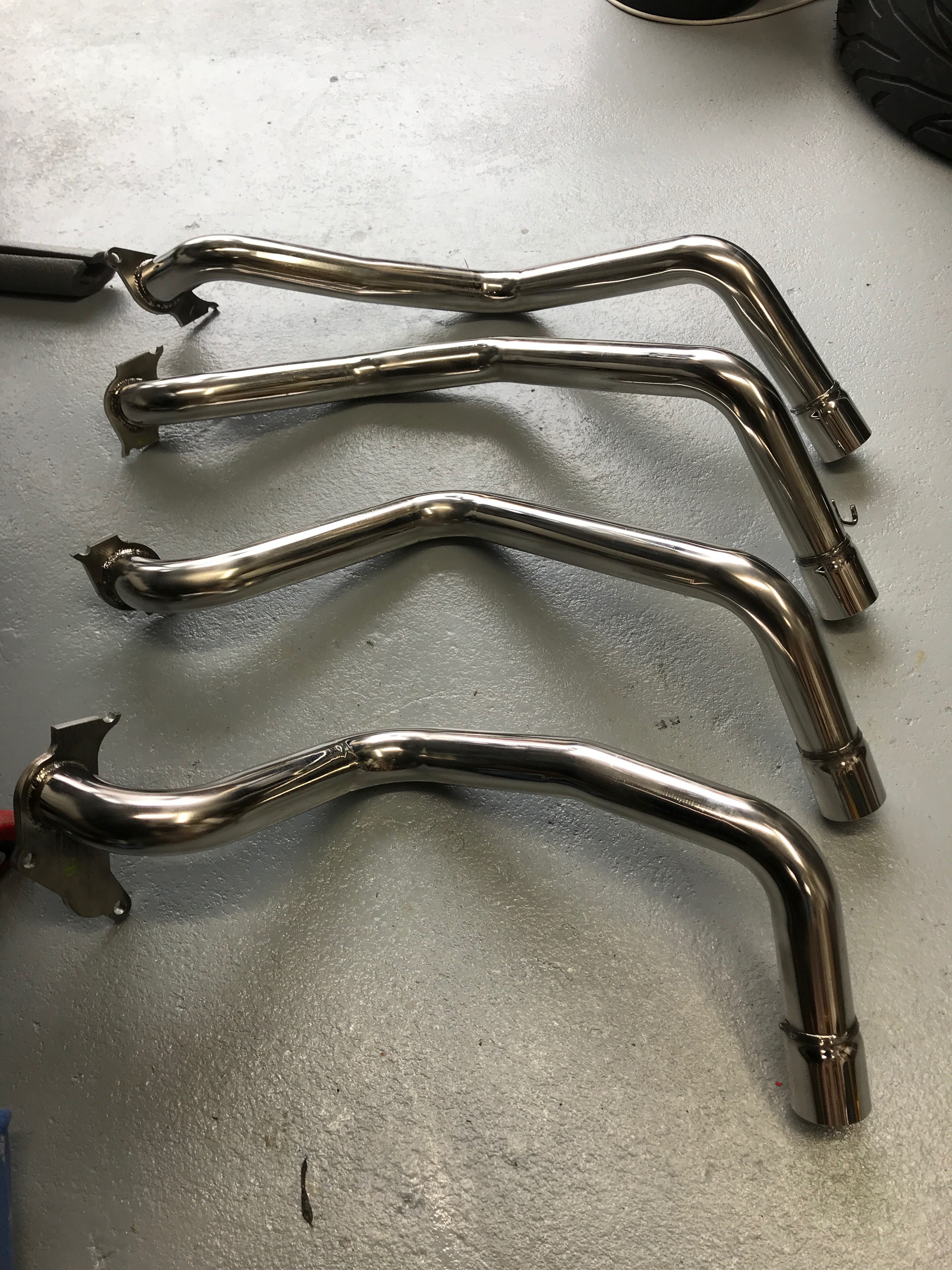
At this point I think I got a bit confused about the numbering that the manual talked about for the primaries. I had to work out which primary goes where… however, it’s totally obvious so not a problem to work out. If nothing else it’s obvious from the pattern of the manifolds and how they make up a jigsaw puzzle to cover the exhaust ports – each primaries’ manifold is a different shape. I numbered the primaries with my green paint pen at this point just so I didn’t have to go back and work this out again.
Next up you feed the primaries either in through the bodywork or out from within the engine bay. I can see how it would be trickier if the steering column is already fitted. I was following the my project plan which is a copy of the order recommended in the manual and so I hadn’t got to the steering column install yet. The order recommended in the manual is working out well at the moment.
I then did up the manifold bolts loosely…

… and made sure the 4:1 end of the cat would fit over the ends of the primaries. Then I tightened up and then torqued the manifold bolts. A couple of them are tricky to get a socket with extension bar onto, you need a wobble joint on the socket extension bar and of course that affects the torque. I tried to factor that in when torquing everything up.
I’m really careful when tightening up cylinder head bolts these days. My first experience of replacing a cast iron manifold on a Triumph Dolomite when I was 15 (35 years ago) taught me to be careful and tighten the bolts up from the centre outwards. I broke two manifolds in 24 hours much to my fathers amusement on the first breakage, and consternation on the second, when he had to go back to a local welder and explain I’d “done it again”.
Of course this head is Aluminium (not Aluminum… that’s not an element it’s a spelling mistake ?) and I’ve also had my fair share of having to helicoil cylinder head bolts on old engines with stripped threads. So I was taking it carefully here!
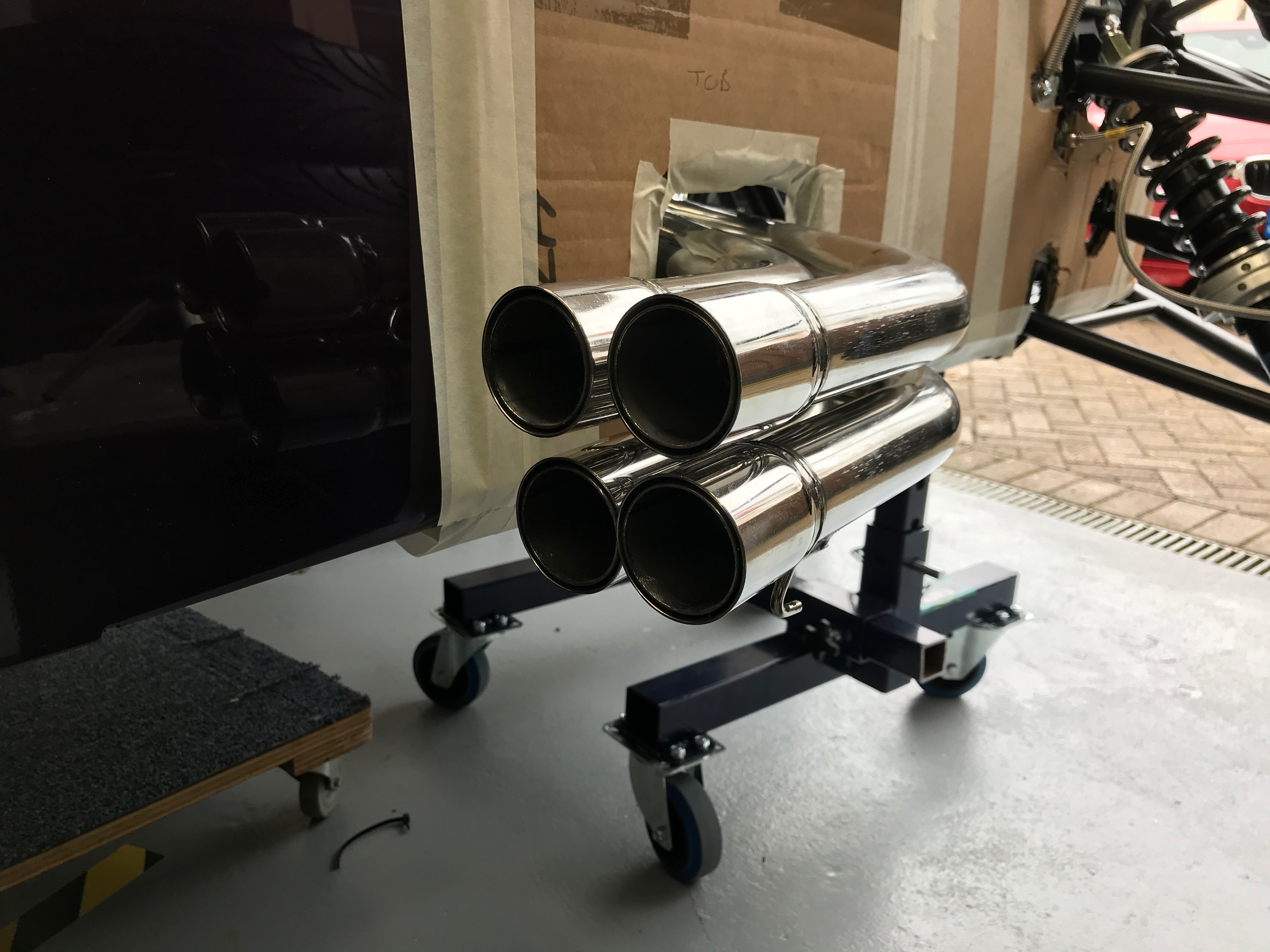
The four primaries create a 2×2 grid of pipes to attach the catalytic converter to.
As the primaries went into the cat I could have used some exhaust sealant at this point, we’ll see if they leak or not later on. It took a fair amount of force to get the primaries into the cat. I resorted to the rubber persuader towards the end of the process but I’m not convinced I got them all the way home. Again, time will tell. Perhaps if I’d got them on further then the next step would have been easier…
The Dreaded Cat Springs
The task here is to attach two reverse springs to keep the primaries attached to the catalytic converters. They’re called reverse springs because when you compress the spring the hooks at the end expand, allowing you to hook the spring assembly over something that needs pulling together.
It wasn’t a difficult job, just time consuming. The trick seems to be to pull the springs into compression with cable ties. As the springs compress they push the arms of the reverse spring assembly outwards, making them wider. This allows them to “slip” over the hooks on the cat and the primaries and then you can release the spring and the assembly tightens.
I used a vice to compress the springs and then two cable ties a right angles across the axis of the spring to get enough even compression.
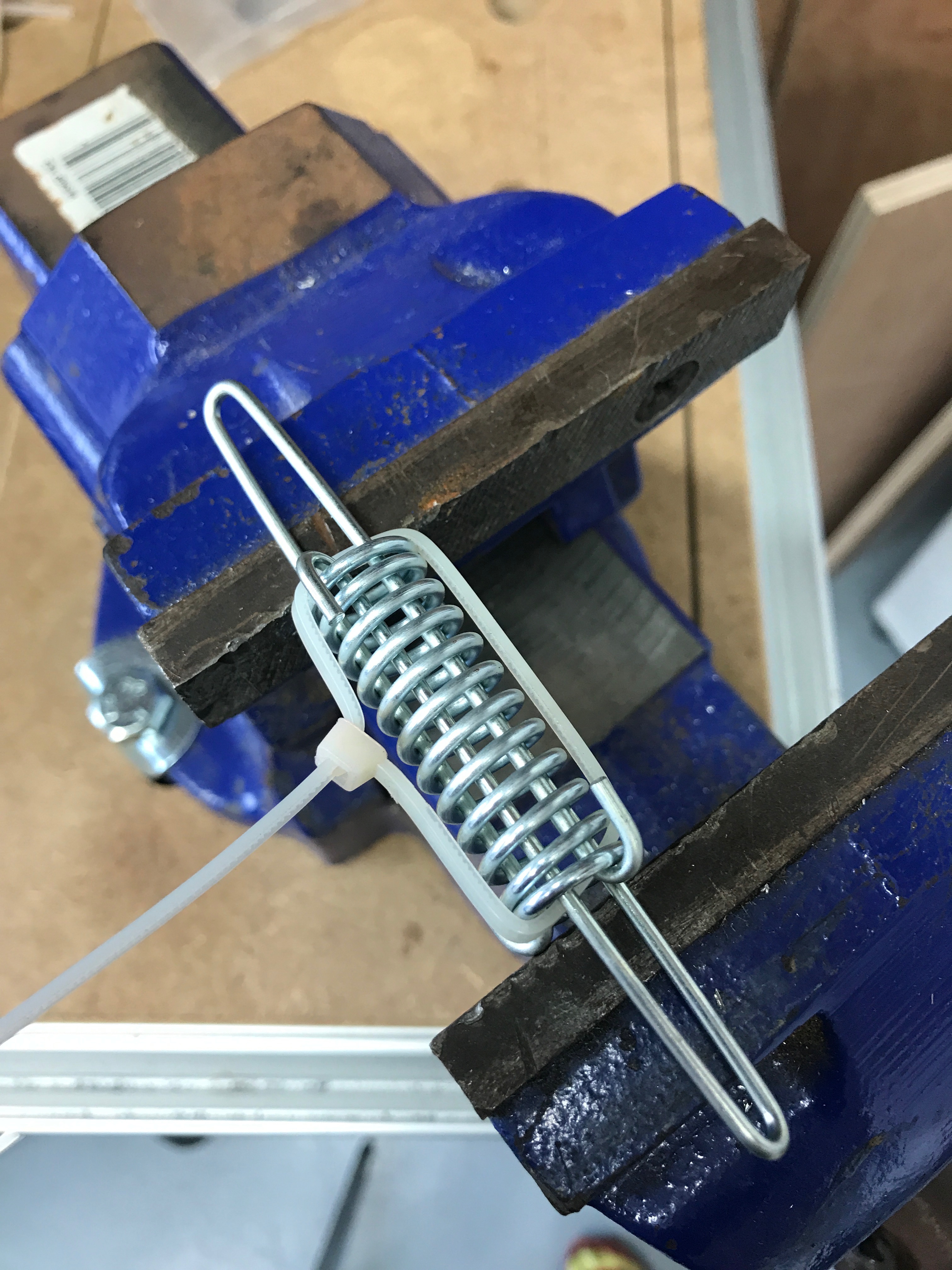
As I said, I think I may not have the primaries fully home in their receivers. I had to compress the reverse springs to their fullest extent and then persuade them onto their hooks with needle nose pliers. As you can see the spring has a long way to go to reach over the hooks on the cat and primaries

I got there in the end but it took longer than I was hoping.

The manual goes on to tell you how to install the rest of the exhaust system but recommends you leave it untill later…. I’m leaving it ’till later.
Lambda Alpha Mu Beta Delta Alpha
Now we had the catalytic converter attached to the primaries it was time to fix the lambda probe, a Rover part.

In principle the probe is a simple job. Screw in the probe, route the cabling and plug it in. The picture in the manual shows the lambda probe’s connection happening on the rail running perpendicular to the length of the car at the end of the driver’s footwell. However, that rail is really exposed to the elements and stuff that’s going to get kicked up underneath the car. Doesn’t seem like a great place to put it. The cable that’s supplied with the lambda probe is also really too long for the connection to make sense there either.
I’d taken pictures of this part of the install when I visited Williams and looked at their factory built 420R. They had run the cable from the cat along the driver’s footwell rail but had made the final connection to the loom inside the engine bay. This makes more sense but I didn’t have a picture of exactly how that connection was made.
Those Williams pictures also showed how the lambda cable gets run along the rail and three rivets used to fix the cable to the chassis rail. Our car came with silver foil tape covering this rail and I wasn’t sure I could rivet into the rail without making a mess.
I was also keen to have some way of being able to replace this cable if I ever get lambda sensor problems. It’s not unknown for lambda sensors to go faulty and I would be drilling out rivets if I went this route.
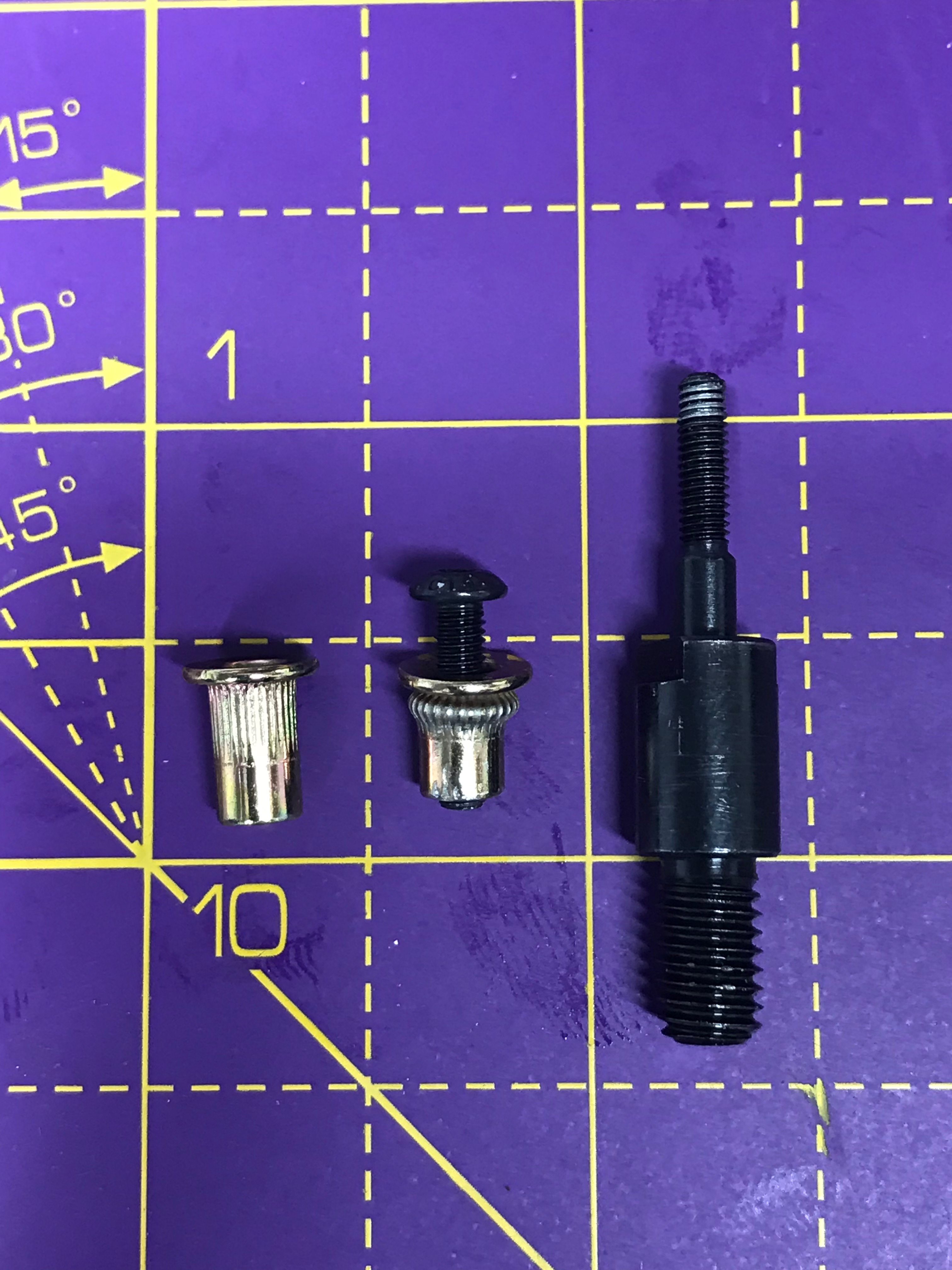
So… rivnuts. I’d not hear of rivnuts before reading the various 7 blogs. For this like me who have not come across them, they are a threaded blind rivet. You drill a regular (though larger) hole, place the rivnut in and pull a threaded mandrel back out creating the bulge behind the original hole. You’re left with a threaded blind rivet.
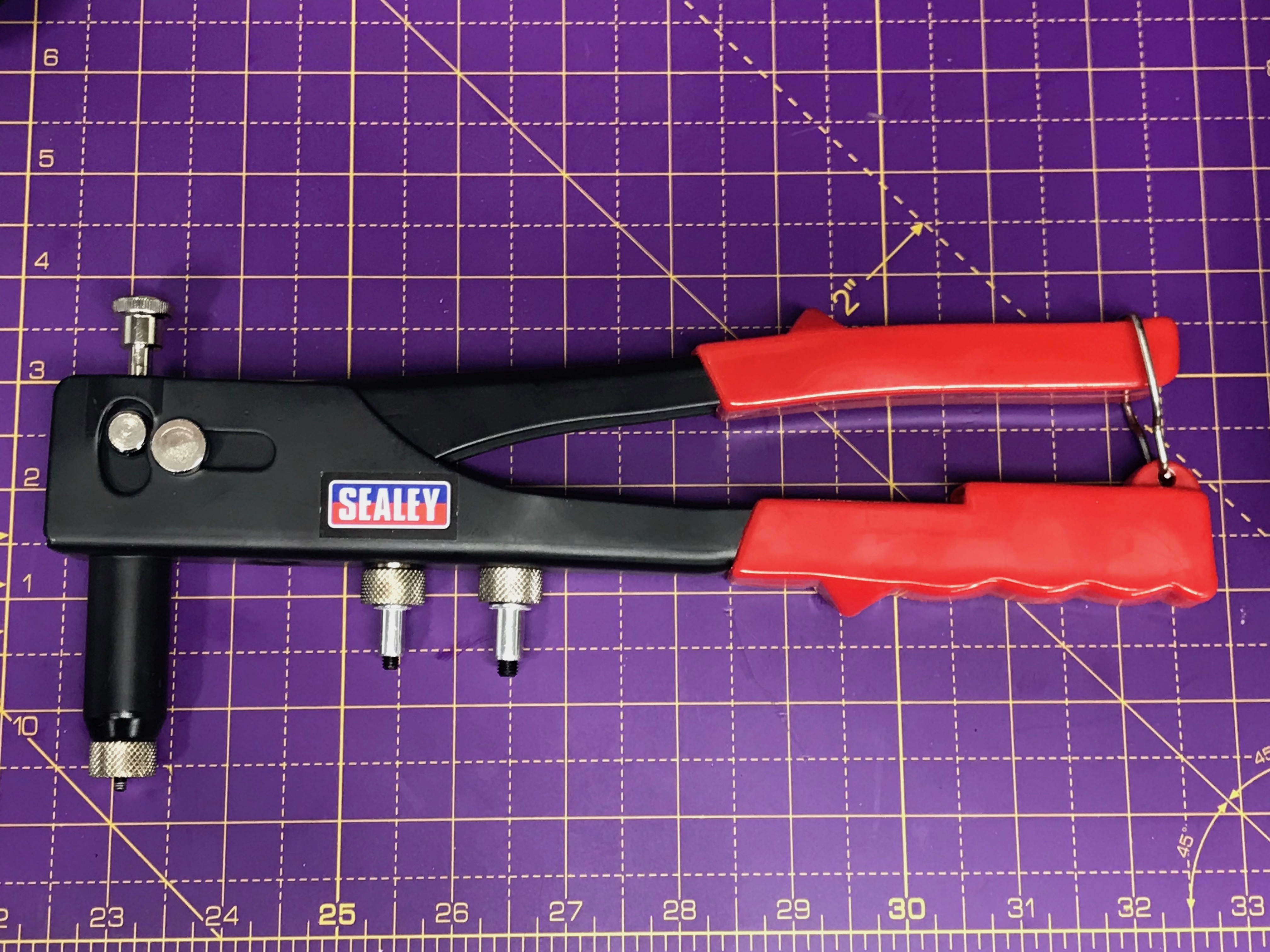
Perhaps this was a bit of a mistake in the end… rivnuts need larger holes than a standard blind rivet and I didn’t want to go crazy with the size of the hole I needed to put into the chassis. So, I went with M3 rivnuts and associated 4mm holes… hmmm… the problem with this size of rivnut is that you tend to pull the mandrel out of the rivnut as you form the fixing in the hole, which of course means you’ve stripped the thread in the rivnut. I’ve tried this a few times now and M3 is just a bit too small. If you couple that problem with the limited space I was trying to work in along the chassis rail… then I really struggled to get 2 of the 3 rivnuts in place securely.
Since working on this part of the build I’ve bought a few more M3 rivnuts from different brands. I theorised that the rivnut walls are too thick for the thread load that M3 can support making the fixing. I thought I might just have a thick brand or batch. However, they all seem to be the same that I bought and they all strip the thread with the mandrel.
Back to the present… I’d also bought some screw mounted cable tie fixings. So the plan is 3 lots of rivnut, screw mounted cable tie fixing and cable tie.
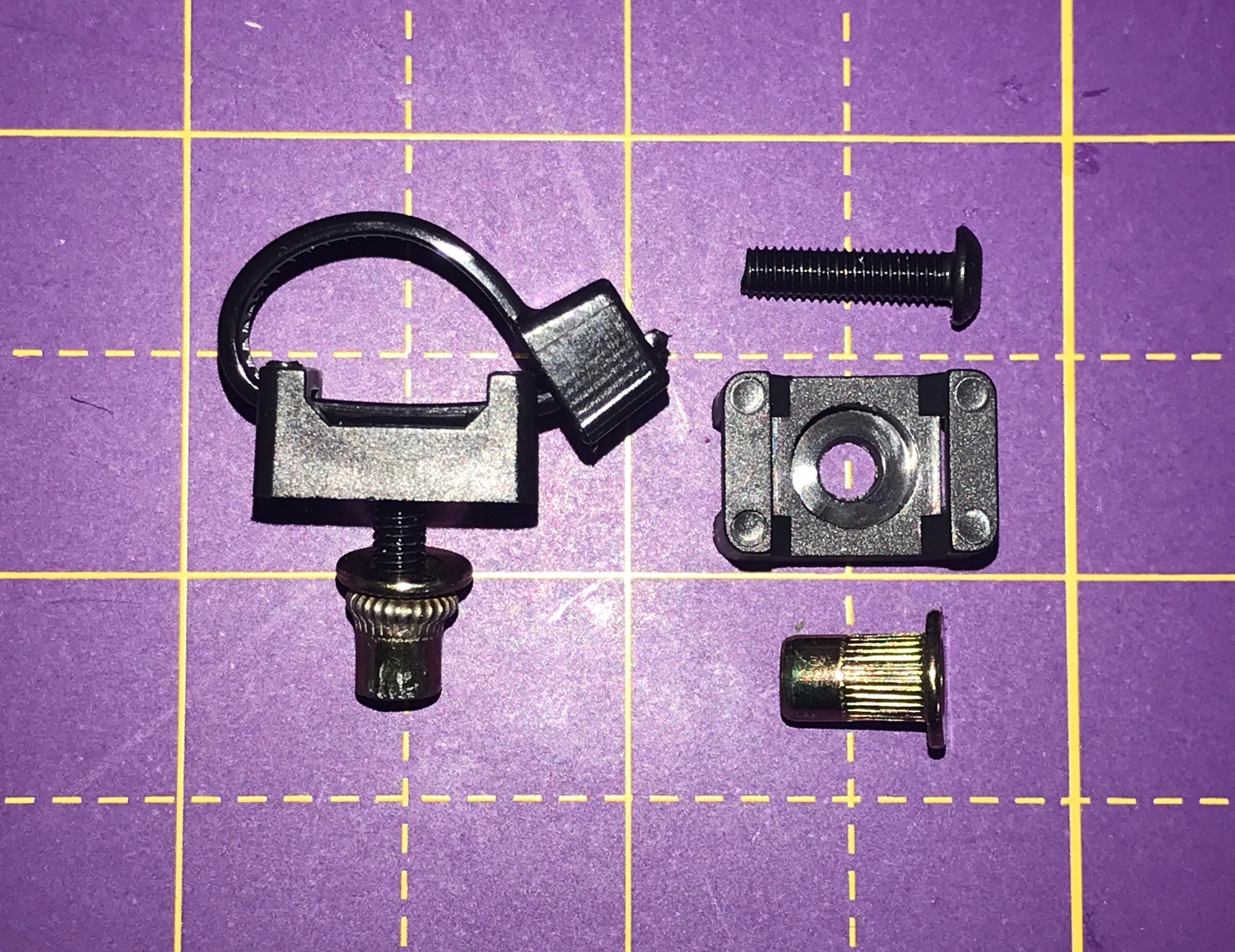
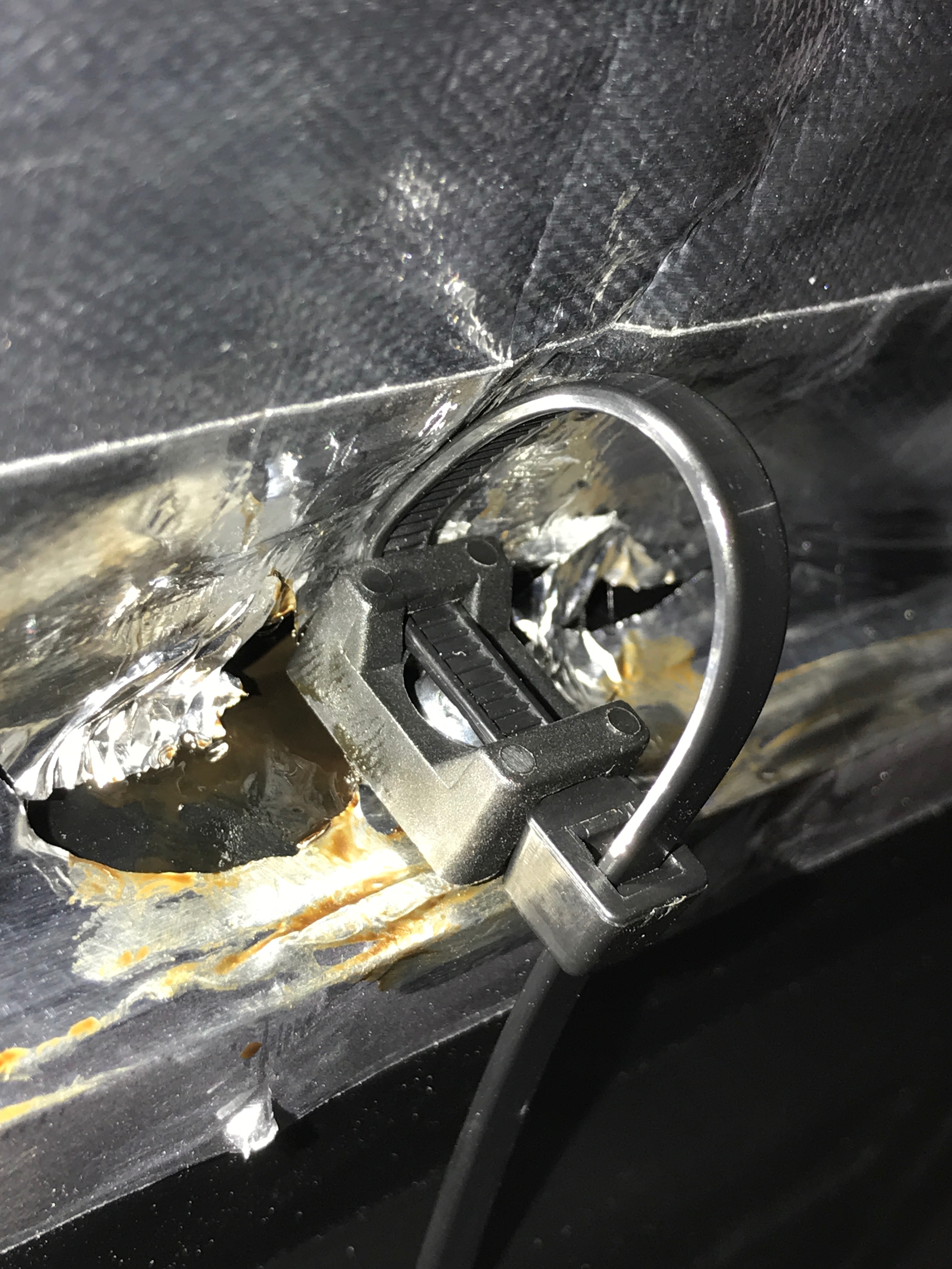
The next problem was that the screw mounted cable tie fixings needed to be rotated into position so that the cable tie ran up/down and not left/right… the lambda probe cable runs left to right on the chassis rail so the cable tie needs to lie top to bottom… but the cable tie can’t be inserted once the cable tie holder is in its final top/bottom orientation – it fouls on the chassis rail. So I had to screw the cable tie holder in so it was almost tight on the rivnut… then put the cable tie in left/right and twist the holder an cable tie through 90 degrees to run the cable tie up/down. Then the lambda cable can run left/right and I could tighten up the cable tie around the cable. Hopefully the image below shows this problem.
[Note from my future self (time travel is possible in blogs apparently): I’ve done a lot more rivnutting since doing the lambda probe and I’m going to revisit these fixing before the project is complete]
I also ended up messing up the aluminium foil on the chassis rail quite a bit. I decided I’d done a good as I could at this point and that I’d either come back and redo the whole arrangement or just tidy up the Aluminium foil with some Aluminium tape I’d got in my tape box.
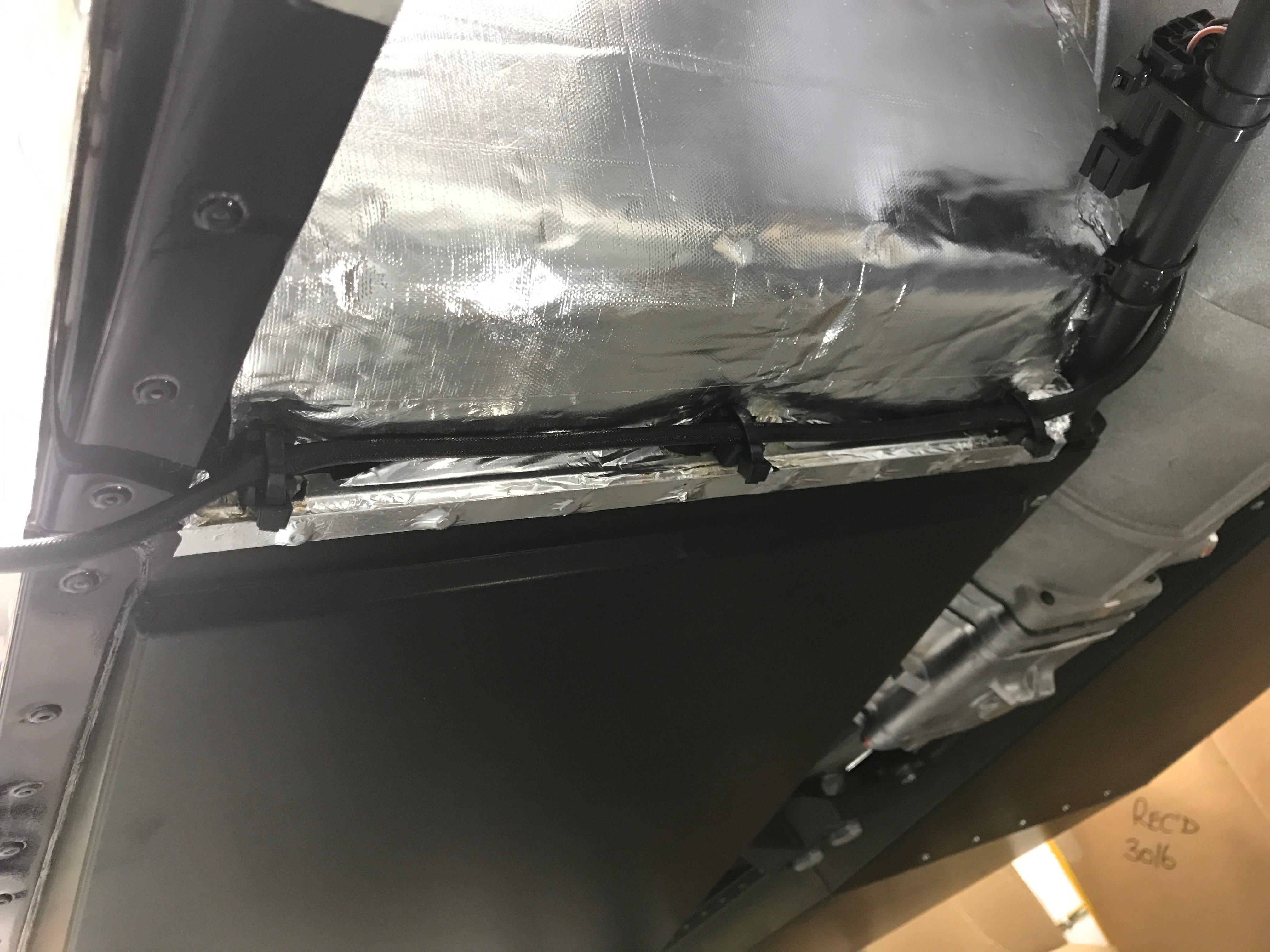
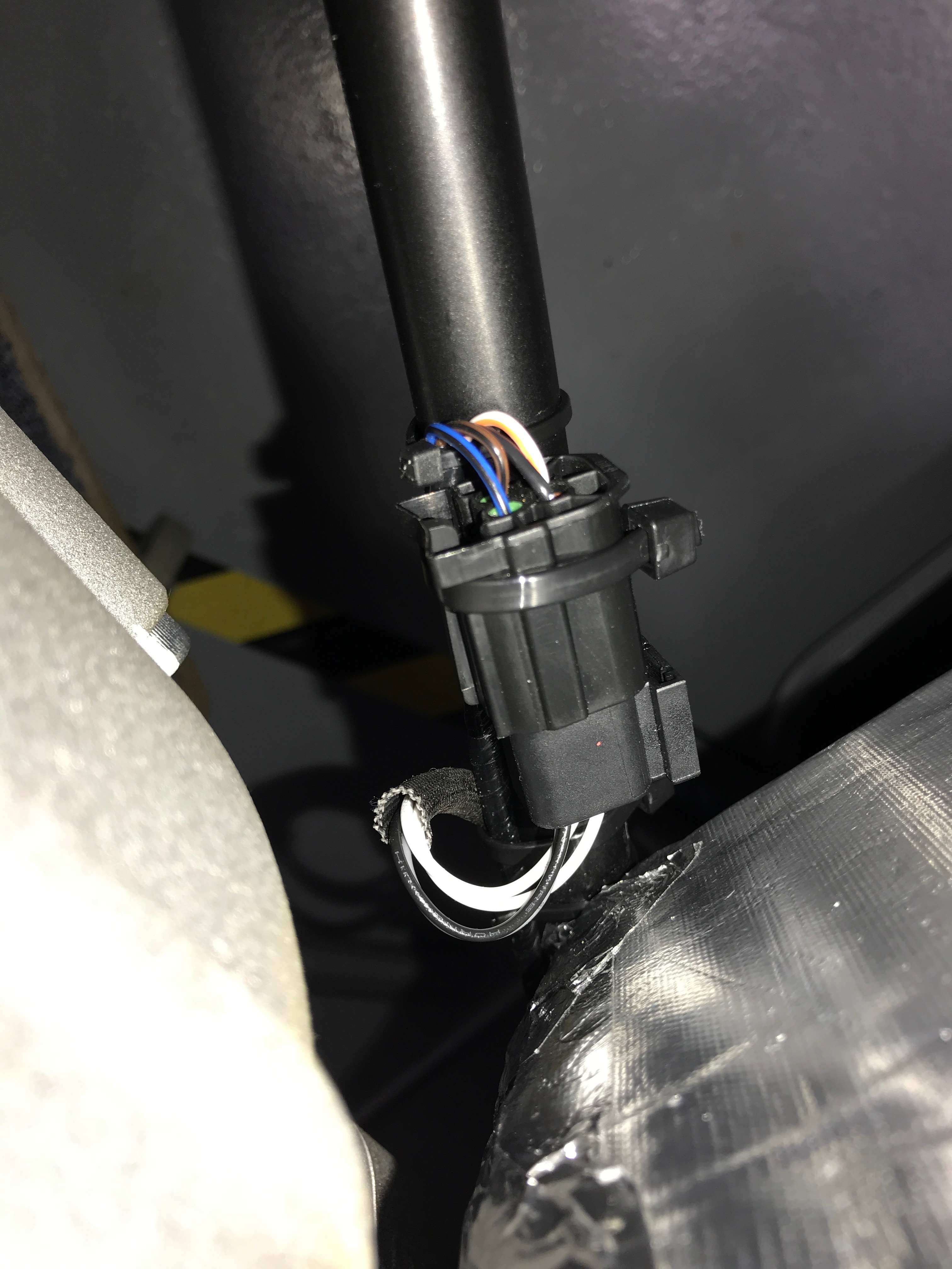
The car comes with the loom side of this lambda probe connection cable tied to the chassis. There’s also quite a lot of cable on this loom side of things.
Initially I thought I was going to have too much cable to be able to make a tidy connection, but eventually I found a way of doubling back all the cabling to make a tidy connection and routing of the cable.
In the end the fixings I put in the chassis are not ideal but the job is done and I can move on.
The car looks great with the polished primaries and catalytic converter in place…


Leave a Comment