

Big day today, big post… we have a whole day (August Bank Holiday Monday) to drop the engine into the chassis. Will it fit? Will the hoist tip over? Will the leveller work? Will my trolleys work? Will my leveller extensions work, or even come loose and drop off? Will I be able to do most of it myself? And more importantly… will it rain?
The weather is set to be dry and sunny all day, we have 4 GoPros and various cameras set up. So, the first jobs of the day are to get the cameras rolling and the car outside.
Getting the Car Outside
I’ve generated a lot of video up to this point but not posted any. So I thought it would be good to get some of today’s video into this post. We’ll see how that works out for people reading these pages but here goes…
At some point I hope to get some videos of the more interesting parts of the build up onto YouTube. There’ll be a link here in the future if that happens.
Back to the build…
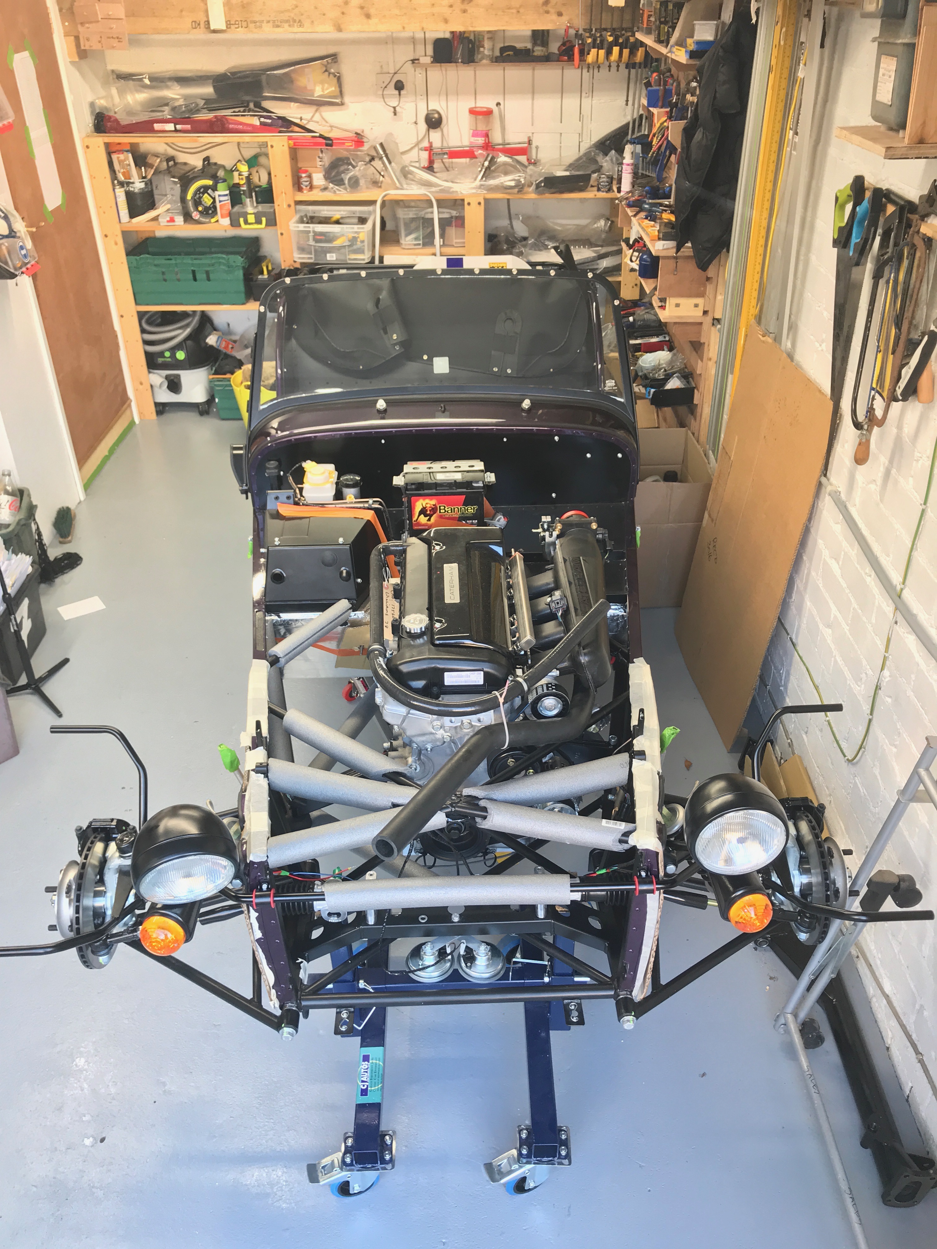
Moving the car around like this is where the wheeled axel stands are really paying off. I’d have struggled for head room on the hoist with the car in the garage. Having the extra space around the sides with it out in the open helped us be more careful around the bodywork. I’m not sure it helped in the time it took to get the engine in, but I felt a lot better having the extra freedom to move around and with more people around the car to help.
Engine prep: Off come the Alternator and Engine Mount Struts
Next up there was a little more prep required on the engine. In order to stand any chance of getting the engine into the car it’s advised that at least the alternator gets removed.
I’ve also seen it recommended to remove the engine mount struts.
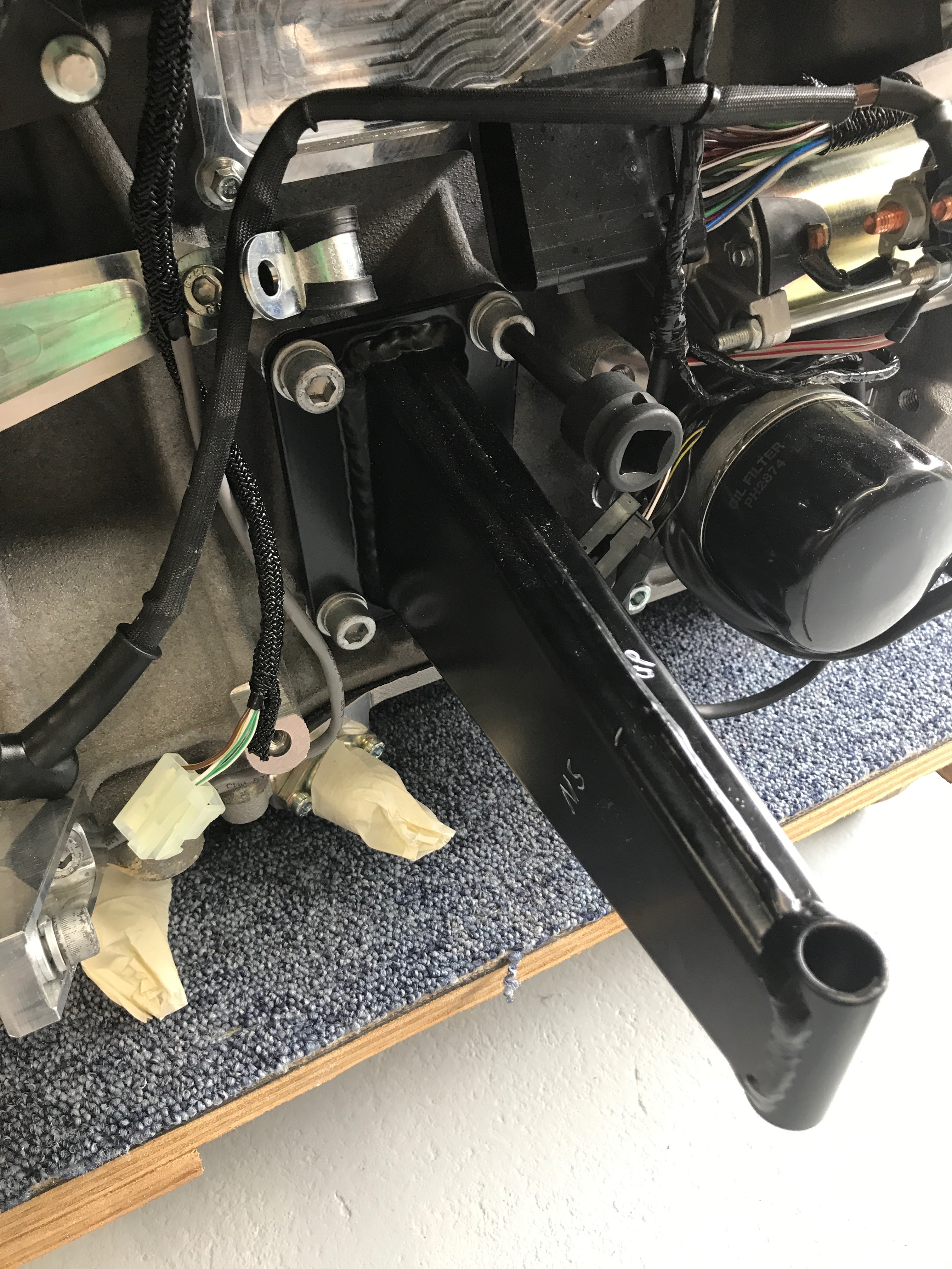
As you can see in the image above, I’d written in white paint which way up and from which side each of the struts had come from. Which side is simple, one side has three bolts and the other has four – I spotted that as I painted up the second strut! I also made sure I stored the bolts in the threads they’d come from, so that I didn’t put a strut back on in the wrong configuration. There are a number of unused threaded holes in the engine block and I didn’t want the added confusion of wondering later, with the engine hanging in the bay, why the struts didn’t line up with the engine mounts. Maybe its not even possible to put a strut back on in the wrong place, but I didn’t want to test that theory this time around.
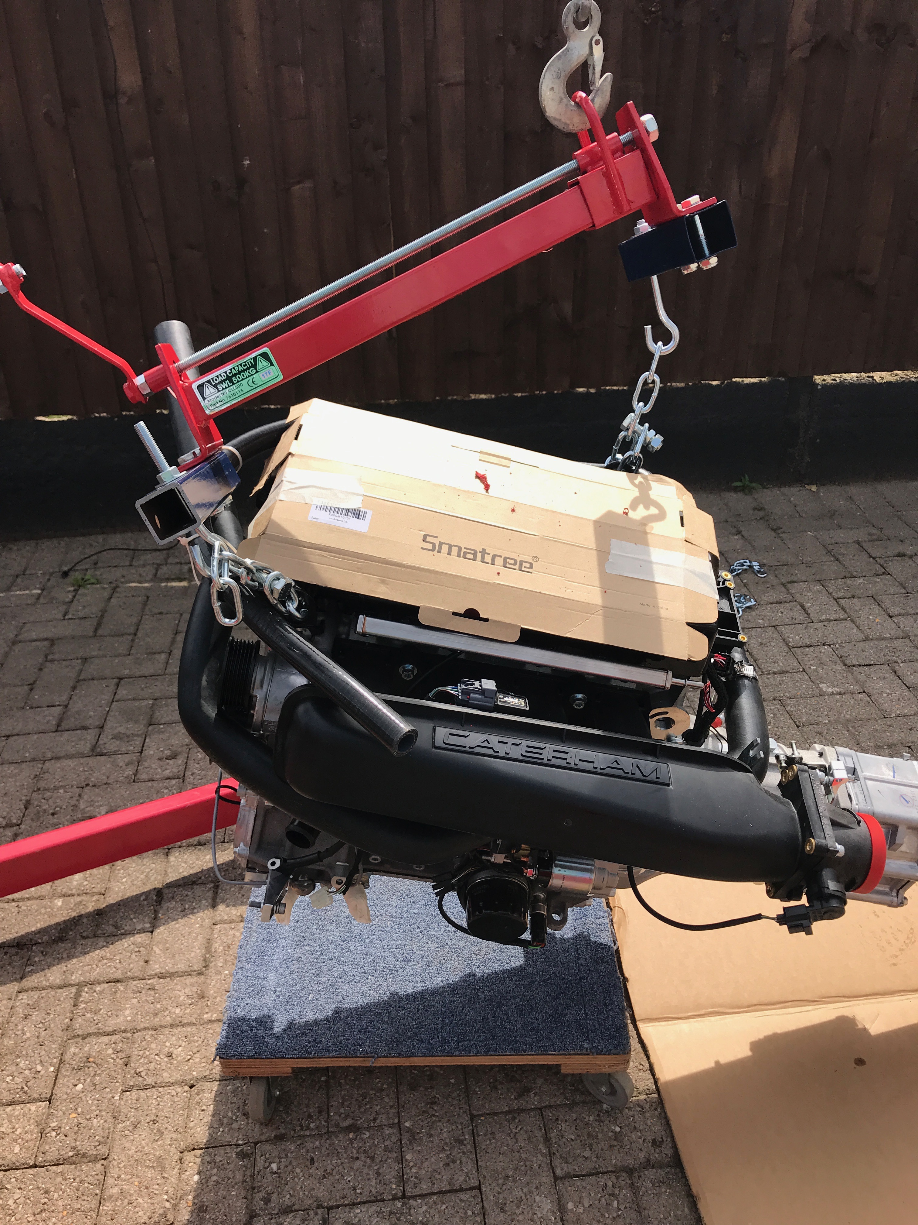
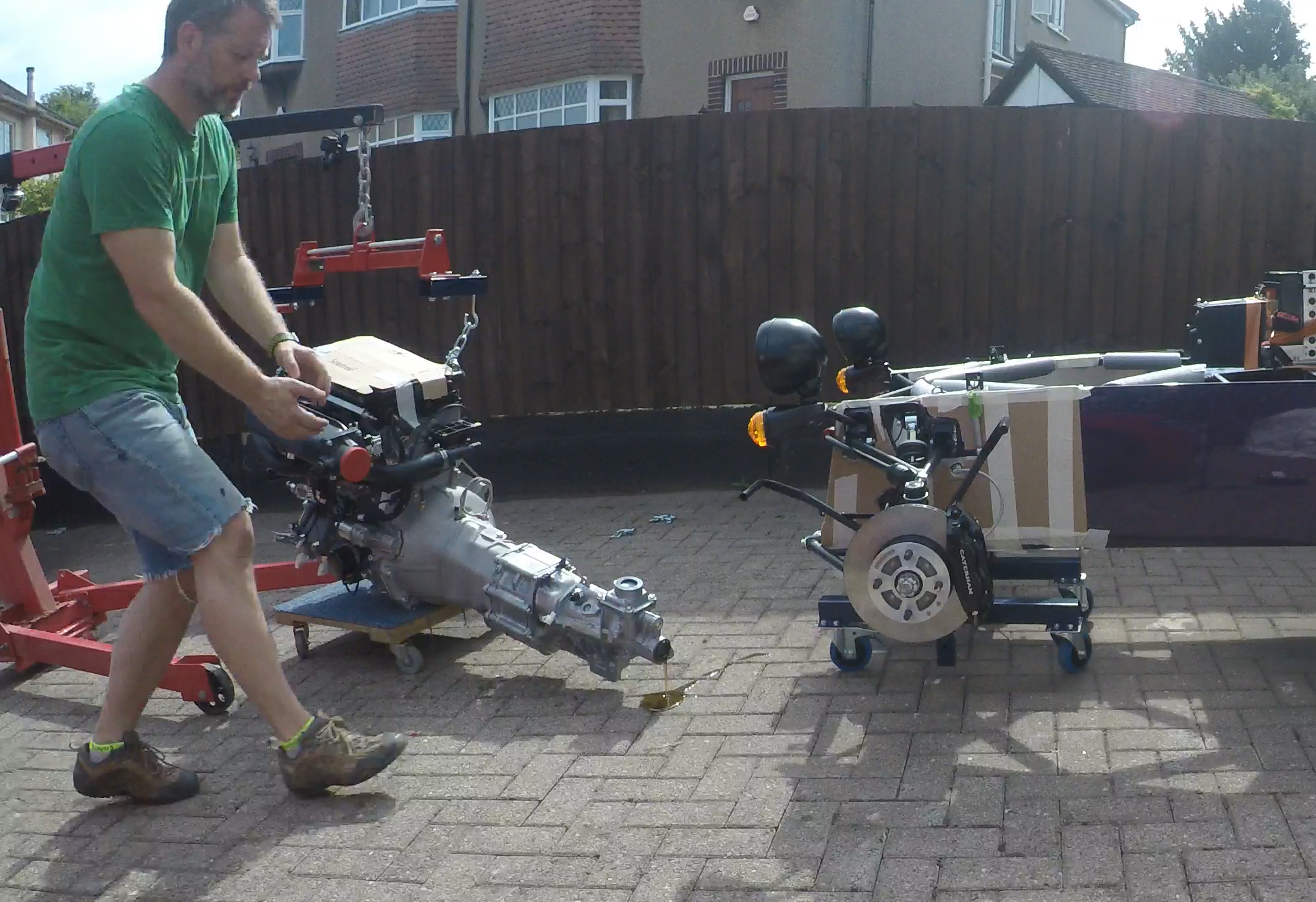
Out Comes the Engine
Getting closer… rolling the engine outside…
Again, having the engine on my homemade trolley was really useful. Especially at this point… but I’d also had to shift it around the garage a couple of times and doing so without this trolley probably wouldn’t have been possible without my own hoist. Handmade trolley for engine/gearbox… highly recommended!
Footwell Protection
As well as the pipe lagging I’d installed onto the chassis rails, it’s also advised to protect the footwells and specifically the reflective heat protection covering them. The protective padding also runs down the transmission tunnel and I added cardboard to anywhere I thought could get banged up if a 100Kg pendulum hit it. The cardboard’s not going to protect against a big impact but it would stop the padding from being ripped if the engine grazed it on the way past.
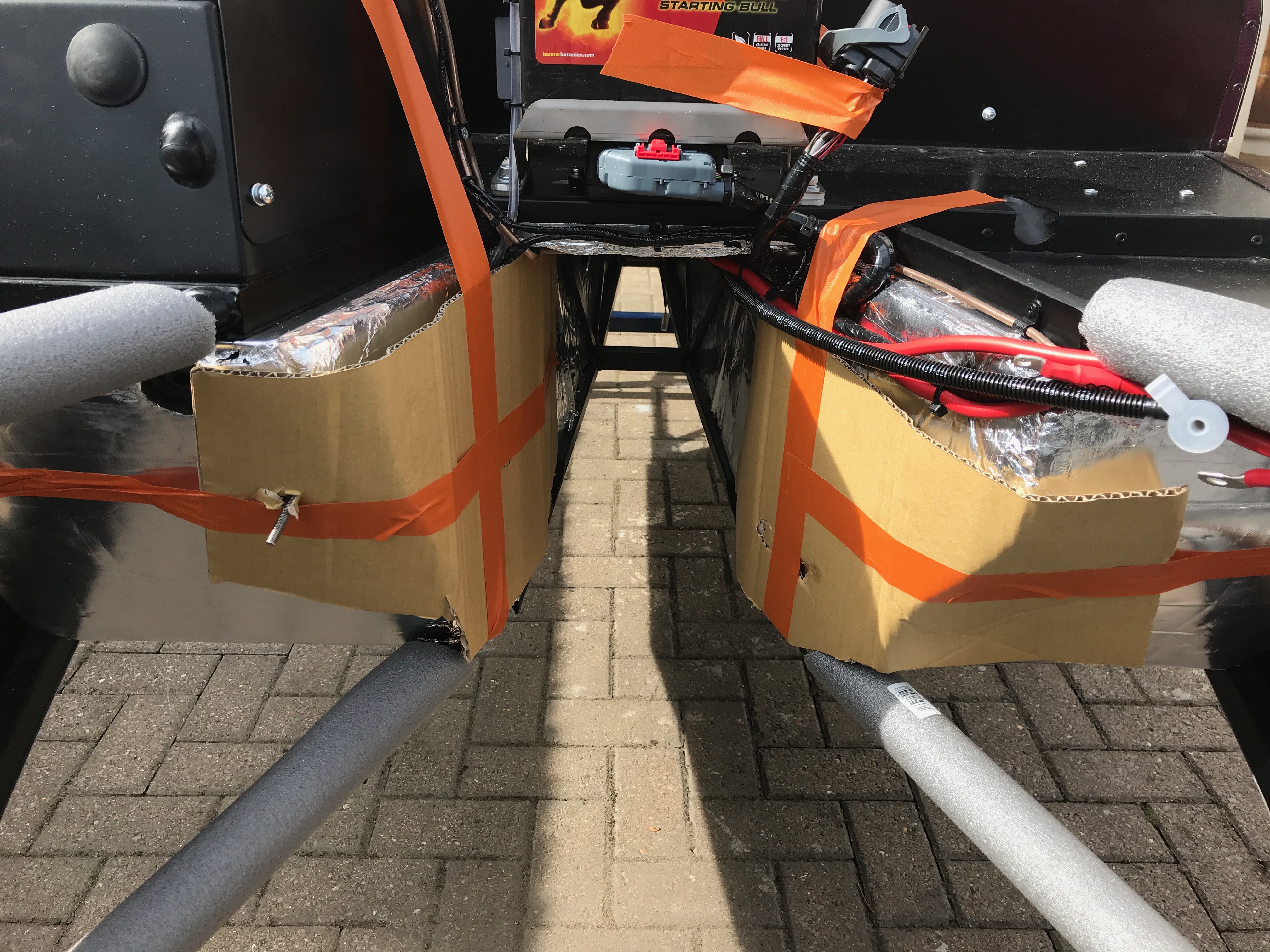
… and from a wider angle…
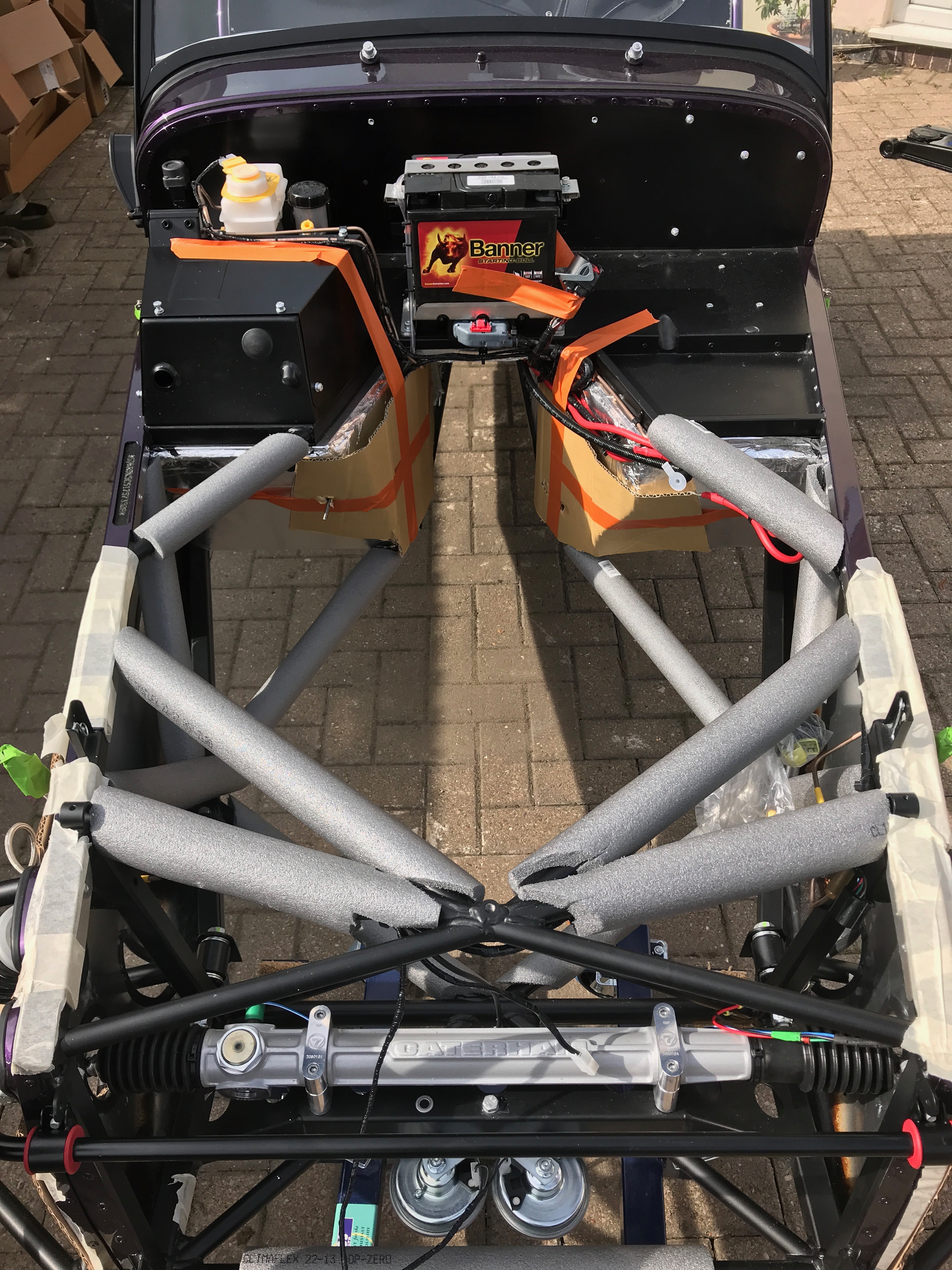
Lowering the Front of the Car
Finally the last task before attaching the engine to the hoist was to drop the front of the car on its stands. The engine has to go into the car at around a 30° angle – or at least that’s what we did. To steal another few degrees its recommended that you drop the body to the lowest setting of your axel stands. And so that’s what we did…
I think this gave us about an extra 5°.
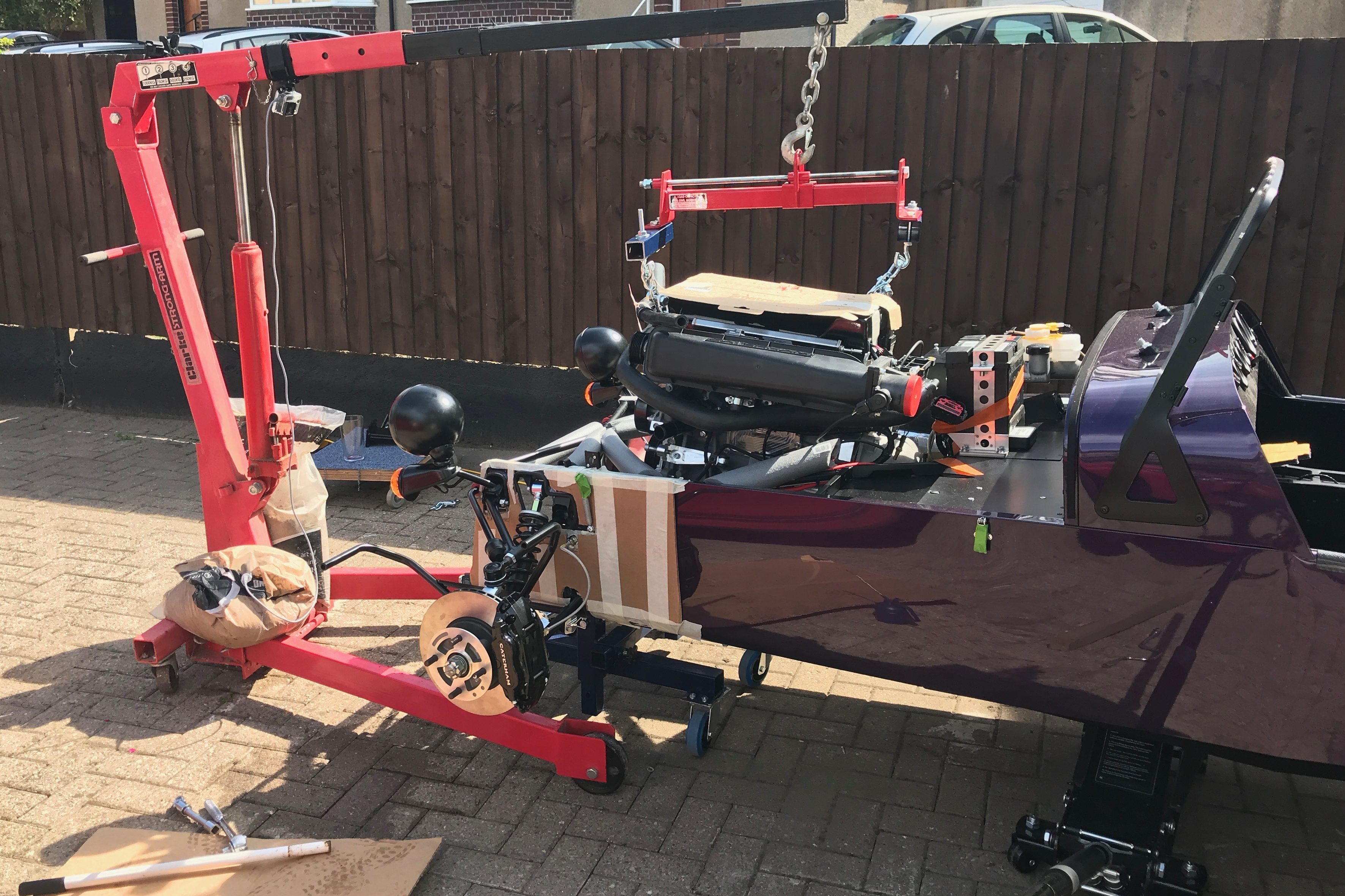
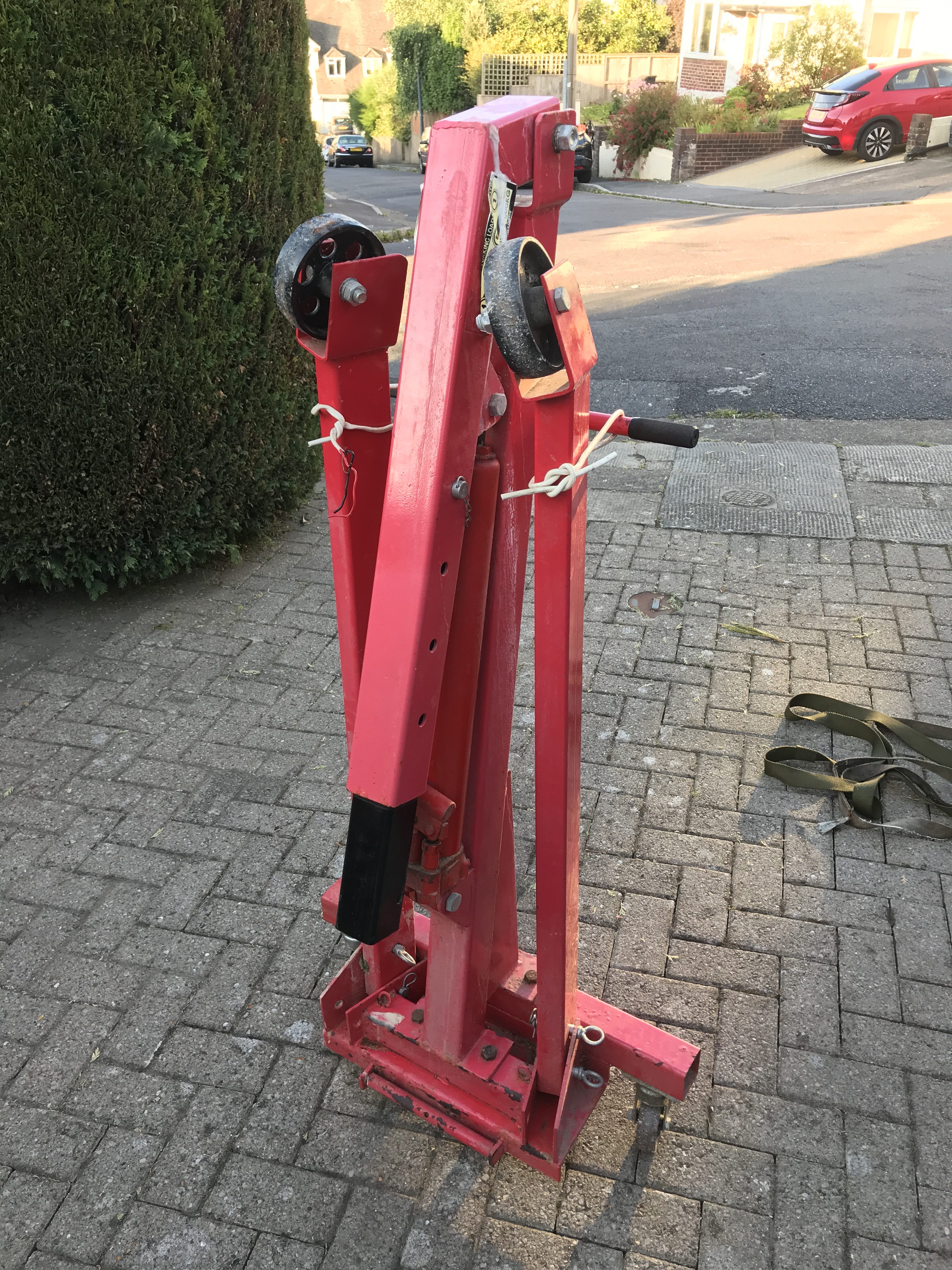
Setting up the Hoist
Ok, so this part didn’t go to plan. I thought I’d got my head around how the leveller worked. But once it was dangling from the hoist and with the engine below it, it wasn’t obvious what was making the engine tilt and how it worked. But more of that later…
There was also the small matter of the hoist tipping when the engine and gearbox were lifted. While the whole arrangement stayed upright, it didn’t take much downward pressure at the engine to tip the whole thing forwards. I’d have thought only about 5Kg of weight (50N) was enough to tip the rig.
We definitely needed to add some ballast. It was definitely going to tip as we moved the hoist over the pavers and put pressure on the rig as we operated the leveller and jiggled the engine around the chassis.
The solution was simple… a couple of bags of aggregate/sand… and for a while we also had Ted standing on the back of the hoist as ballast while we found the aggregate bags!
With the rig now properly stable we had various attempts at moving the leveller one way and then the other until we got the hang of it. If I’d have thought about it some more when I was making my outriggers I’d have made them so they shifted the leveller backwards on the engine and moved the COG closer to the middle of the leveller.
I also played around with the length of the chains attaching the leveller to the engine. I tried a few configurations but in the end I left them both about the same length.
In the end I did get the leveller to work within a good range of its screw thread. As you can see from the picture above… as the leveller centre hoop (attached to the hoist) moves left (towards the front of the engine) you can think that its pushing the rest of the hoist and engine to the right, therefore, dropping the gearbox.
Watch out for the Oil Slick
It was about at this time that I realized I’d made a schoolboy error. I’m sure the manual talks about removing the plastic plug from the back of the gearbox prior to the engine going in. I duely did this only to find that once the engine was inclined to somewhere close to the angle I wanted to try and drop it into the car, all the oil from the gearstick reservoir drained out of the hole where the plug was – the hole where the prop shaft goes.
I quickly put the plug back in, placed some cardboard under the engine and hoist (in case the plug didn’t hold as it was all tipped again), and had another go.
Finally we got the hoist somewhere close to what we needed. I’m not sure the leveller extensions did a great deal to remove the twist but I think we were better off with them than not having them. The engine was still twisted a few degrees clockwise (when looking from front of car) but in the end we didn’t have to worry about the rotation as it seemed to correct itself once the gearbox was supported on the trolley jack.
All told I probably played around with the hoist for and hour or so. It was then that I was joined by Ted, from next door, Harry and Sue. We then had another go at getting the engine lifted and set at the right angle to go into the car.
We were ready to go…
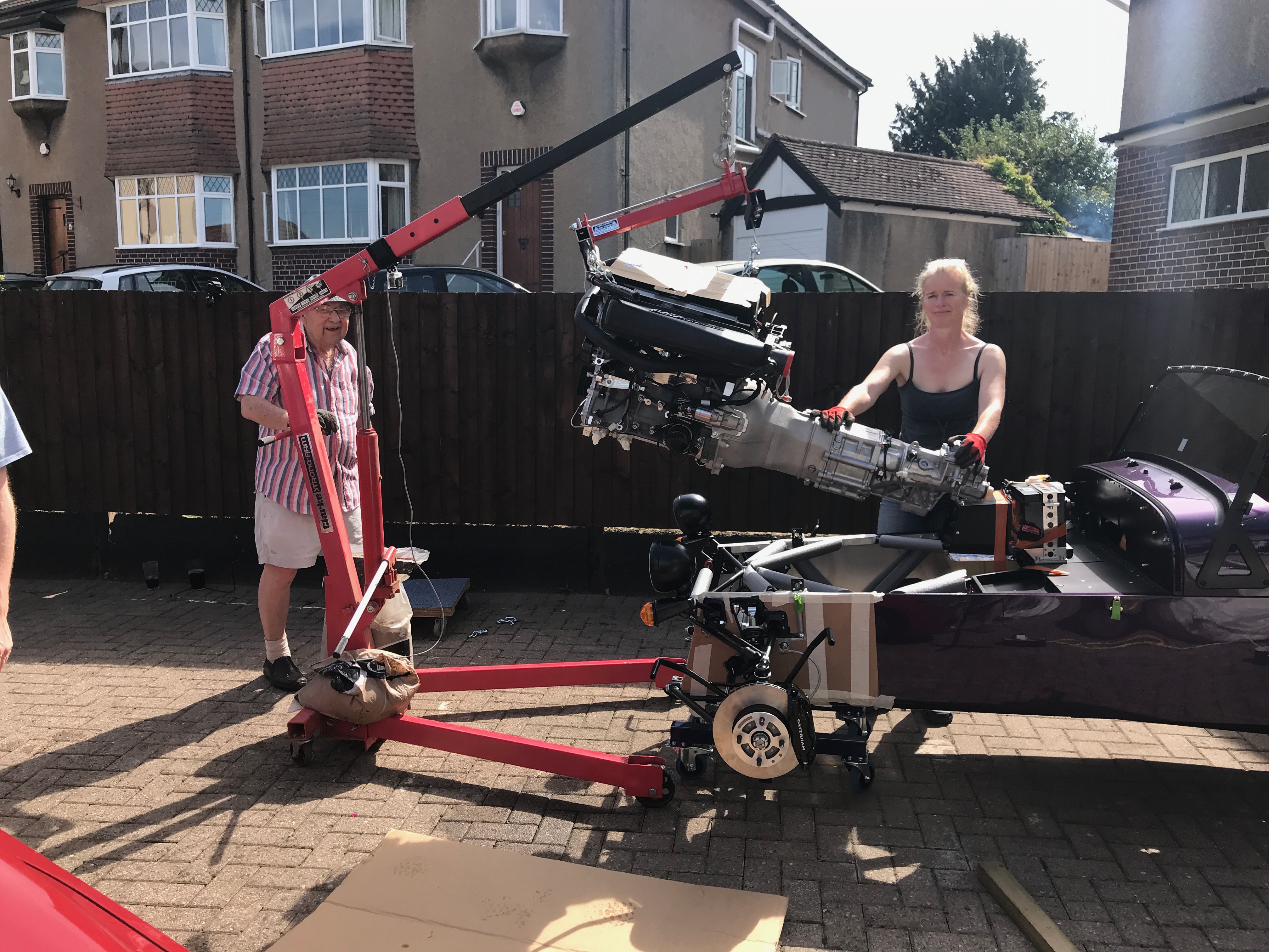
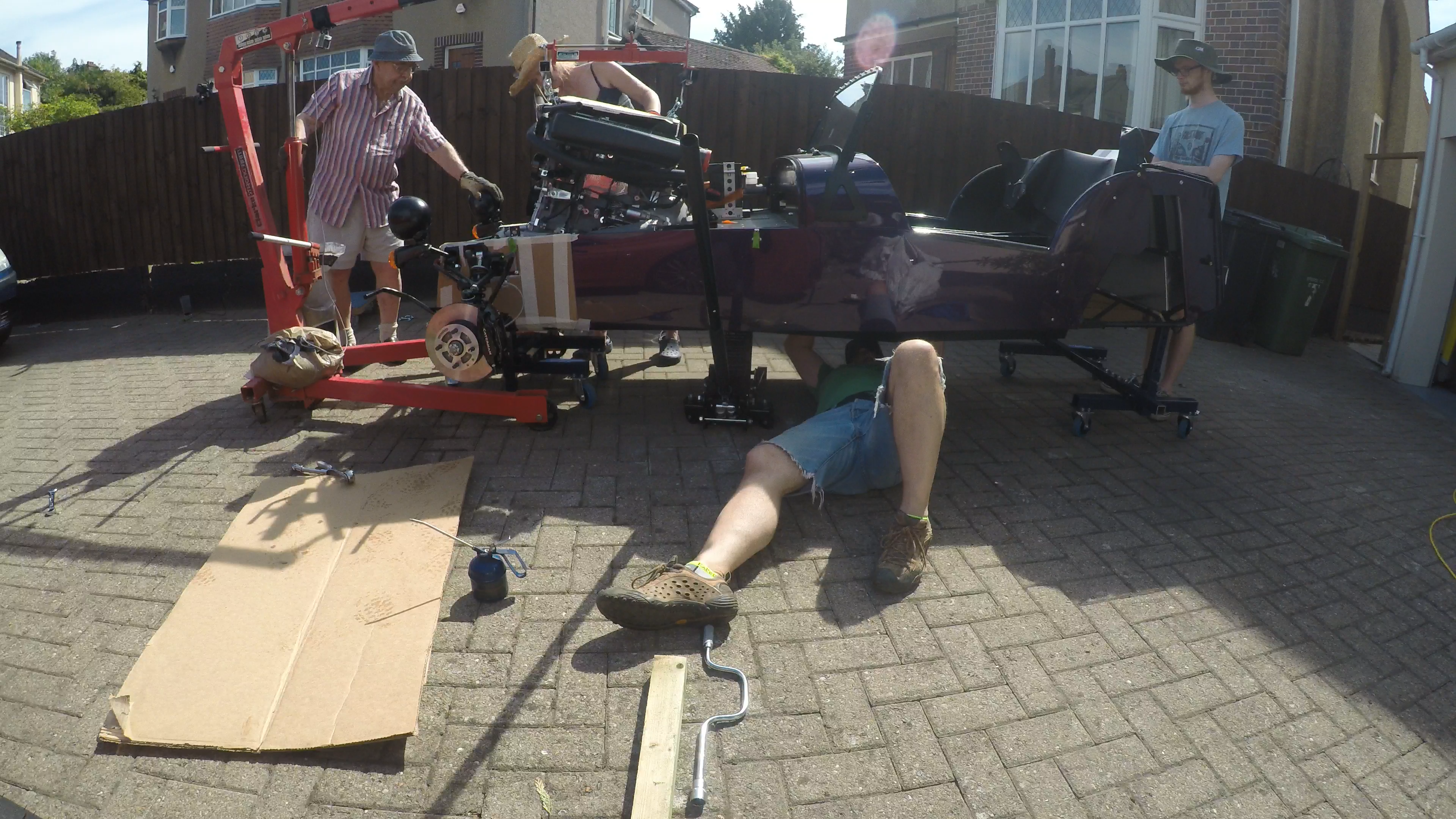
Engine Two Step
We then spent a couple hours (plus a lunch break) doing the engine, gearbox, hoist, leveller and car two-step. As others have described, its a case of a few centimeters forwards, a few centimeters down, a few centimeters forward, a few centimeters down, etc etc.
Here’s some video of us getting the engine to the right angle and then dropping it the first bit of the way (at some point I’ll edit all the engine install video together for a YouTube clip)…
One difference we had from many of the blogs I’ve read is that we were able to add another dimension to the dance. Because of the wheeled axel stands, we were able to move the car instead of the engine and hoist. The wheels on the hoist were steel and rattled and caught on the pavers we have for a driveway. The wheels on the axel stands were my swapped out synthetic wheels and they rolled much better on the pavers. This meant we could be much more accurate in moving the car than moving the hoist. Each jiggle forwards and down could be much more precise.
Once we had the gearbox roughly inside the opening of the transmission tunnel we could introduce the trolley jack to the equation.
As the gearbox was fed into the transmission tunnel we supported that end of the assembly with our trolley jack. It supported the gearbox but also seemed to straighten out the twist of the engine caused by leveller being oriented off the centre line of the gearbox and engine assembly (as discussed in yesterday’s post).
We got most of the way there before lunch beckoned…
Lunch was done and I got back into the mid-afternoon sun…
The only really tight part of the process was the point where the front of the engine passes the LHS front diagonal chassis member. In the end we had to remove the pipe lagging and replace it with a piece of cardboard to protect the chassis. The engine then passed the chassis member by a few millimetres. Just when we thought it wouldn’t go any further we could either go down or back a few millimetres which would then allow us to move in the other axis again.
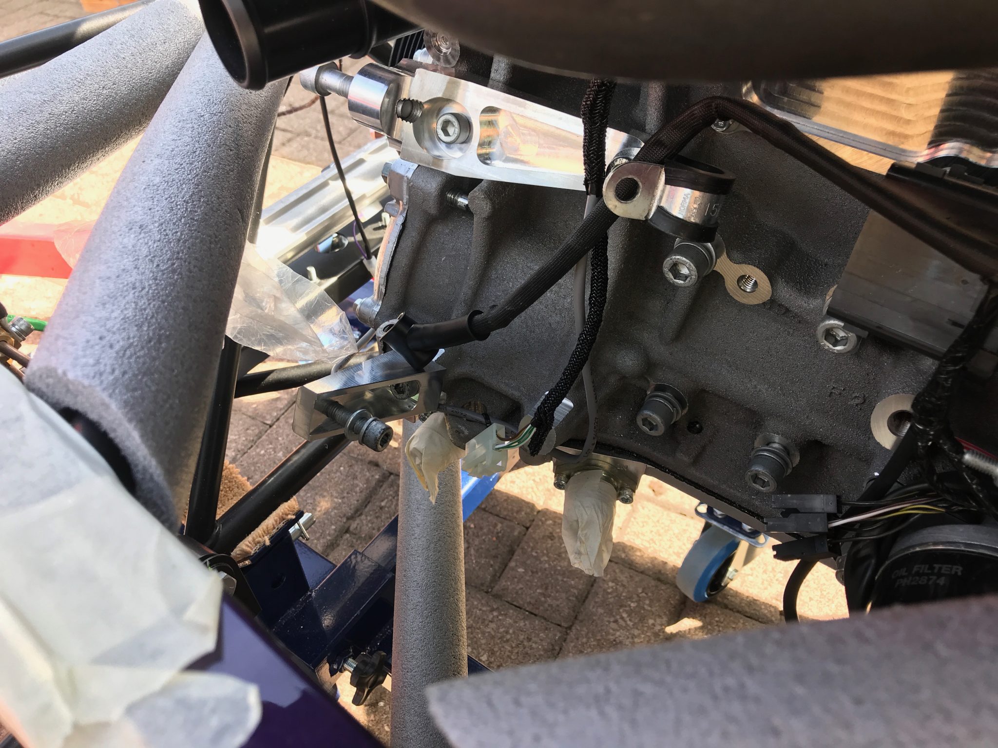
Engine Mount Struts Back On
When the engine was a few centimeters above its final home, it made sense to put the engine mount struts back on. They can’t go in until you’re really close to the final location as there’s a vertical chassis member set close to the ending mounts (which of course needs to be there for structural integrity around the engine mounts).
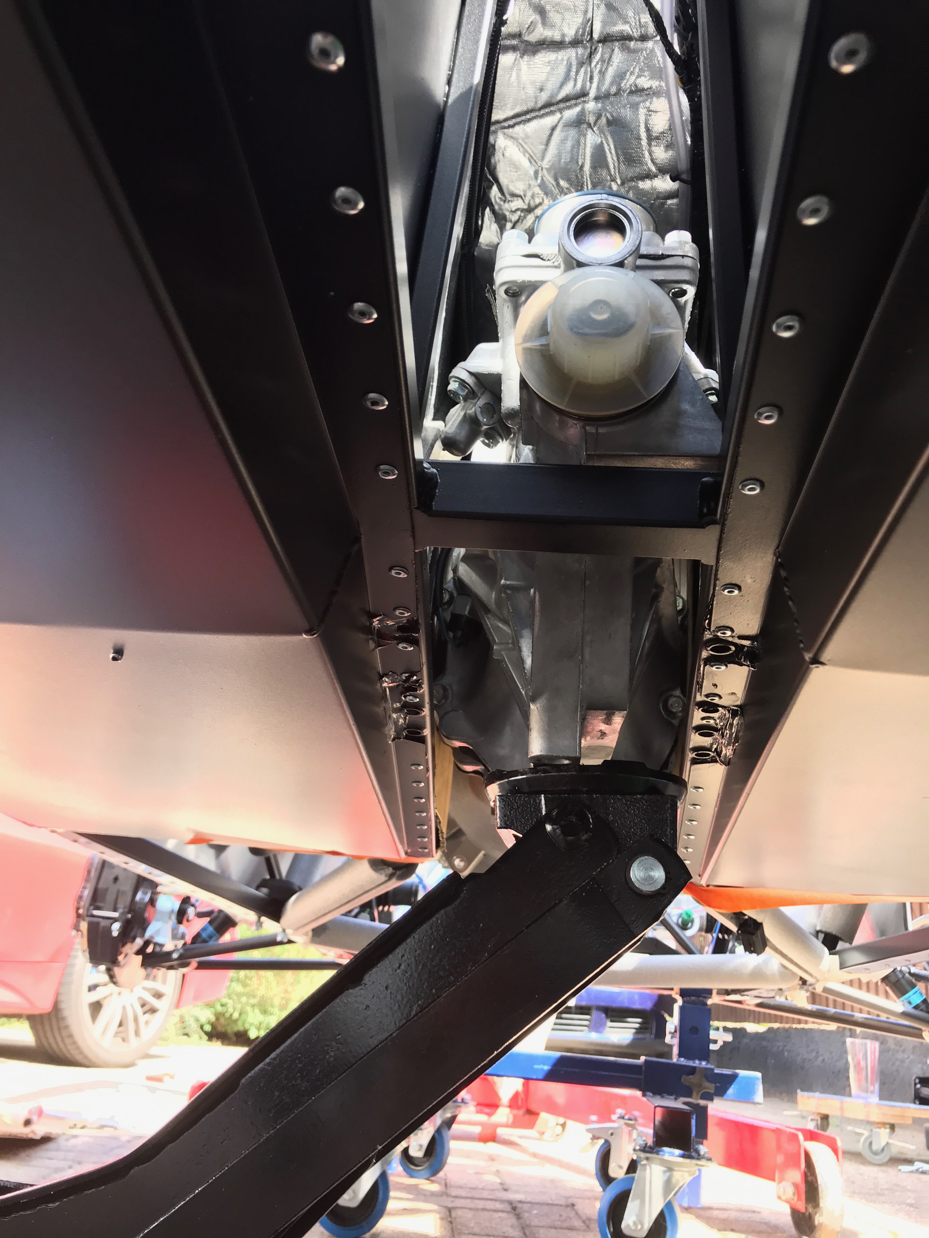
With the struts in place the engine can be lowered to its final resting place.
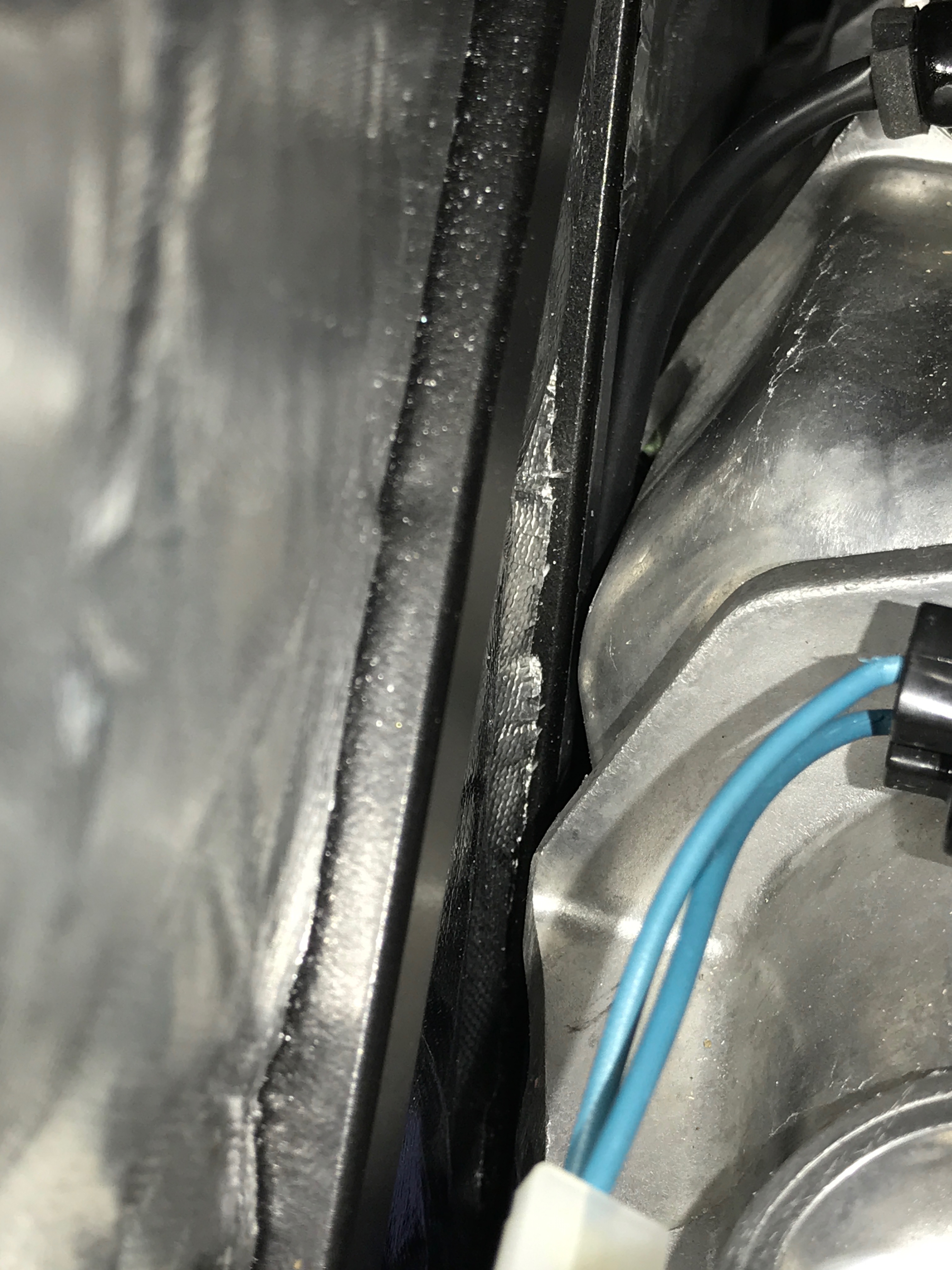
The final few millimeters caused us some more concern. The gearbox was really close to the LHS transmission tunnel walls. It was touching the heat shrouding and very close to a chassis member. I know every blog tells of how close the gearbox is to the chassis but I couldn’t believe it was this close. Surely its going to contact the chassis under cornering?!
I attached the gearbox mount to the gearbox with the two large M12 bolts and used the two front engine mount M10’s to guide the engine into position. I torqued up the bolts at this point… but later… undid them again.
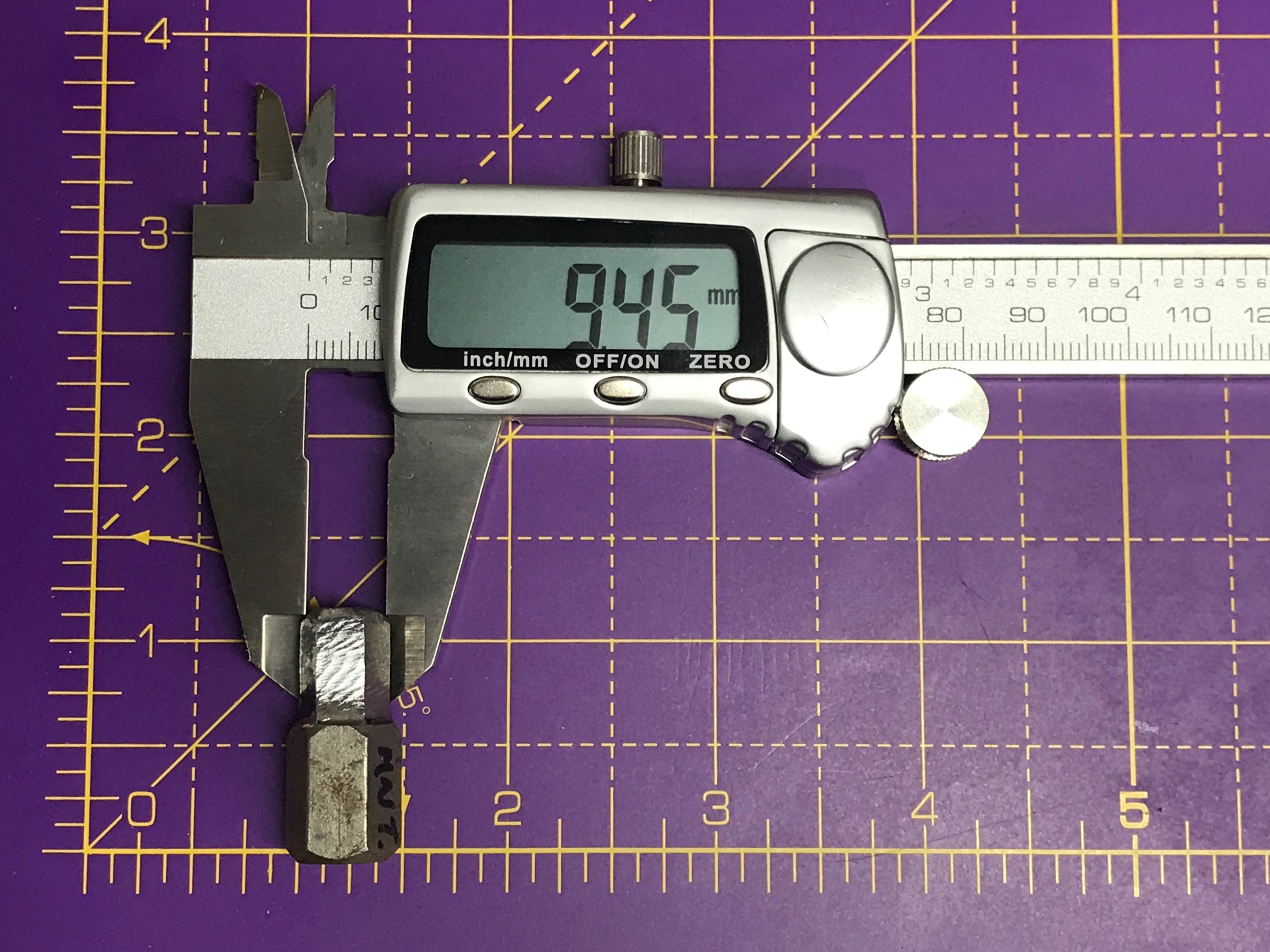
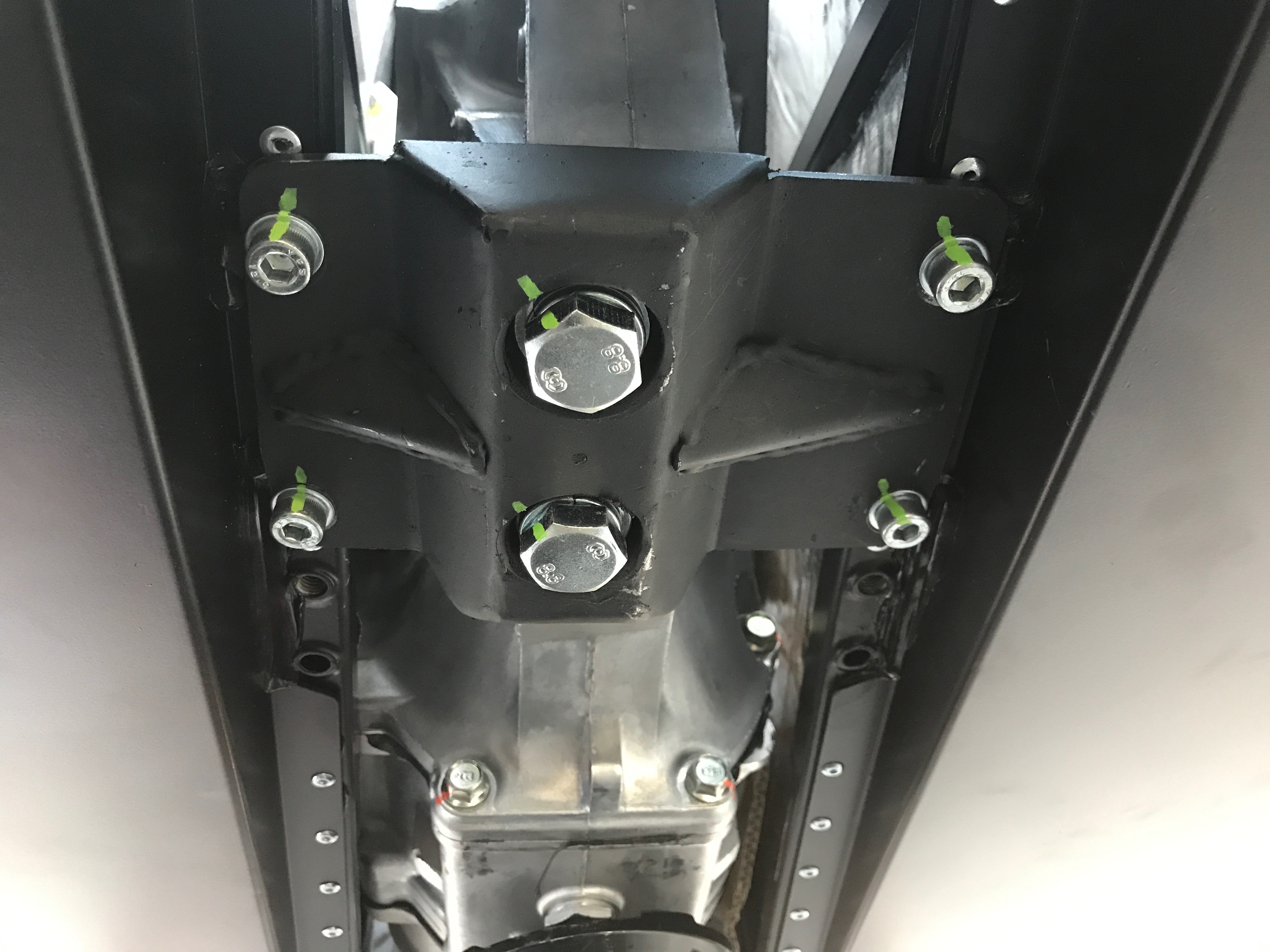
Imperial Cap Head Engine Mount Bolts
The rest of the team had left by this point. We finally had all the engine mountings in place but they needed to be tightened and torqued. The front bolts were only loosely in place, finger tight and only a few threads on. I’d appreciated that a special imperial hex Allen key was going to be needed for the front engine mount bolts but I hadn’t got around to buying one. I’d assumed that I’d have something that would be good enough in my box of Allen keys.
Nothing seemed to be quite right so I decided to grind a larger metric 12mm hex key, with a 1/2” socket connection, down to size. Out with the Dremel and 30 minutes later I had an imperial hex key.
[envira-gallery id=”803″]
The calipers say its around 9.5 mm from flat to flat (how hex fixings are measured). It’s a little loose in the cap head but fine for the job.
Gearbox Fixings
The manual talks about feeding the gearbox-mount-to-chassis bolts down from above and attaching the nyloc nuts from underneath – at least that’s how I read it. Instead, I decided to push bolts up from bottom and attach the nuts from the top. It didn’t seem to be any trickier to do it this way (you need to get a spanner on the top and torque wrench on the bottom) but the method to my madness was that with the nuts on top they would be kept out of the weather and therefore more likely to be removable if the time comes. The downside of this, of course, is that if a bolt comes undone it will drop out through the holes. Firstly, I don’t think this is very likely and secondly, these bolts aren’t very expensive… I’m more concerned about them seizing than coming loose.
The manual also talks about centering the gearbox in the transmission tunnel using the elongated holes (slots) in the chassis. As far as I could tell there was no play in the positioning of the gearbox in the transmission tunnel. I left the front engine mounts loose, left the gearbox suspended on the jack and left the engine hoist in place to take all the loading of the engine and gearbox mounts. We then tried to “shift” the engine/gearbox assembly in the tunnel but with no effect. It resolutely wanted to sit close to, but not touching, the LHS transmission tunnel chassis.
I even tightened all the engine and gearbox fixings at one point, lost confidence and undid them all again to try and move the gearbox over again. To no avail!
At this point, the engine was in. We could have left it there and called it a day but I wanted to get the alternator back on before the car was put to bed.
Alternator Belt Back On
Ted came back round again to see how we were doing, so between us we had a look at getting the alternator belt back on. It took a bit of discussion but we then realised how the top pulley is sprung. A 19mm socket and bar will push the pulley back so the belt can be slipped over it and the other pulleys. I knew this from taking the belt off in the morning but had somehow forgotten which bit to twist. If I’d gone back to my video it would have been obvious.
Ted left again having provided his managerial skill and I tightened up all the bolts, torqued them, painted the joints and tidied up. Once everything was tidy I rolled the car back into the garage and sat back in the glory of an engine united with its chassis!
Putting the Car Back in the Garage
All done up, time to put the car back in the garage…
Hoist back to Pete
Timings
I’m going to do a bit of man-maths here. On the project plan I said the engine install was going to take about 2 hours. In the end I was probably about right. It took about an hour to drop the engine in and an hour to prep the engine and then put the alternator back on and tighten up all the bolts.
What I hadn’t accounted for was a significant amount of time getting the leveller figured out… the playing around to see if we could get the gearbox away from the tunnel wall and then making of a hex key.
In the end we spent all day, which was 6 hours, on the engine install and associated tasks. It was quite a physical day too. Physical because of the continual jumping up and down between looking at the engine from above, checking it from underneath and jostling the jack, hoist and car backwards and forwards.
I’m glad we had a whole day to complete this task. I’d hoped to finish it off much sooner but in the end we didn’t have to rush and we could make sure we didn’t damage anything in the process.

Leave a Comment