
Back from a couple of days visiting family and had a few hours to get some prep done prior to putting the engine into the car tomorrow (Bank Holiday Monday).
Radiator Top “L”-Hose
The manual calls for the top radiator hose to be fitted to the engine prior to it going into the car. I guess there’s not enough room to get it in once in the engine bay.
However, in the “cooling” parts box, it didn’t seem to be obvious which of the hoses was the L-hose talked about in the manual. This hose, also called the top radiator hose later in the manual, is, in the end, much more complex than just an “L”. Once you get over the concept that you’re looking for an L-shaped object then there can only be one hose that works. And, once you offer it up to the engine you can see how it wraps around all the right bits and is contoured correctly for the install. You can then see that it has to pass under the air intake and would be tricky to install with the engine in the car.
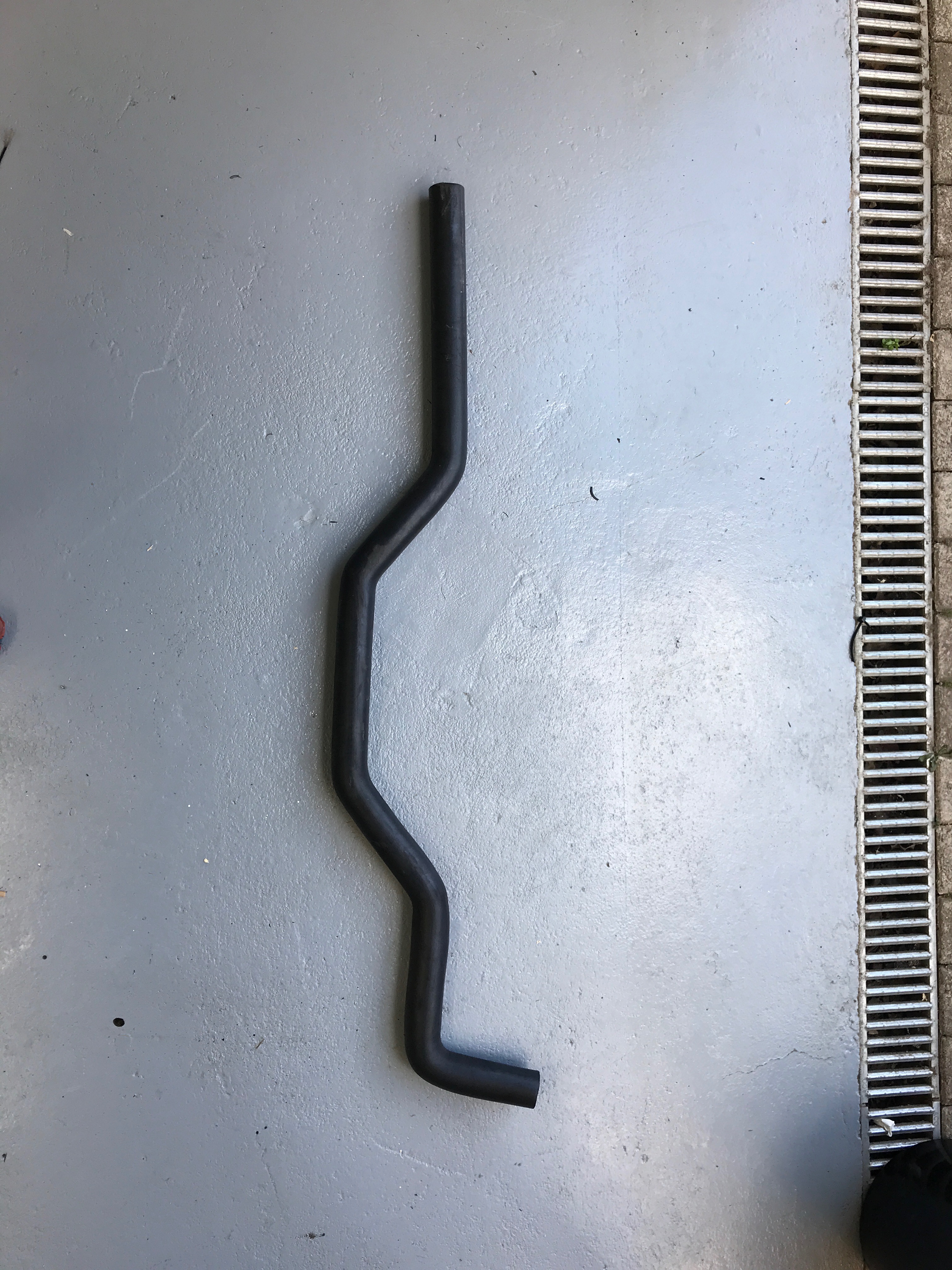
There is quite a bit of excess hose that pokes out from the front of the engine… looks like I’m going to need to remove 15cm or so once it’s finally in the car.
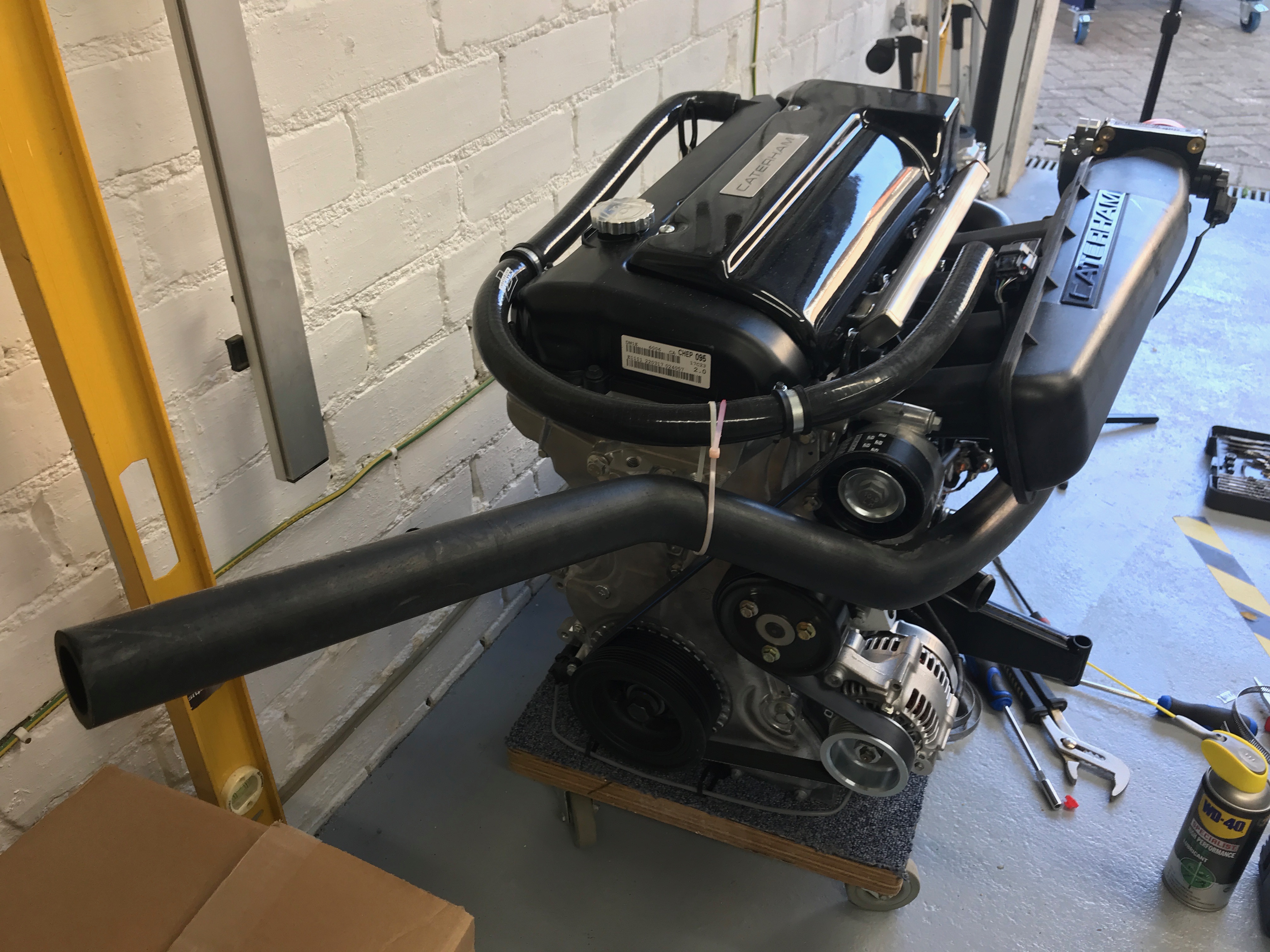
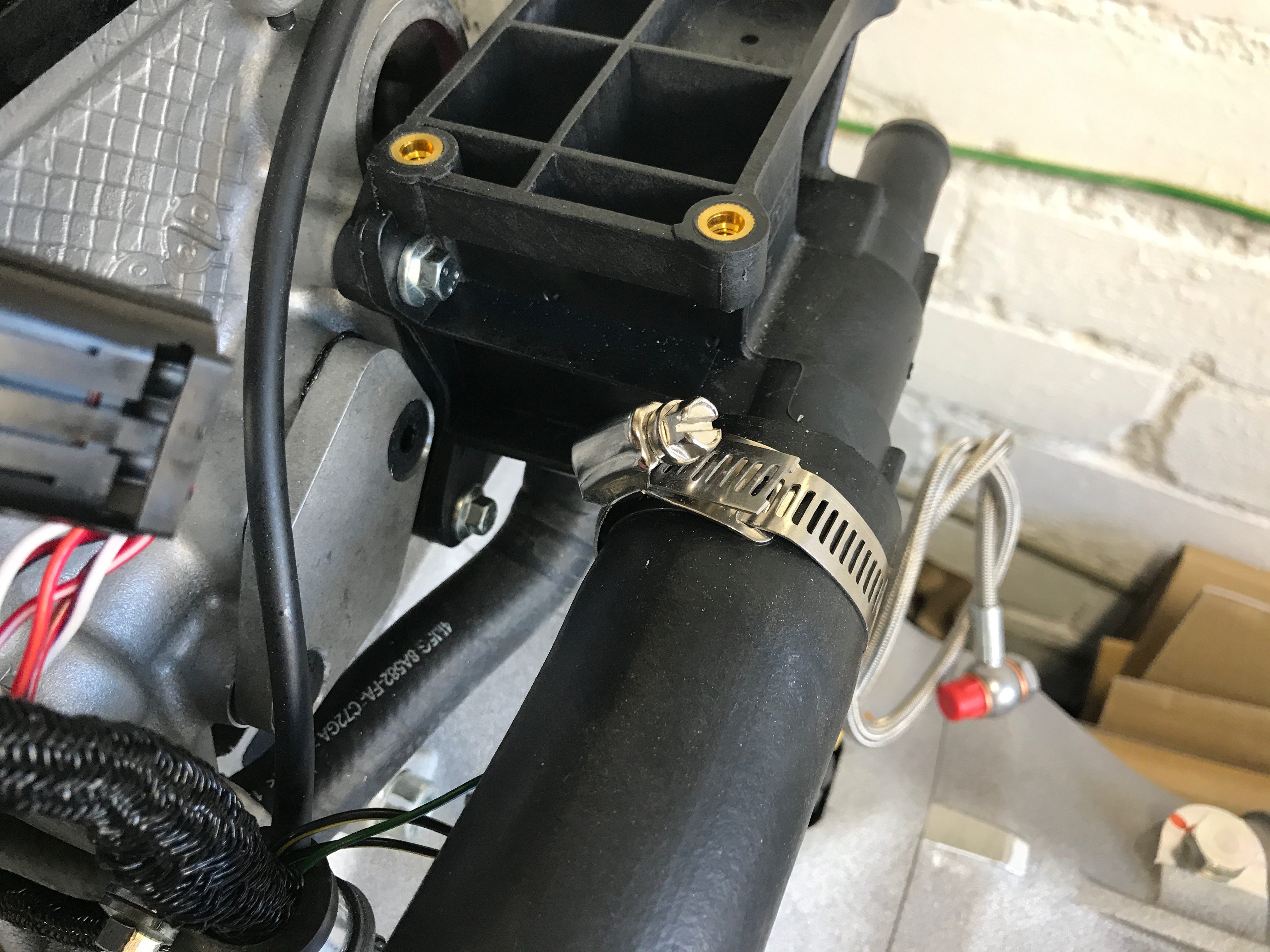
The manual now tells you to fit the hose and of course use a jubilee clip. However, I had fun and games getting the jubilee clip on. The biggest clips you’re given are 40mm diameter, but I ran out of patience with that and pulled out some bigger ones I’d bought as spares. I may try and get a 40mm clip on at a later date.
Engine Mounts and Earth Leads
The next “prep” job is to attach the engine mounts to the chassis. They are two metalastic discs with two ears to bolt through the chassis. I test fitted the bolts through the centre holes just to make sure there wasn’t any “rubber” residue in the threads – much easier to sort that out when you don’t have a 200kg engine dangling above them (when they’re in the car).
These may end up coming back out again as we put the engine in, but wanted to make sure I had everything sorted with them and the earth lead that attaches to the LHS mount. There are lots of stories about how little clearance there is when installing the engine, so I wasn’t sure if they would have to come out again to give room to manoeuvre at some point.
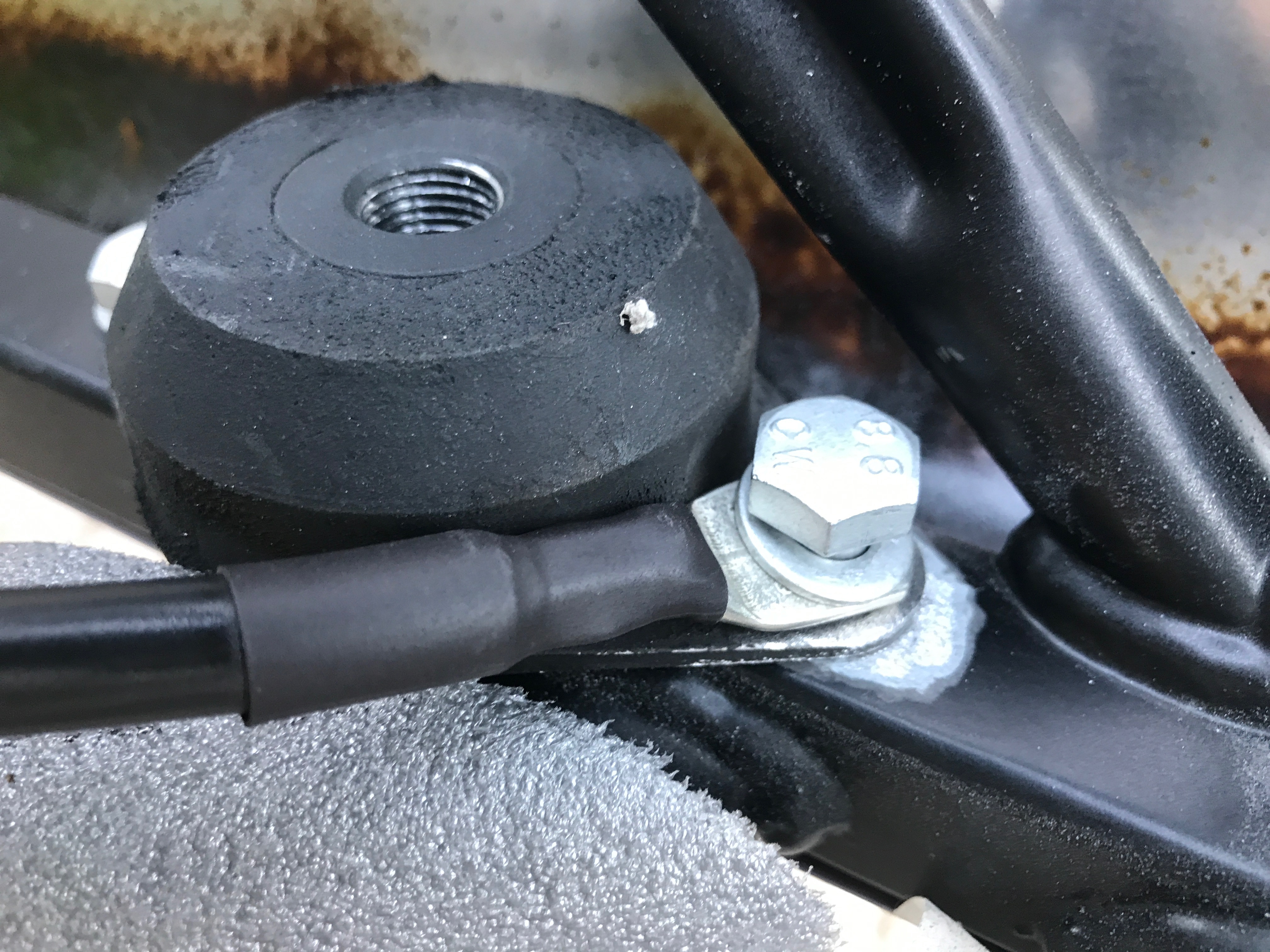
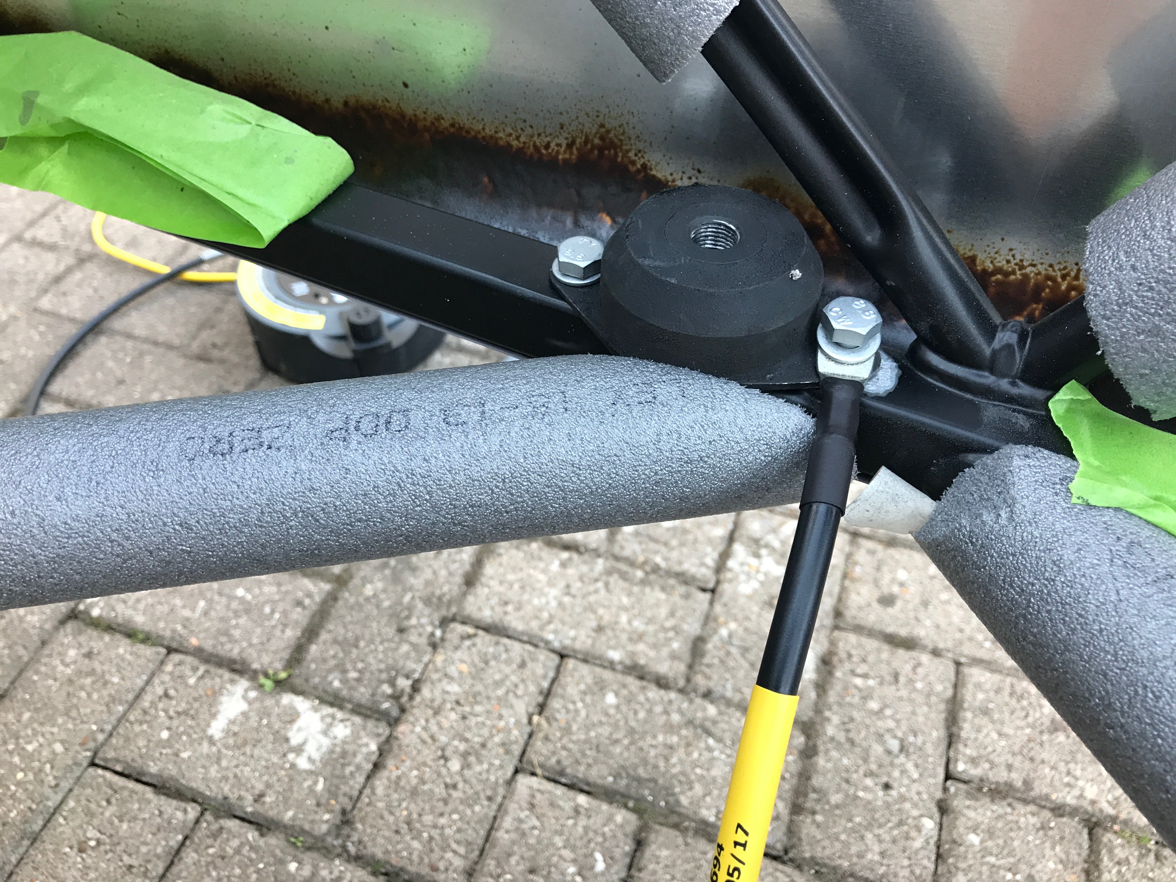
On the LHS (N/S) engine mount there needs to be a good earth between the engine earth lead, bolt, engine mount and chassis. To make this happen you have to remove some of the powder coating of the chassis so the metalastic engine mount makes a good electrical contact with the chassis.
Thinking this through some more as I write this, I don’t think there’s a lot of current passing through this connection. The biggest currents are going to be the cranking currents of the starter motor and I don’t think this engine mount will be the return path for that circuit. The starter motor grounds itself to the engine, and there’s an earth lead from the bell housing back to the battery that will therefore be the return path for the starter motor. If anything this mount is the return for the other electricals/electronics on the car. The same can be said for the alternator earth return, I don’t think it runs through the engine mount to chassis connection. Both will, of course, run through the bell housing to battery connection.
However, doing some research on battery earth leads I re-read in the Father and Son 420R blog that Caterham had added a second earth from the battery to a chassis point on top of the passenger foot compartment during the PBC (Post Build Check). I’d been wondering why there were three earth leads supplied in my kit but now it makes more sense. The leads are:
- LHS engine mount to LHS engine mount strut
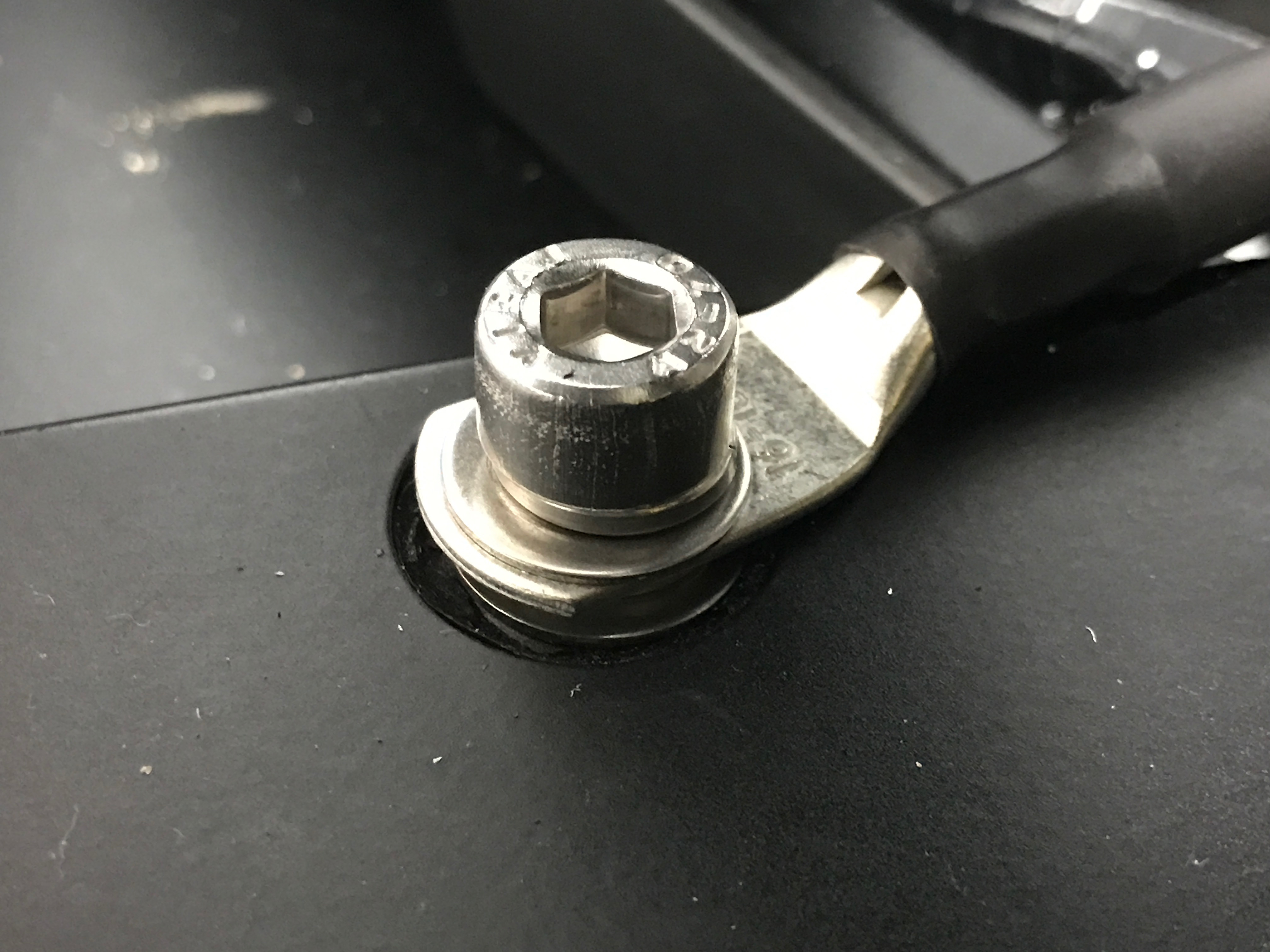
- Battery to RHS of bell housing bolt (need to remove bolt, attach lead and re-torque bolt)
- Battery to threaded insert on top of passenger footwell.
Looking some more at the passenger footwell connection: it looks as though Caterham have left one of the threaded chassis inserts un-plugged. These inserts mirror the inserts used to fix the pedal box on the RHS, so I’m guessing these inserts on the passenger footwell are for the left hand drive pedal box.
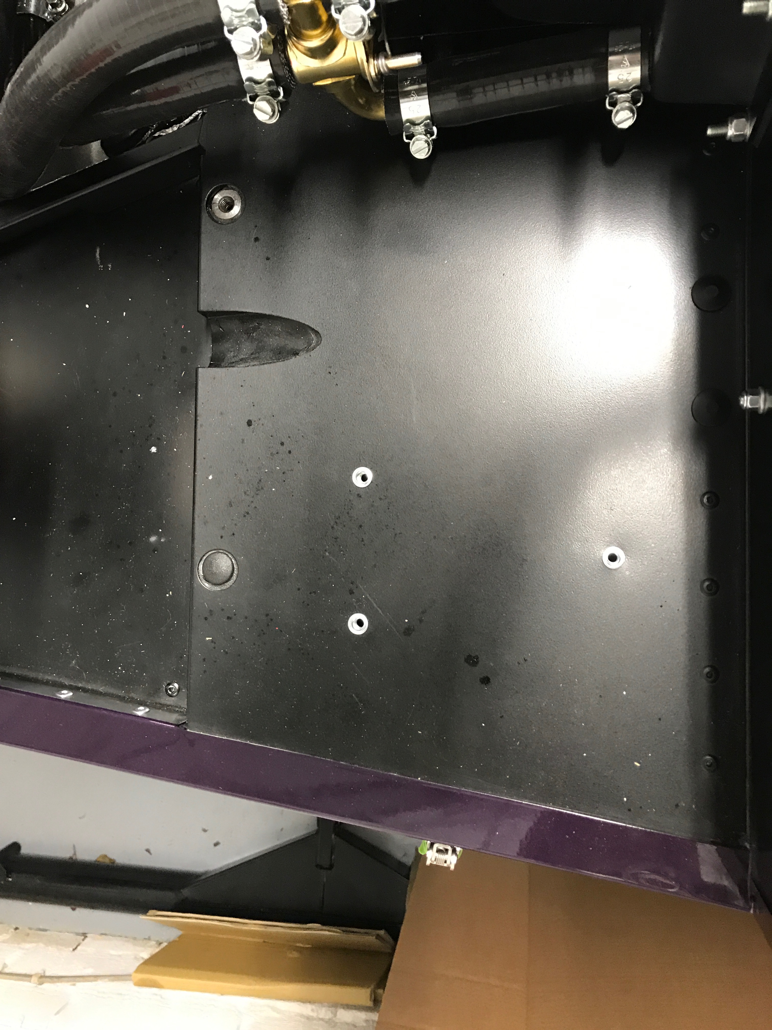
Perhaps the additional earth on the passenger footwell is there because it reduces the number of connections for the path from battery to chassis – it’s one hop from the battery to the chassis with this additional connection but two hops from battery to bell housing through the engine and then to the engine mount connection. It may also be that people don’t do a good job of getting the engine mount connected electrically and the insert in the passenger footbox is a much more reliable electrical earth point – it’s also out of the way of the water and grime at the bottom of the engine bay.
Having said all of that, with the two earth leads on now, the two main current sources/sinks, the alternator and starter motor respectively, will see a battery return path via both battery earth connections. They are essentially two very low impedance resistors… both very low impedance so they will practically share the current return to the battery. If Caterham were so concerned about the current load though then I think they’d have done more with the positive lead from the battery to the starter motor and alternator. That has a much longer run on it, with the battery cutoff switch installed, and the gauge of wire used is not much more than I’ve seen in cheap jump leads that can get rather hot if pushed on big engines. I’ve certainly had cheap jump leads get hot on 3L and 5L BMW’s in the past… we’ll have to see if that causes a problem with this “little” 2L engine with long crank times. Hopefully that doesn’t happen very often, but I’m not counting my chickens just yet.
Back to the engine mount though… Once I had the engine mount in and enough powder coat removed I tested the connection with a Multi-meter to check the ground.
Once the engine goes in I’ll coat the engine mount and chassis with black hammerite to protect the exposed metal.
Engine Hoist
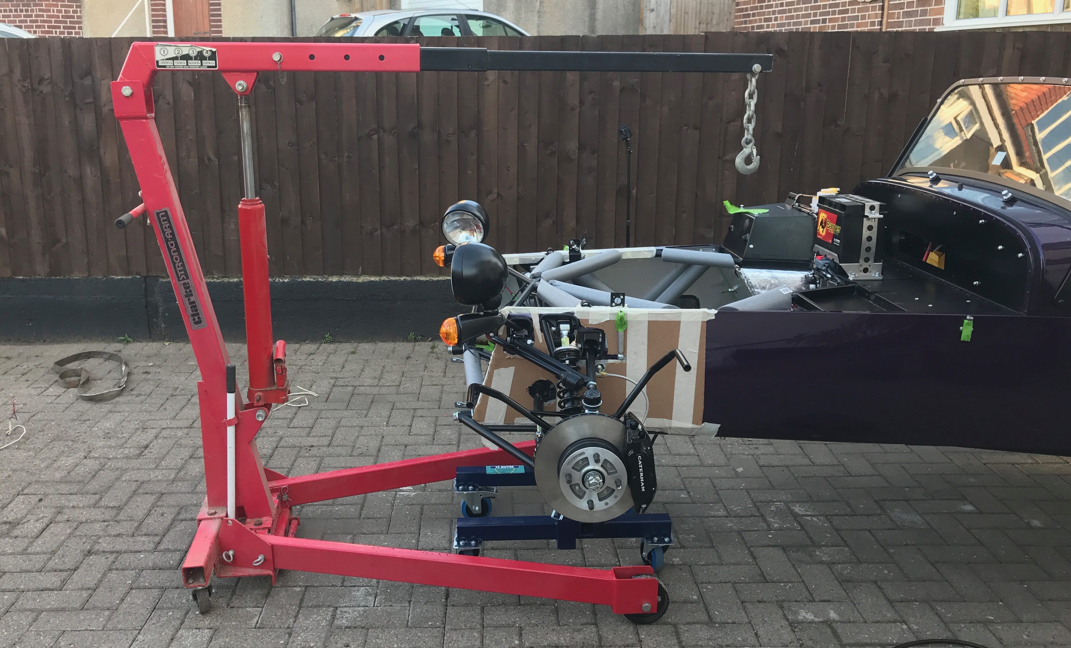
At this point Harry and I popped round to Pete’s (our neighbour’s house) who had kindly left us access to his engine hoist. A quick trundle and the hoist was on our drive.
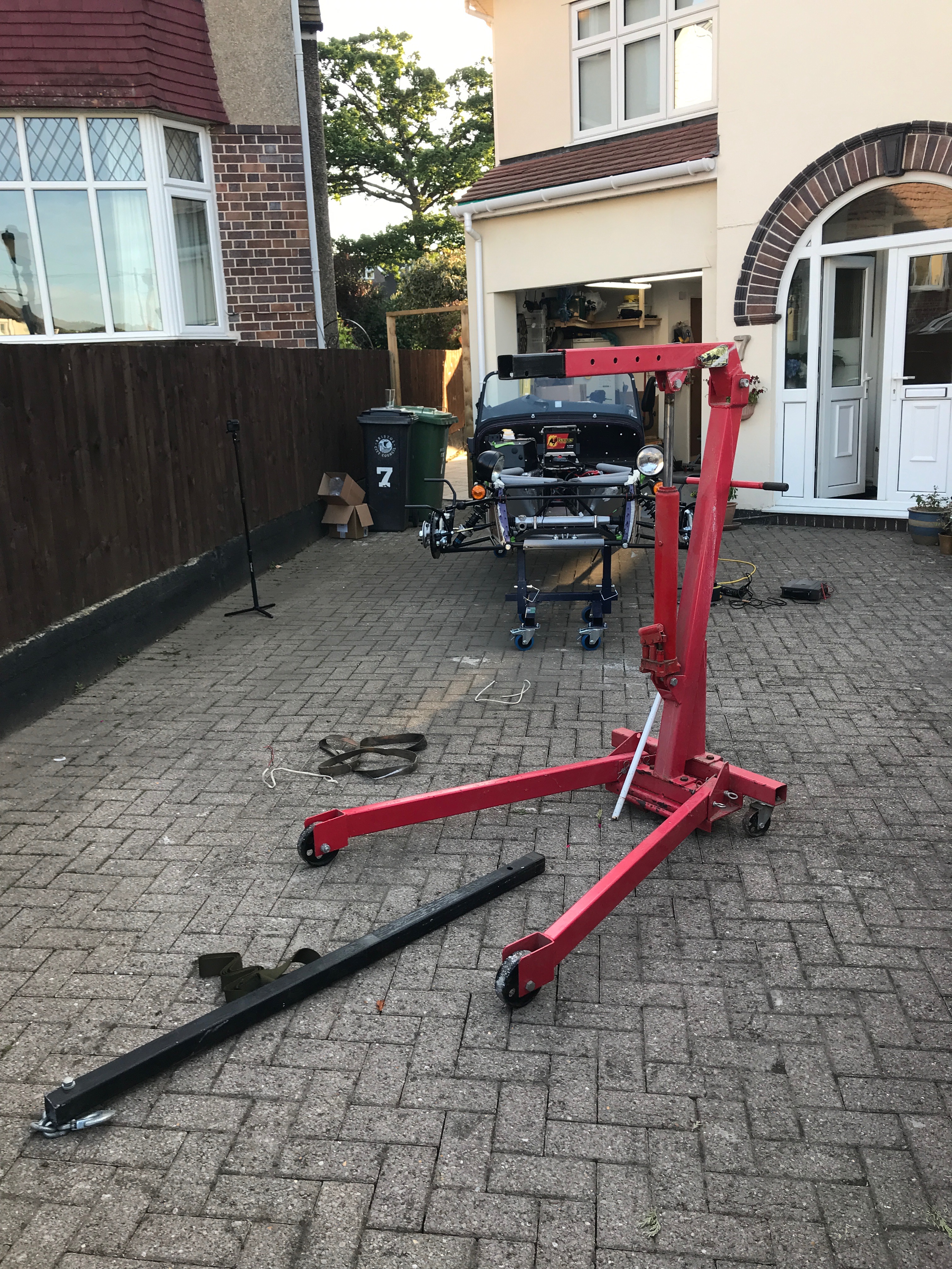
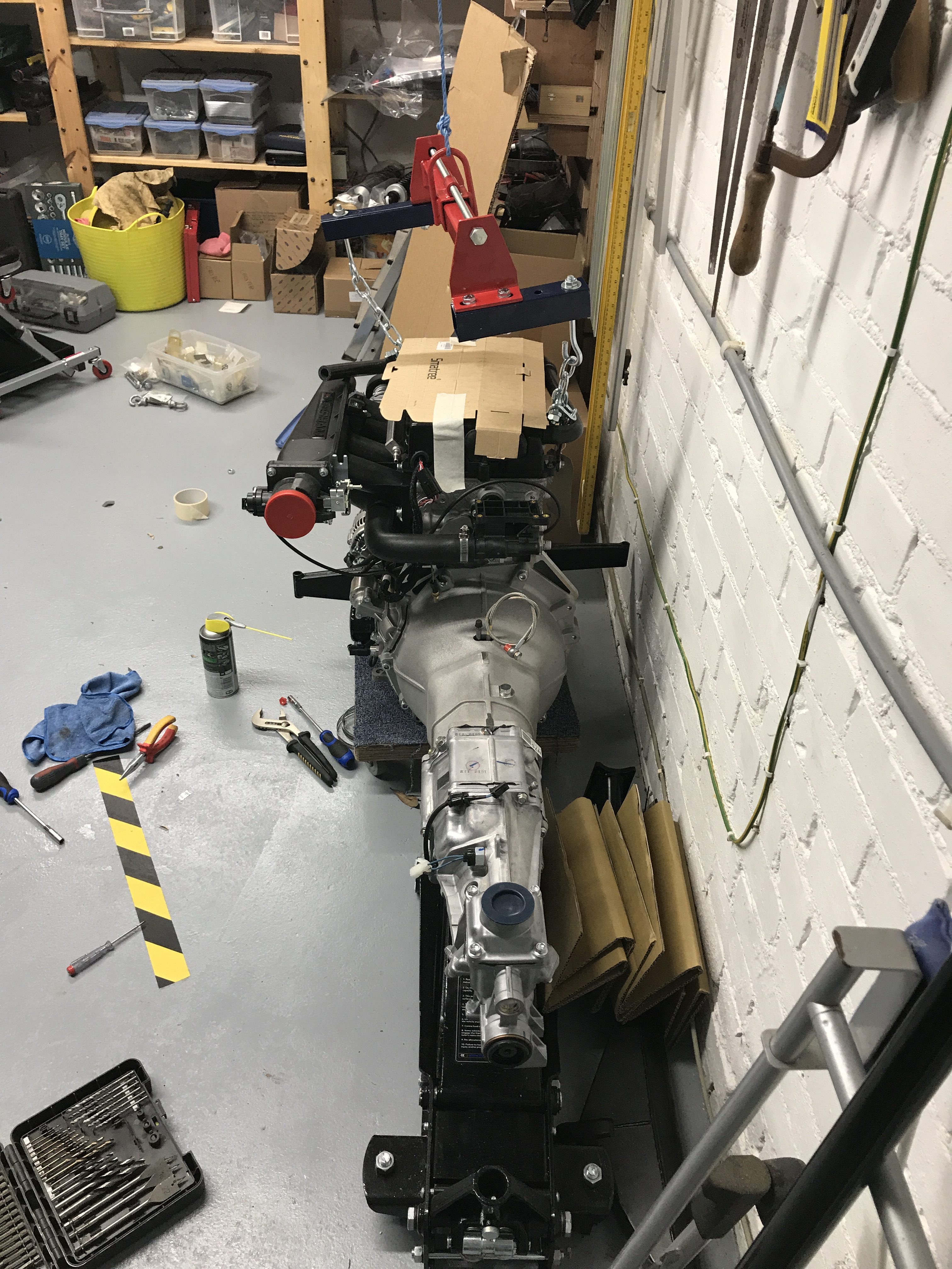
Pete has modified his hoist for increased reach using a long extension bar (the black bar on the ground in the picture above). Harry and I played around with a couple of configurations but it looks as though we’re going to have to use the hoist in it’s extended long arm config, but with as short a throw as the longer arm will allow (there are multiple alignment holes for each configuration).
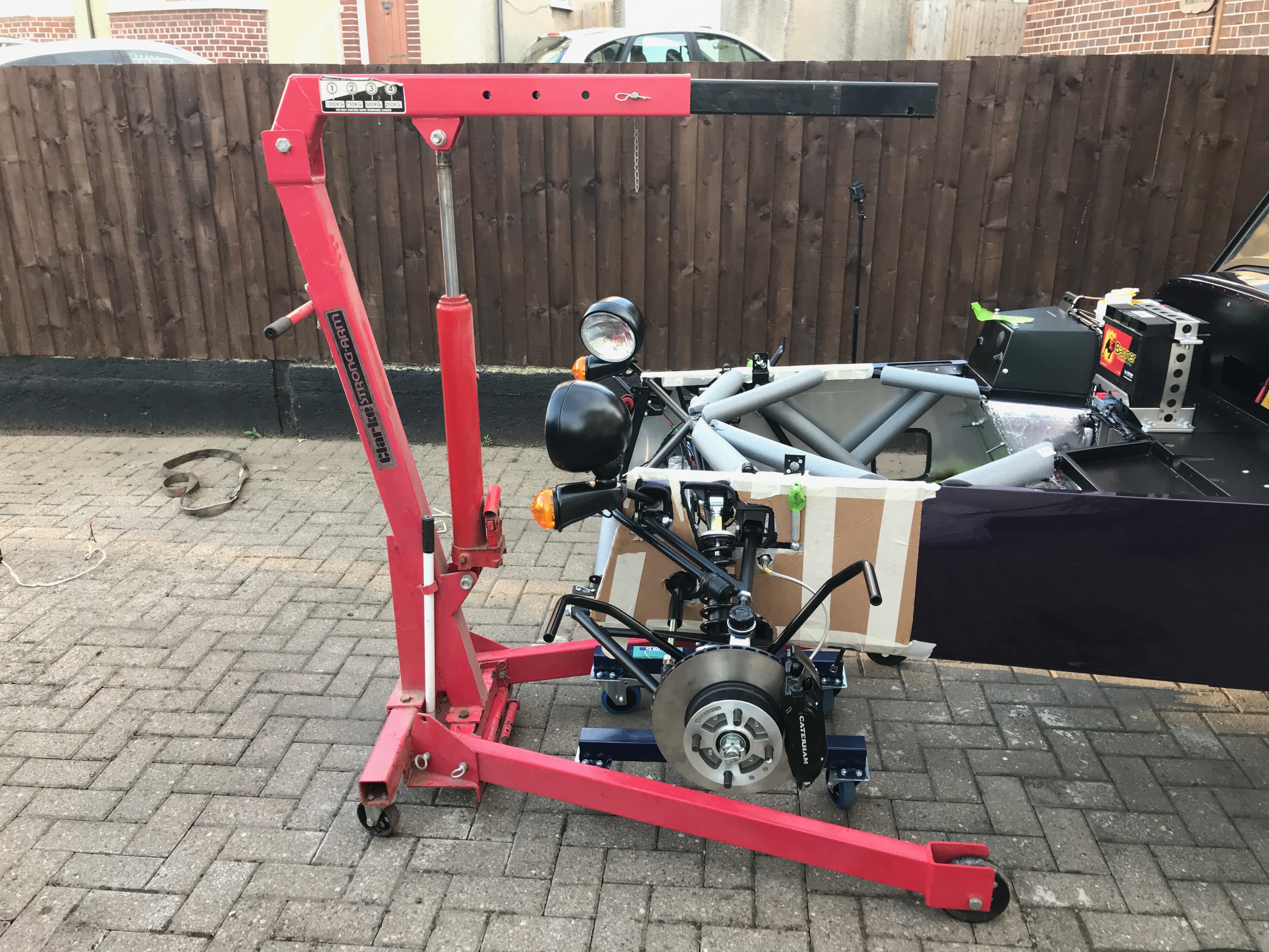

I’m concerned that the hoist will tip with the duratec engine and gearbox on it. You can see from the picture above that the chain and hook extend past the end of the hoist wheels – a recipe for disaster! I’ve done some research and it looks as though the engine and gearbox should be somewhere between 120 and 150Kg… I’m sure we can find some way to counter-balance the engine and stop any tips – a few bags of sand should do the trick.
Engine Hoist Extensions
We then got out the load leveller that I’d purchased a few weeks ago.
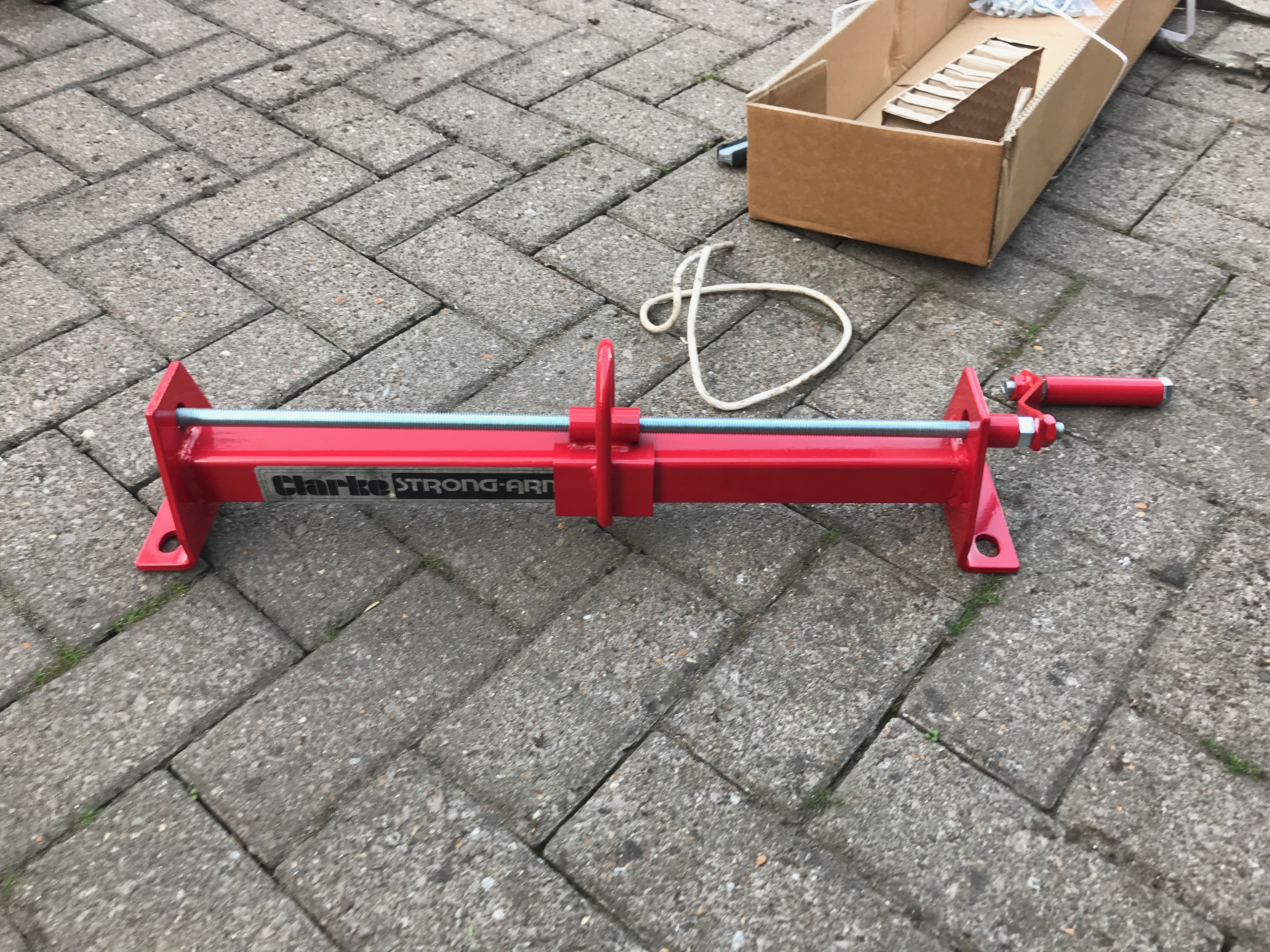
It’s a simple screw thread that shifts the engine around its centre of gravity. We’ve yet to try it in anger but it looks as though it will do the job.
One issue with any hoist arrangement with this engine is that the engine lifting points are at diagonally opposite corners of the engine.
Therefore, if you either strap it to a hoist or use something like a load leveller you will find that as you tilt the engine it tilts on the axis of the lifting points. i.e. it doesn’t tilt along the axis of the engine and gearbox assembly, it twists to one side.
To counteract this I thought that outriggers on the load leveller would allow me to attach the hoist straight up and down the axis of the engine, so counteracting the tendency to tilt non-axially.
I took some of the box section I’d cut off of the CJ Autos wheeled axle stands and fashioned some extensions. I drilled holes in the box section to attach to the leveller and then holes at the end of the box section to take the hooks of the leveller.
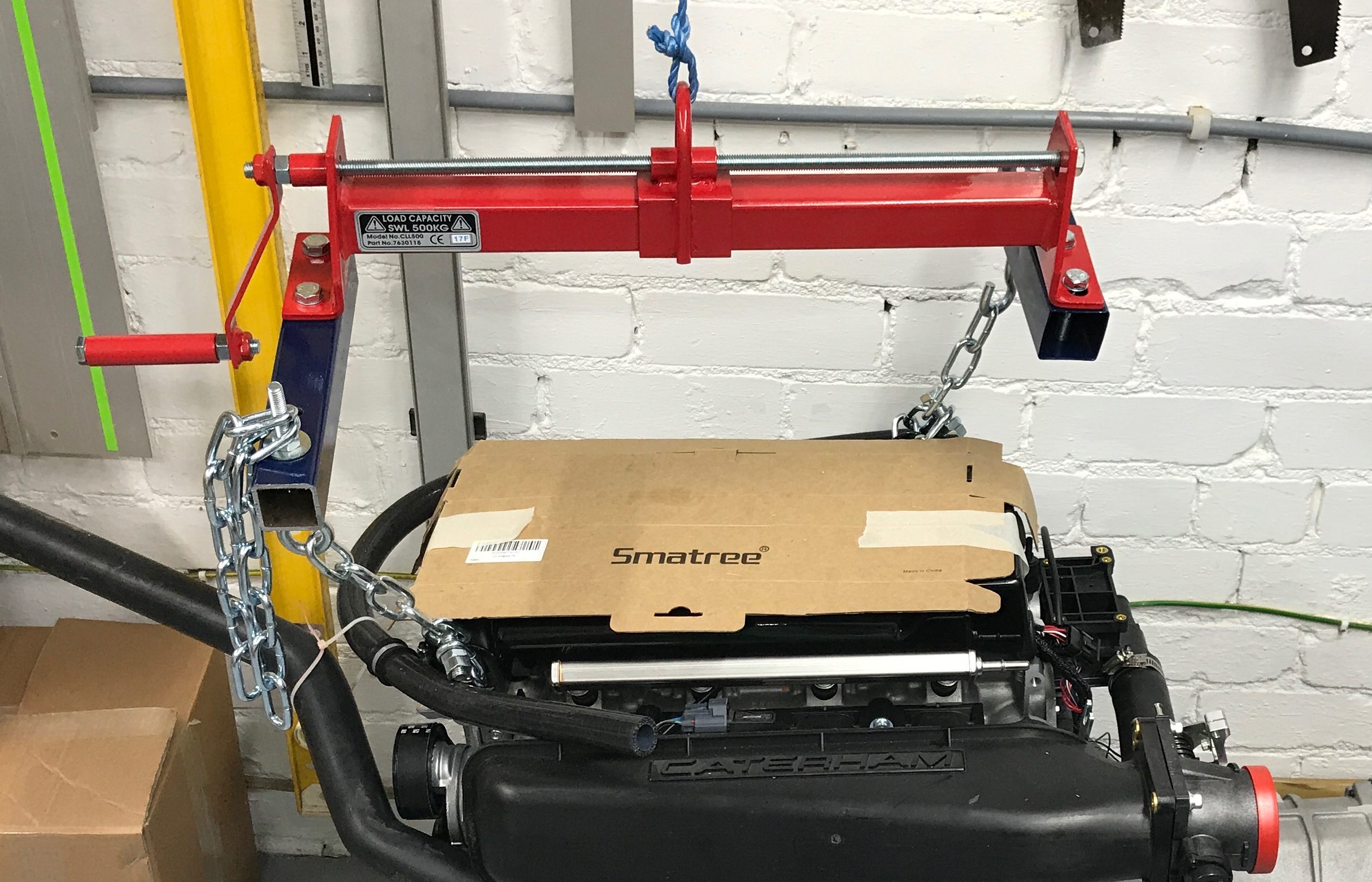
On setting up the leveller for the first time it was clear that the outriggers were not quite long enough and therefore not able to counteract the full non-axial tilt. I only had a certain length of box section and so had to make them as long as I could, but perhaps that’s not enough.
As you can see from the image below, the leveller sits more true to the line of the engine, but not quite perfectly so.
[ Note from later on… while I think the extensions made some difference. They didn’t completely straighten the twisting of the engine. I think it helped and was enough to mean we didn’t need to worry about the engine twisting as it went in, but it certainly didn’t stop the twist. I was half inclined to take the extensions off the leveller and see what difference it made with the full load of the engine and gearbox on it… but I decided we’d spent enough time fiddling with this solution and in the end – life’s too short! 🙂 ]
So, on with the engine install tomorrow. The weather is set to be good and so we’ll do the install outside on the driveway… another example of where the rolling axel stands are paying off.

Leave a Comment