
And so we’re off and running…. sort of!
Saturday morning broke and I was hoping to get a full day’s build in, but of course, things didn’t go to that plan. We ended up doing a bunch of chores around the house, and garden, and didn’t get off to a great start with the car.
And… once we did get going after lunch we got into some stuff not found in the build manual. It’s ironic that after all the preparation and reading of the build manual, the first job is actually not in the manual… but more of that in a second.
The first completely unscripted job was to get the axel stands sorted out. We’d left the car “on the skew” on the stands and the first job was to get everything central – we didn’t want the car falling off the stands with a nudge in the wrong place. We also needed to trim the axel stand cross members (hopefully saving our shins later on). A Caterham is signficantly narrower than a “regular car” at the points where you support it, so the cross members stuck out a long way on the stands. Out with the re-saw and off with the cross members.
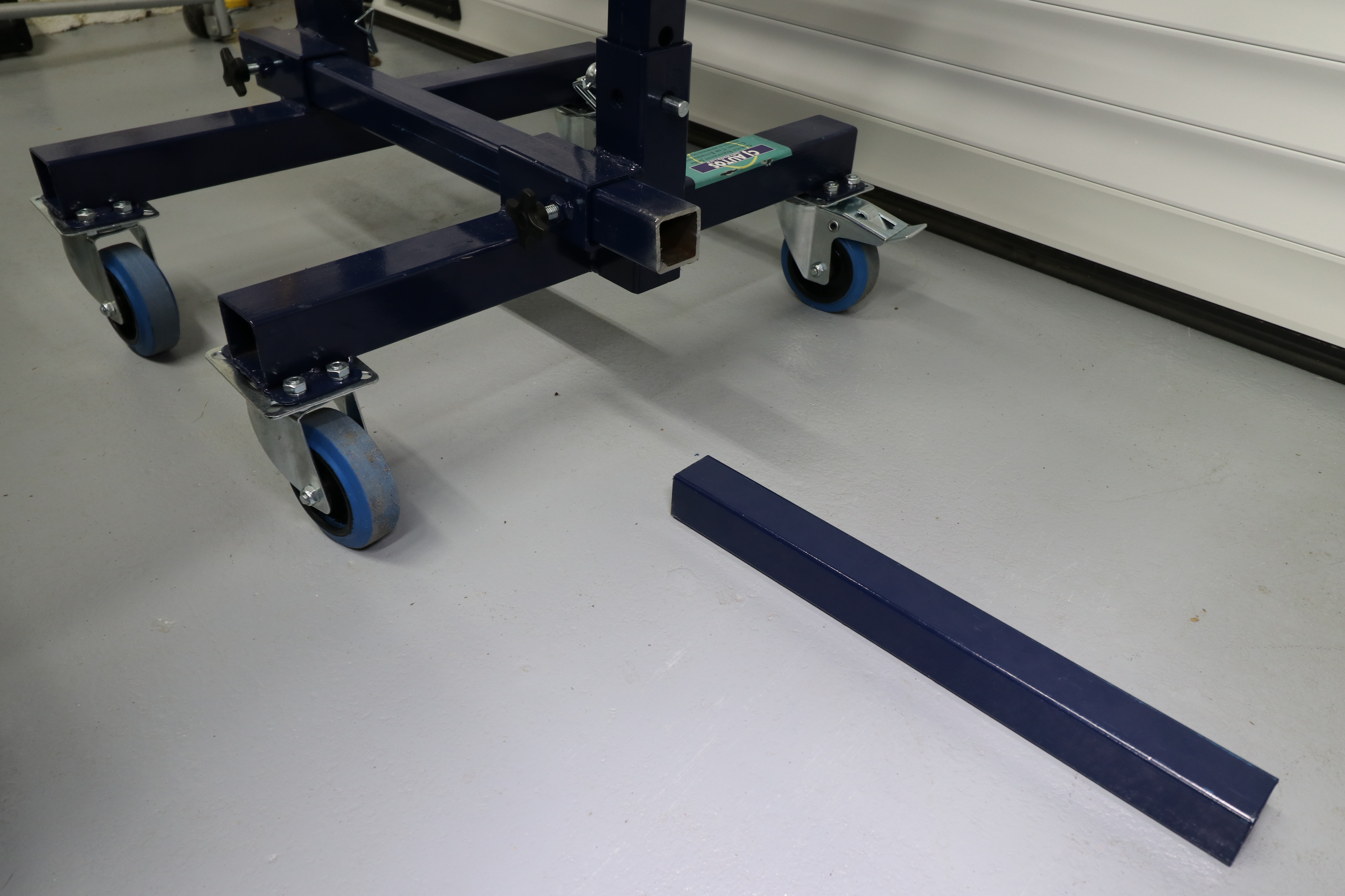
For anyone interested, we have the distances between the axel stands centres on this SV at:
- Front: 470 mm
- Rear: 930 mm
Bodywork Protection
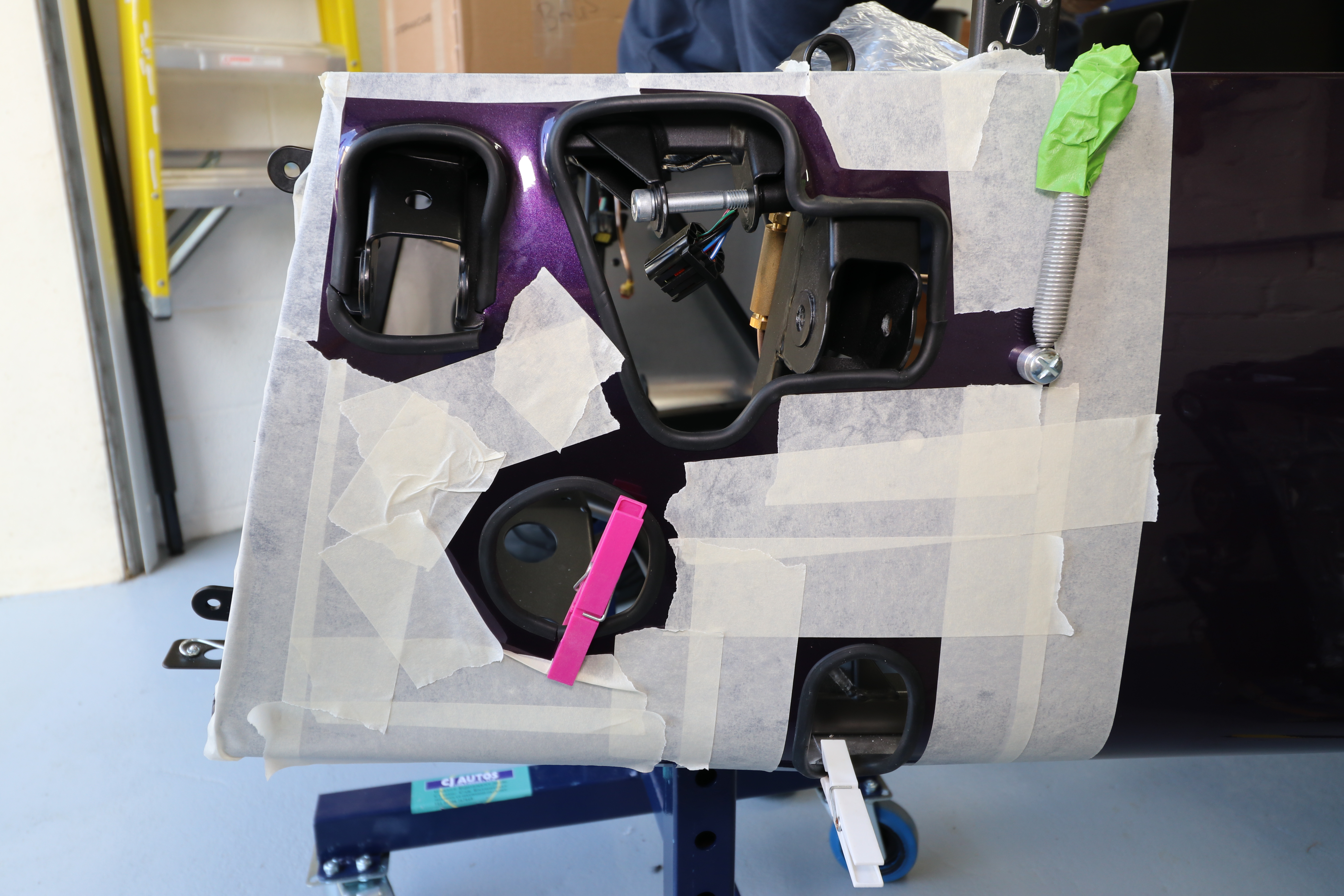
Next up was to get into the build proper… er, or not. We decided at this point that we’d apply some protection to the front of the car. The manual says to do this before installing the front suspension but we thought seeing as we were going to be fiddling with things around that area, it was best to protect the bodywork at this stage just in case.
We applied a layer of masking tape to the front two bodywork sections, but not really happy with it. That will need looking at again.
Front Suspension Apertures – IVA Trim
So, on with the Steering Rack… er, no!
All recent blogs recommend getting the IVA trim in place around the front apertures in the body work before starting on the front suspension. Ok, so hold off on the first step in the manual (steering rack) again and lets get into the IVA trim.
After pulling the IVA trim out of the IVA bag it struck us that we’d not seen anyone post about what orientation you have to put the trim onto the car with. The profile of the IVA trim is such that there’s a long edge and short edge, see below:
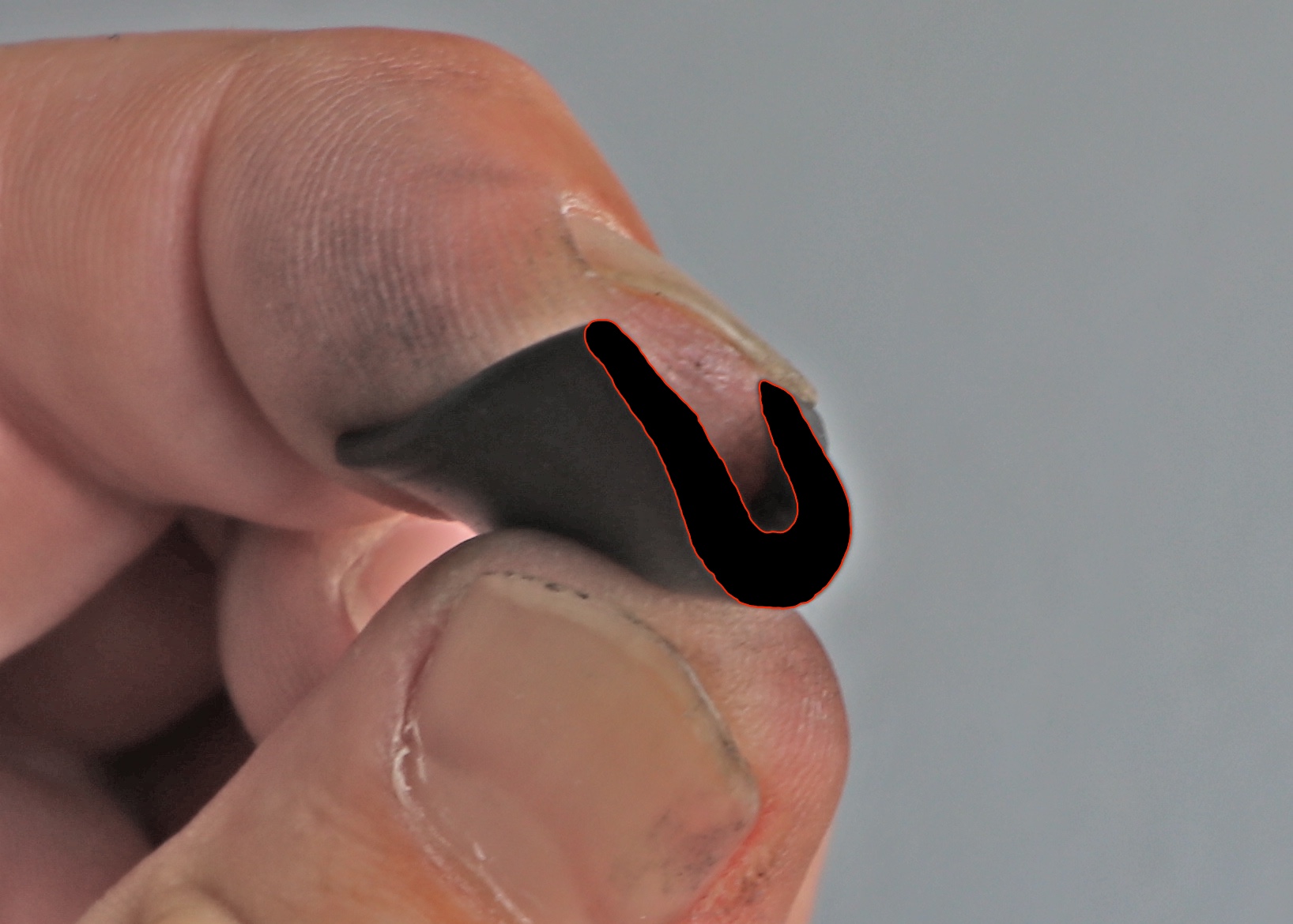
I searched a couple of blogs to look at pictures (by this time I now had an iPad sat permanently in the garage with as many blog sites open on it as I could find) but they were either inconclusive or what I thought to be wrong. It seemed to me that the shorter profile section should be on the outside and the longer on the inside of the bodywork panels; that way there would be more of the profile on the inner edge and the part you want to apply glue to. Back up a bit there… I’ve read in various places that super glue is what you want to use to stick the trim to the bodywork (a dab every one, two or three centimetres – depending on the radius of the section in question). But applying super glue to the painted front face is possibly going to be a one way street – taking it off may take some paint off with it (some have reported needing paint to be touched-up in exactly this scenario). So, the plan is to only apply super glue to the part of the trim that sits on the bare inside of the aluminium panel. Therefore… you want the longer trim piece on the inside to give you more to stick to the inside of the panel. Hope that all makes sense.
Having, therefore, looked at a bunch of blogs and not got conclusive confirmation of my theory, I turned to the pictures I’d taken of a factory built 420R at Williams a few weeks ago. Luckly I had one picture of the front suspension and it seemed to show the short profile on the outside. That was enough confirmation for me and so the trim went on with the short profile outside and the long profile inside.
Later on whilst talking to Derek Howlett, he also confirmed that this was the right approach (but more on that in a later post).
The trim went on fairly easily, though it was time consuming. We probably spent a couple of hours doing both sides of the car. As other bloggers have said, you need to cut, or slit, the trim to allow it to sit flat on the panels and for the glue to do its job.

In the end we found that we could, mostly, dry fit the trim and then apply glue to the inside profile by lifting up the trim and squeezing some glue in. That didn’t work in all areas, where the trim got close to the suspension mounting points, but it allowed us to make sure there was no glue on the Aubergines.
We used clothes pegs to apply pressure while the glue set.

It’s also worth noting that we decided to put trim around all edges of the apertures. I think I read somewhere that this isn’t a requirement for IVA but we thought it looked better anyway… and we’re not sure if the trim will remain in place after the IVA check, but we wanted to make sure it looked the way we wanted it to look, just in case, for the long term.
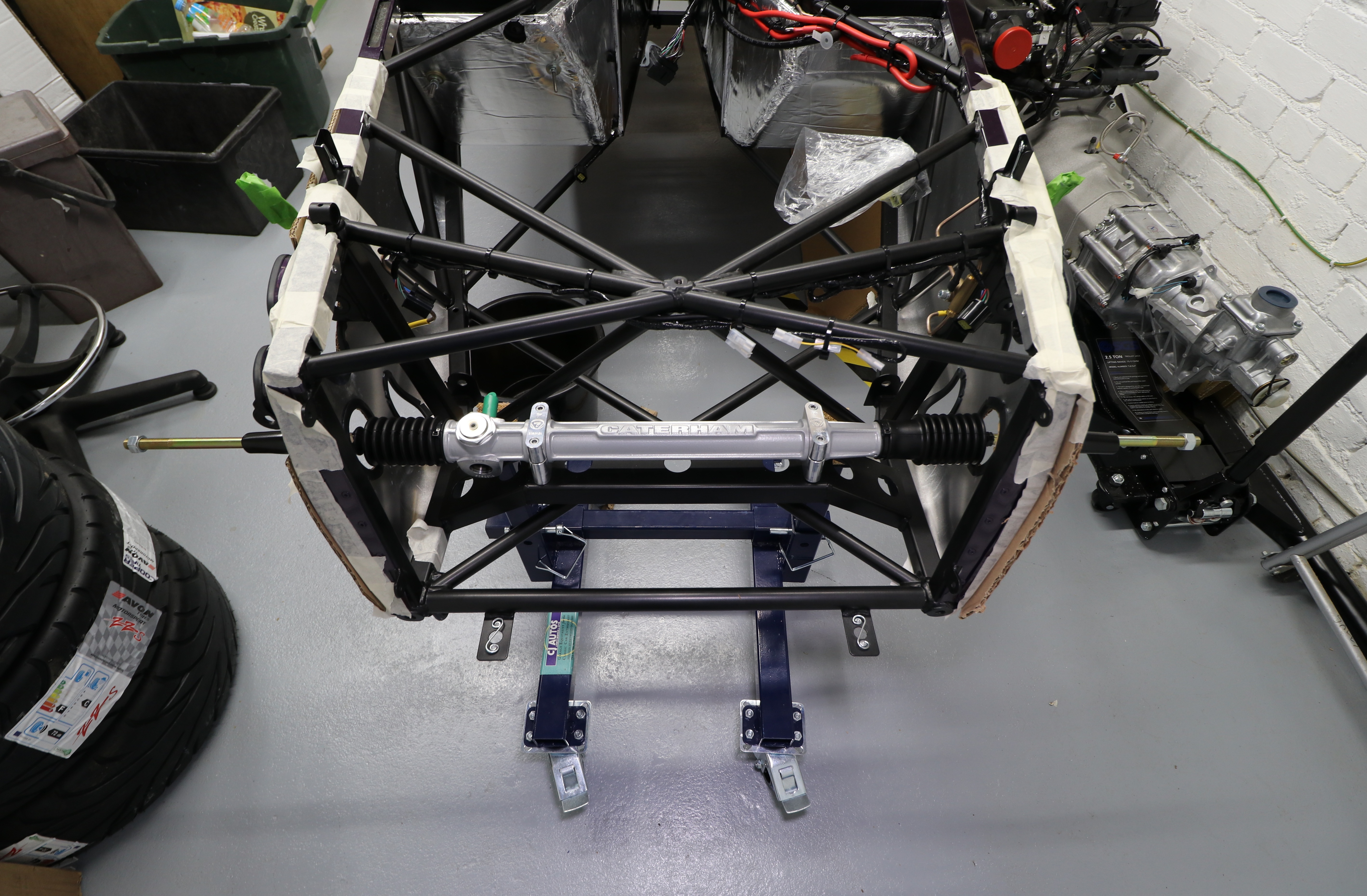
Steering Rack
Finally we’re adding something non-cosmetic to the car!…
…In the end I’m not sure we did the right thing with the steering rack.
This should have been a short job, but turned into something like an hour and us having to put the rack in and out 3 or 4 times.
The first problem was the fit of the rack into the machined aluminium mounts. One side was a snug fit into the mounts, but fine. The other just didn’t fit. There was overspray on the rack in the machined slot where the Al mounts sit. We could have just tightened the mounts up on top of the overspray but I was worried that doing so would have meant it would have been difficult to take the rack off again at a later date. It would also have meant that we would have had to have left the mount really, really lose in order to be able to line up the rack to the steering column later. No matter how careful we were going to be in lining up the rack now to where we thought the steering column was going to land on its spigot, we just weren’t going to get it perfectly lined up.
So, out with the Dremel, and files, and remove the overspray. However, this still meant the mount was really tight, but much better.
Next we fitted the rack but found that the cap head bolts had bound in the top machined aluminium mounts. Looking back at this now I realise that this is probably how they should be. But at the time it seemed to be a problem as it was tough to get a spanner onto the bottom nyloc nut and to do-up the nut/bolt from the bottom. We therefore thought we had to tighten the mount up from the top but the bolt was binding in its hole. So… we opened up the recesses for the capped bolt (after using a copper/leather hammer to extract the bolts from the mount). The cap head bolts are just under 10mm in diameter so putting a 10mm drill down the recess and wiggling a little was enough to open the holes out just enough to allow the cap-head to be free in the recess. On reflection, I should have used a socket on the nyloc nuts and allowed the cap-head to bind. No harm done I don’t think.
I suspect the cap-heads are meant to be tight in their recesses so there’s no chance of any play in the mounting of the steering rack. Having the rack wobble around under heavy cornering loads (need to think about whether there’s any load on the rack under cornering, but there must be some) would not be a good idea. [ Edit note: I’m not sure the makes any sense, if the rack and mounts are not tightened enough then there will be play around the bolt passing through the rack cross member near the nyloc nut – I doubt the interference fit of the cap head in its recess is that important. Please leave me a comment if you have an opinion ].
It’s also perhaps worth noting something that I’ve not seen others comment on: to get the steering rack into the car, you can’t feed it through from the outside of the car. The steering column spigot gets in the way and won’t fit through the holes in the body work. You have to feed the rack from the inside through the N/S hole then bring it back so the O/S track rod goes through its hole.

Tomorrow we’ll get onto putting in the front suspension.

Leave a Comment