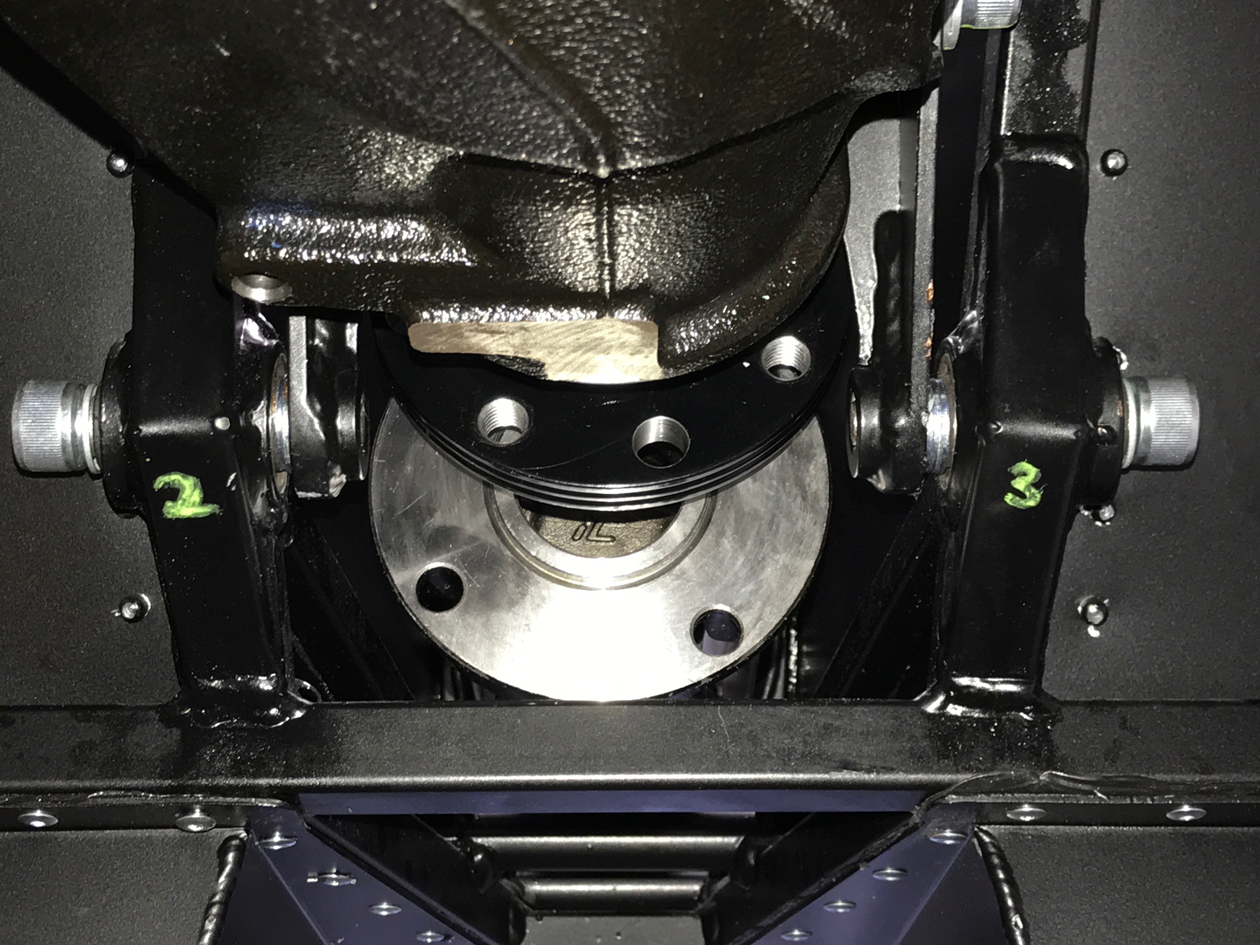
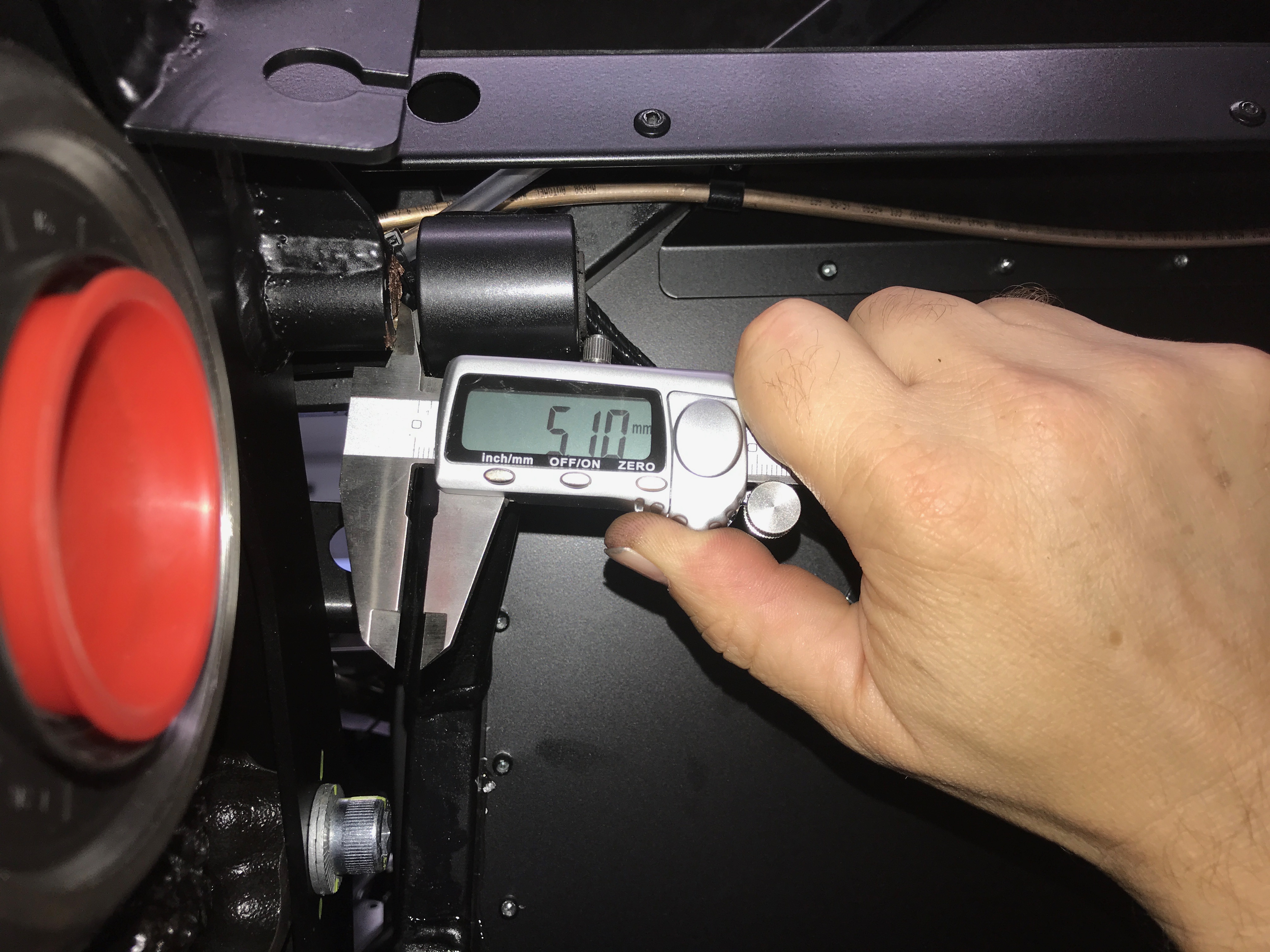
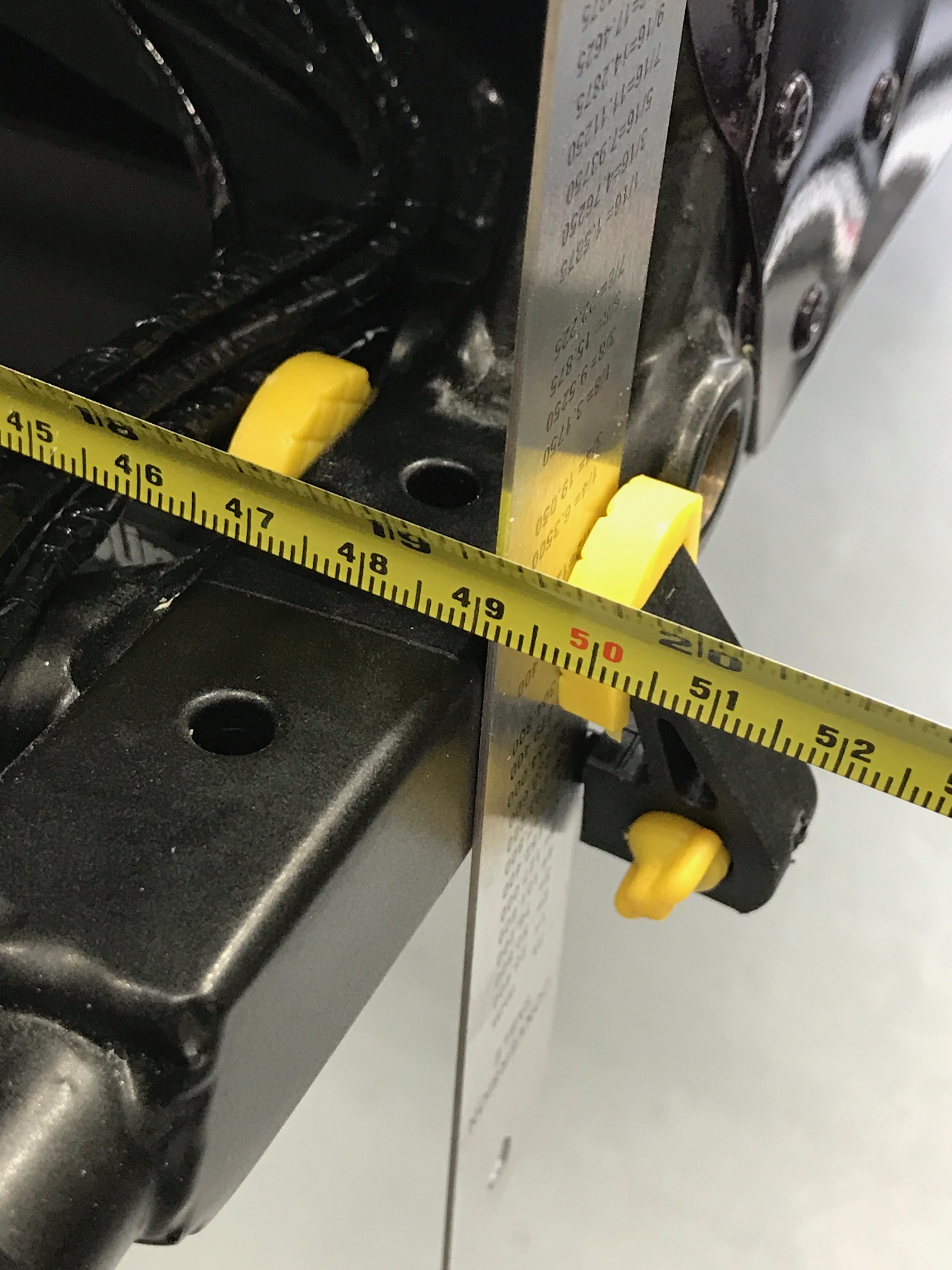
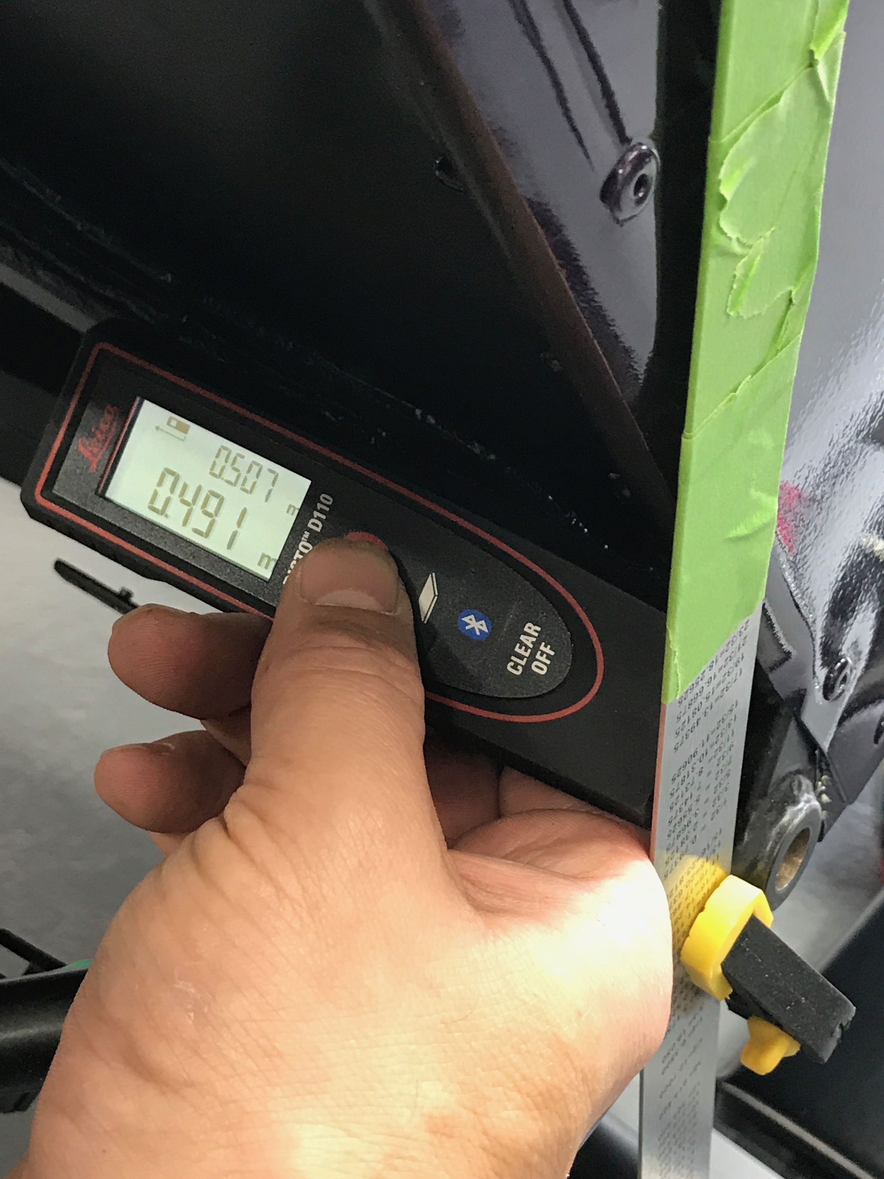
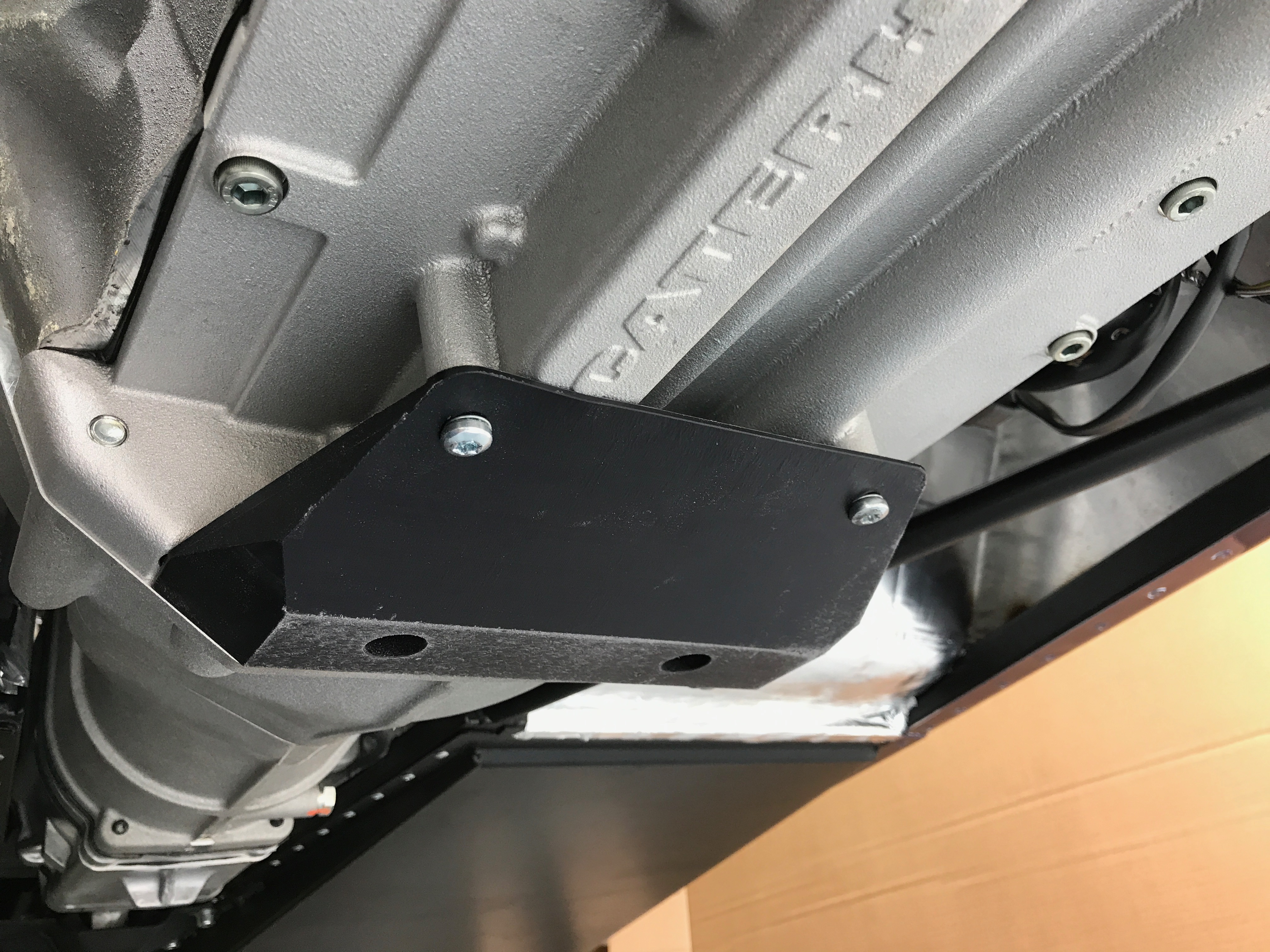
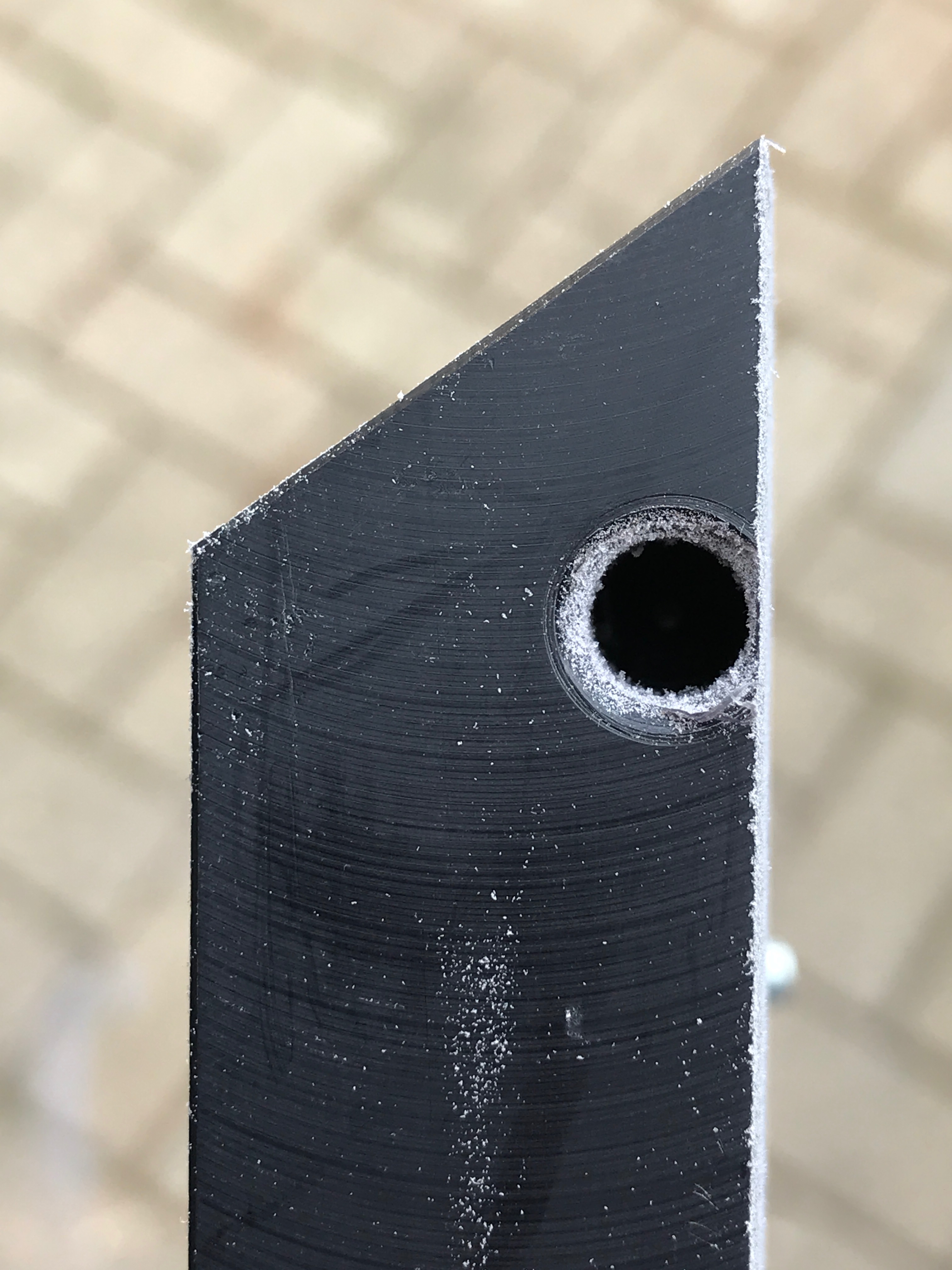
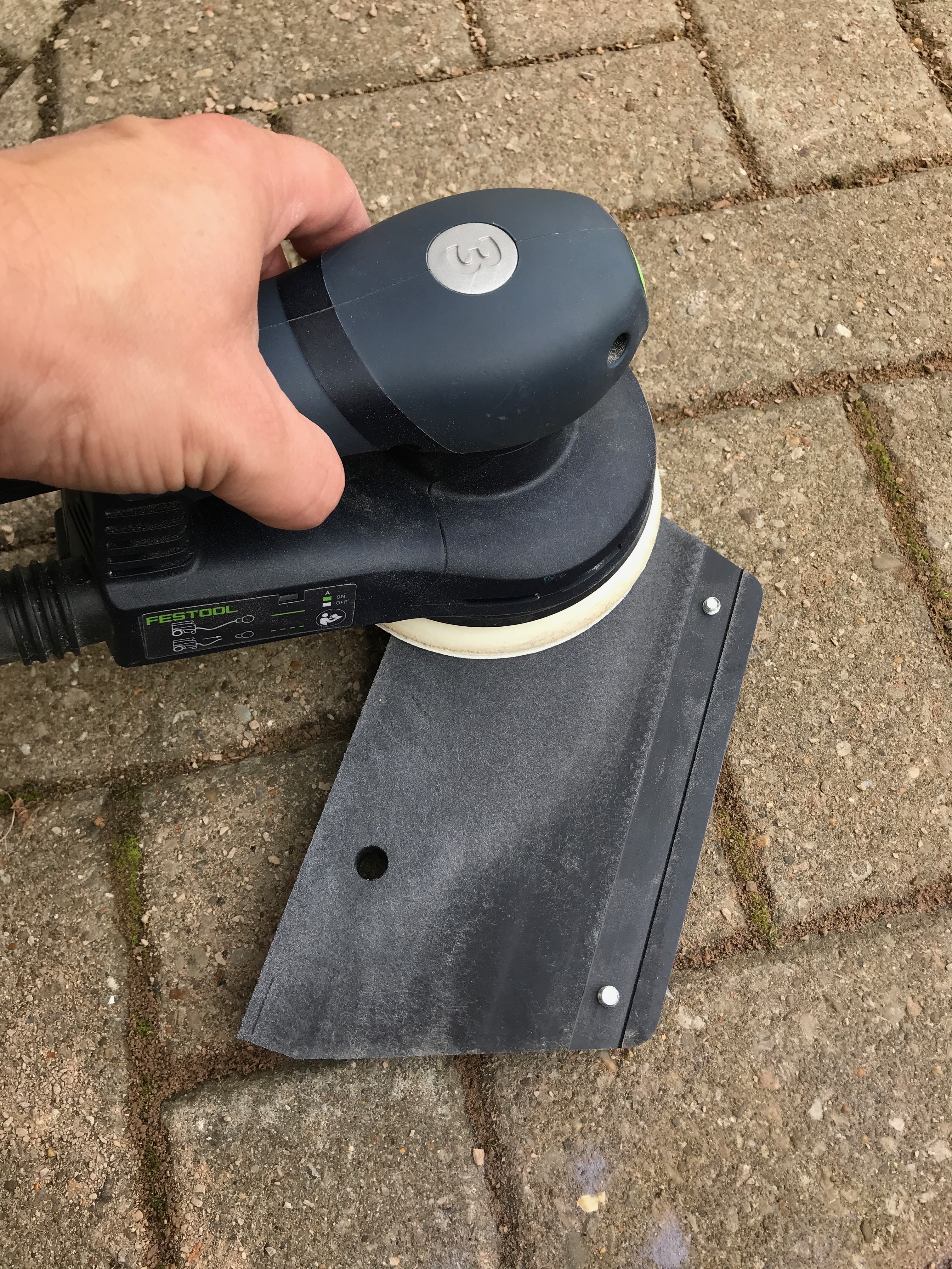
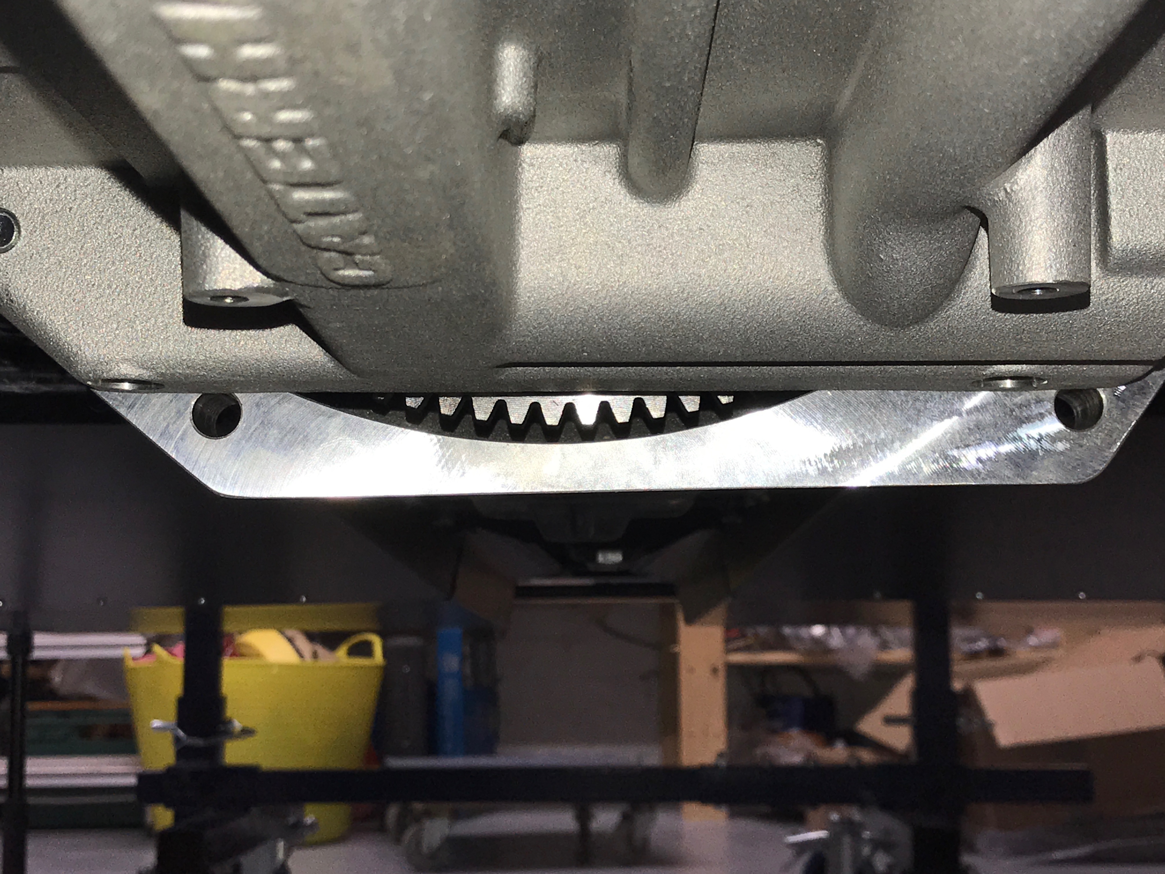
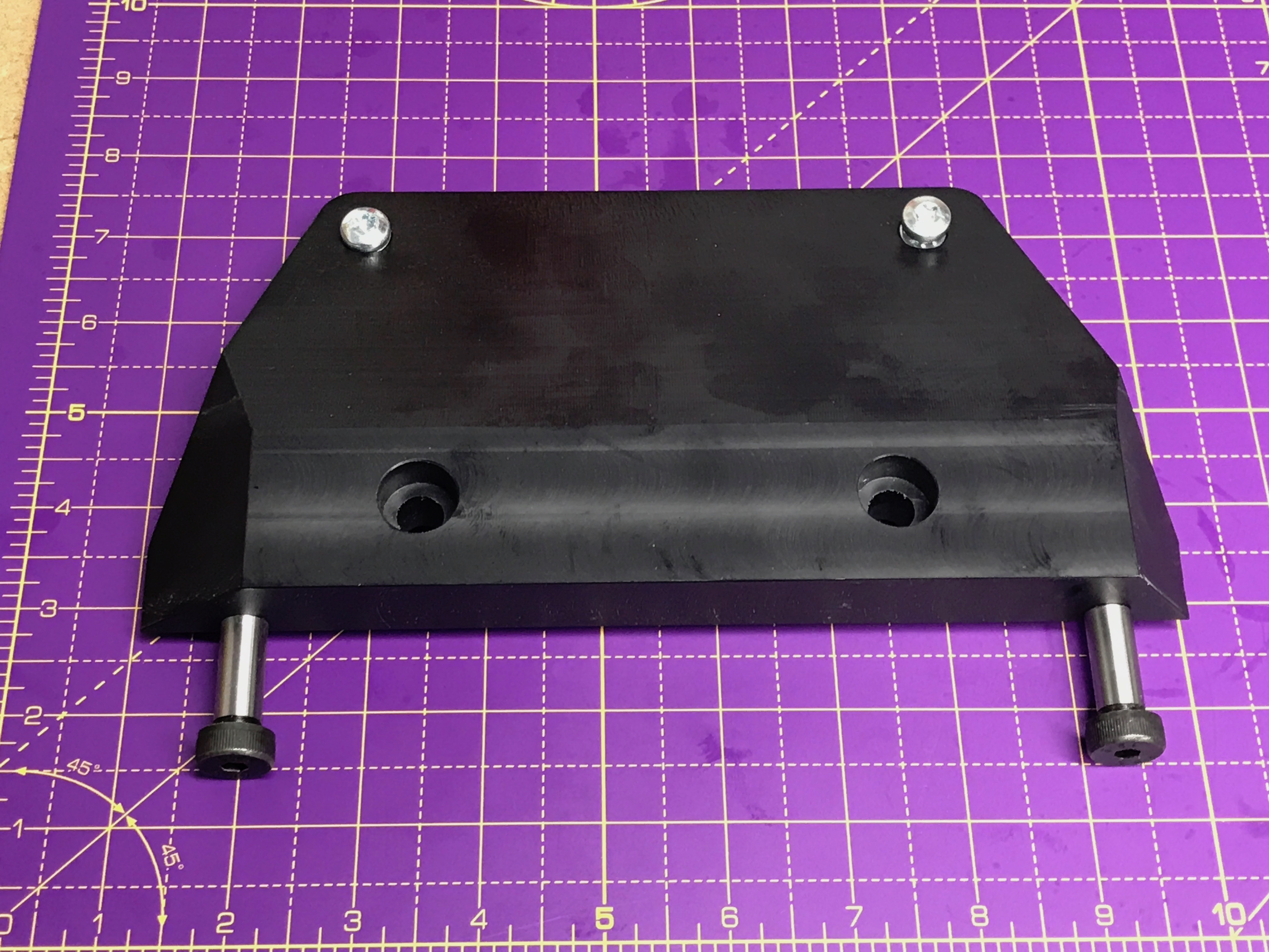
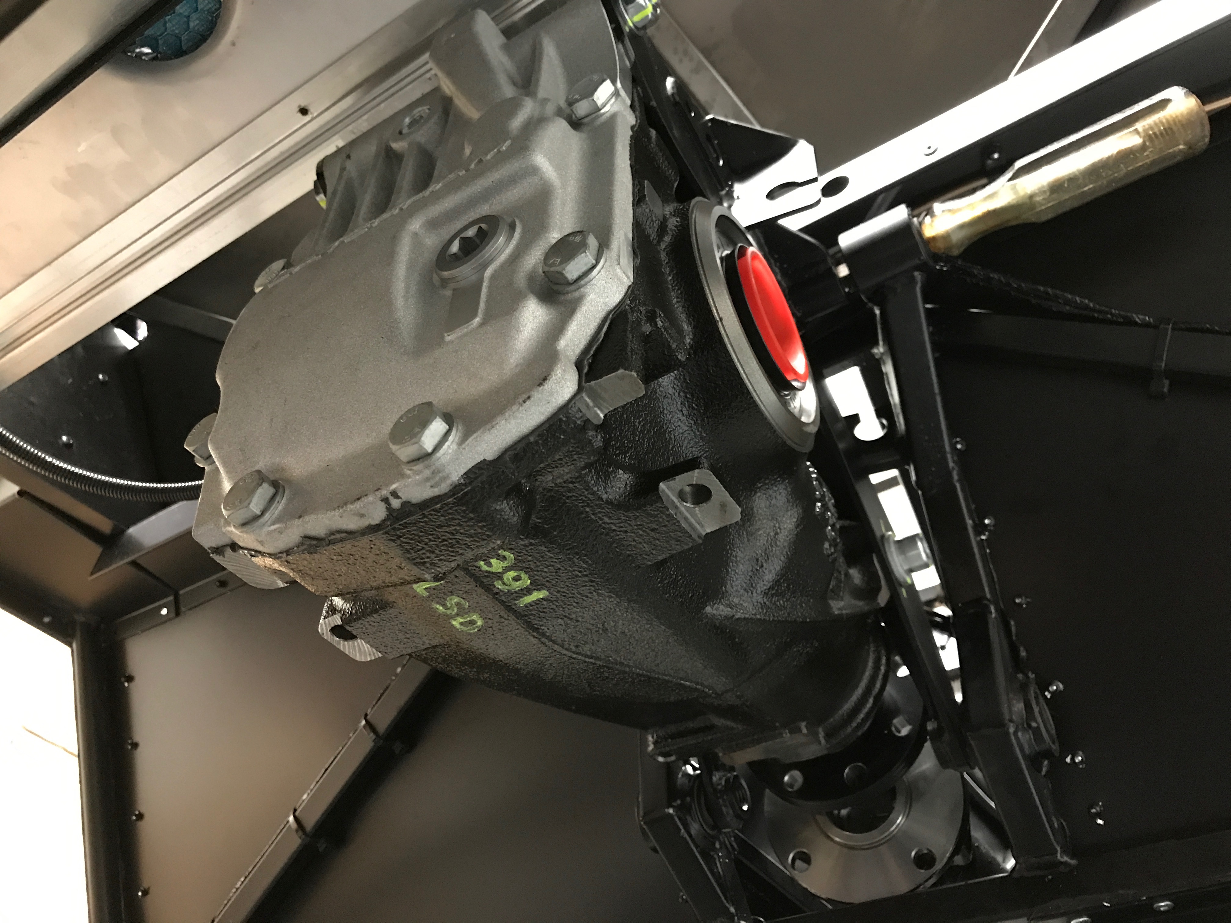
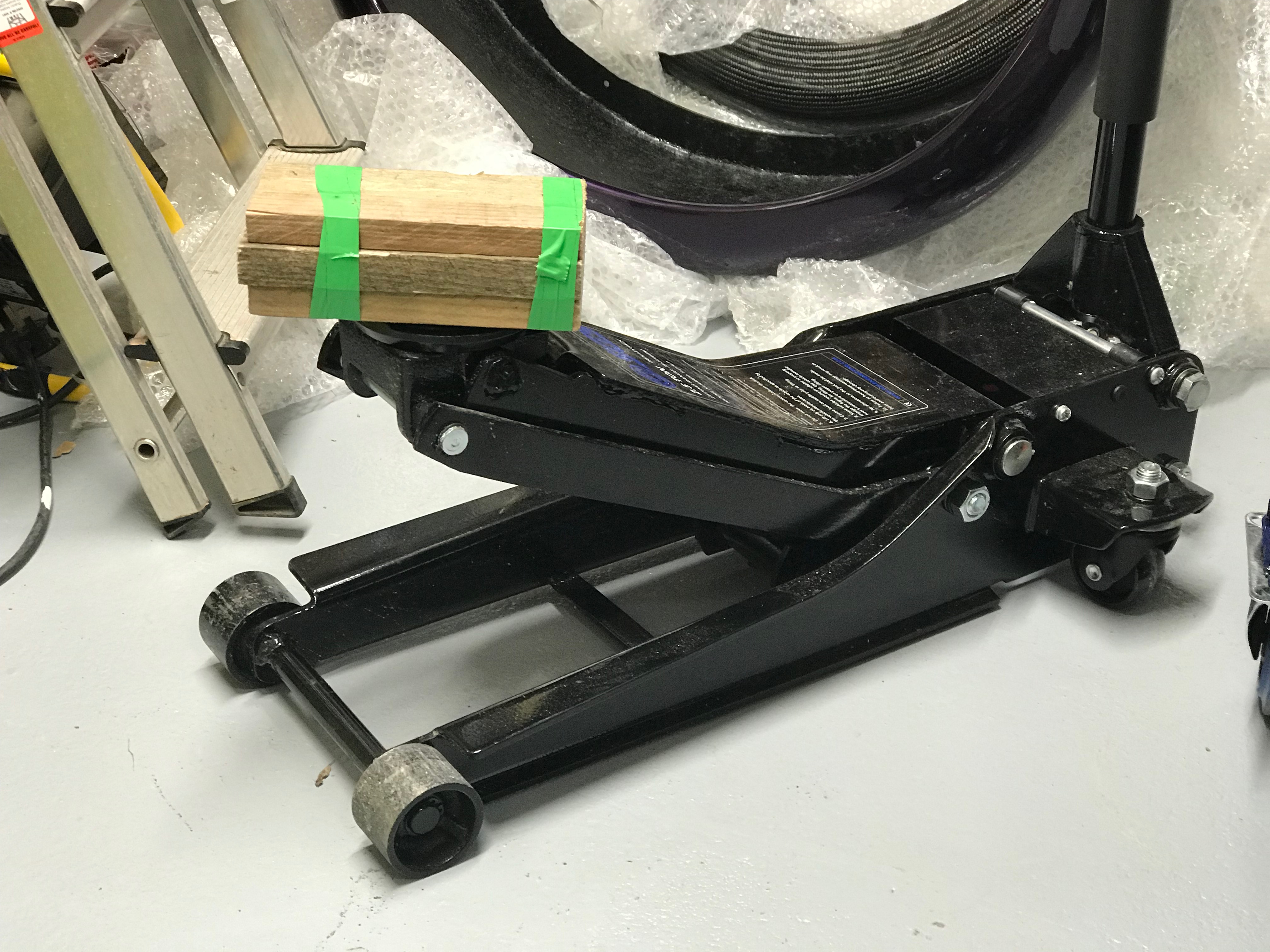
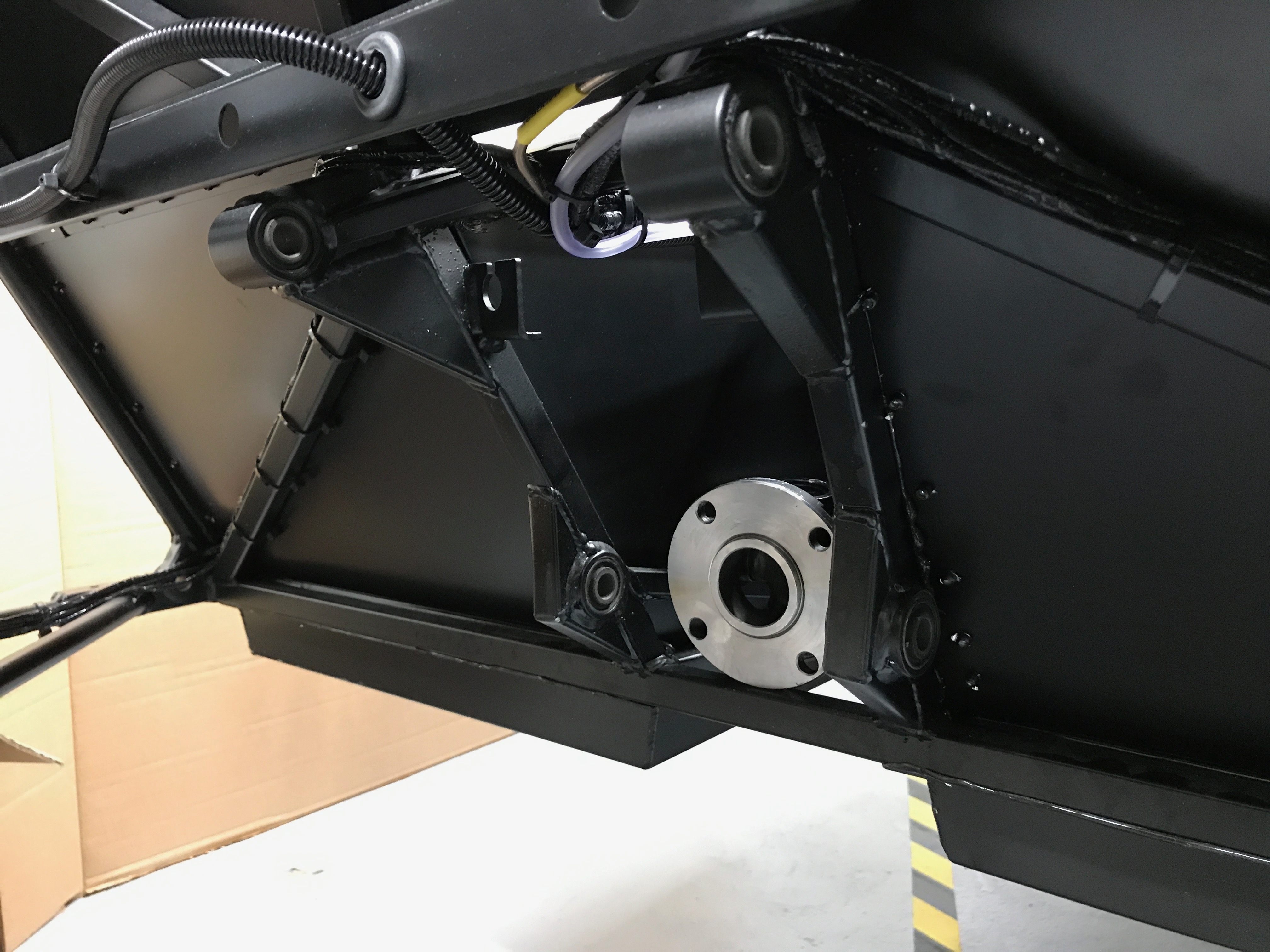
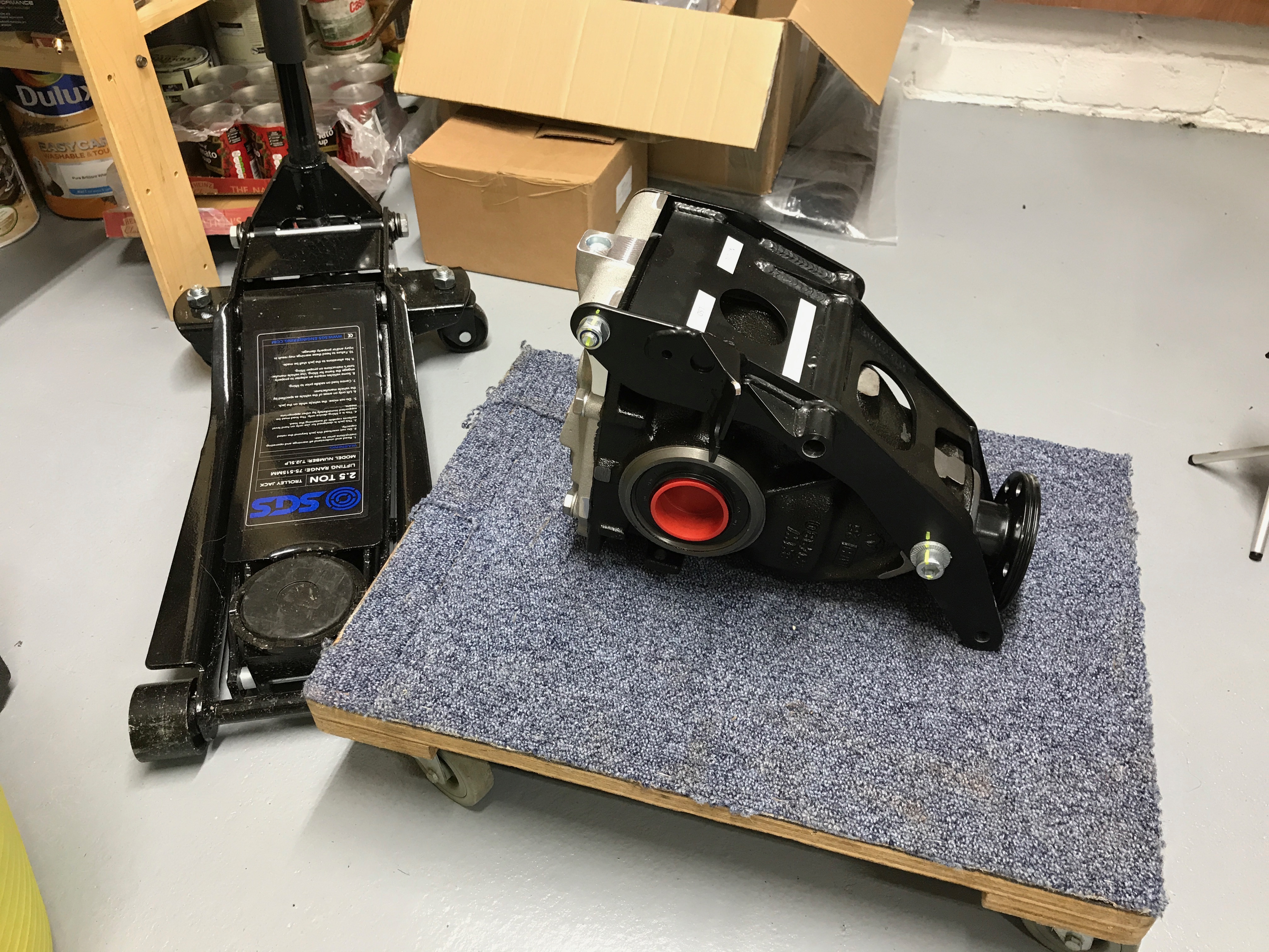
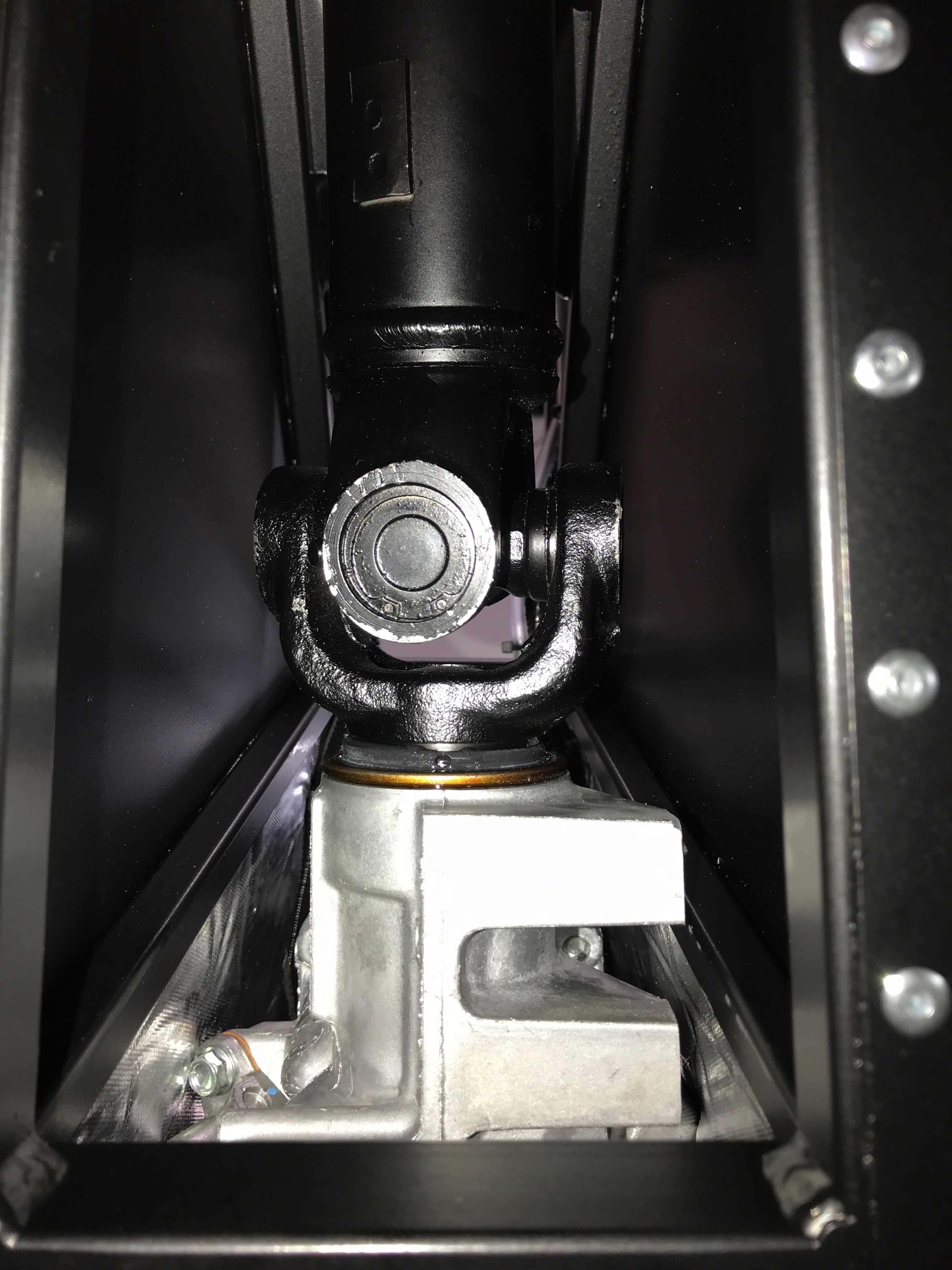
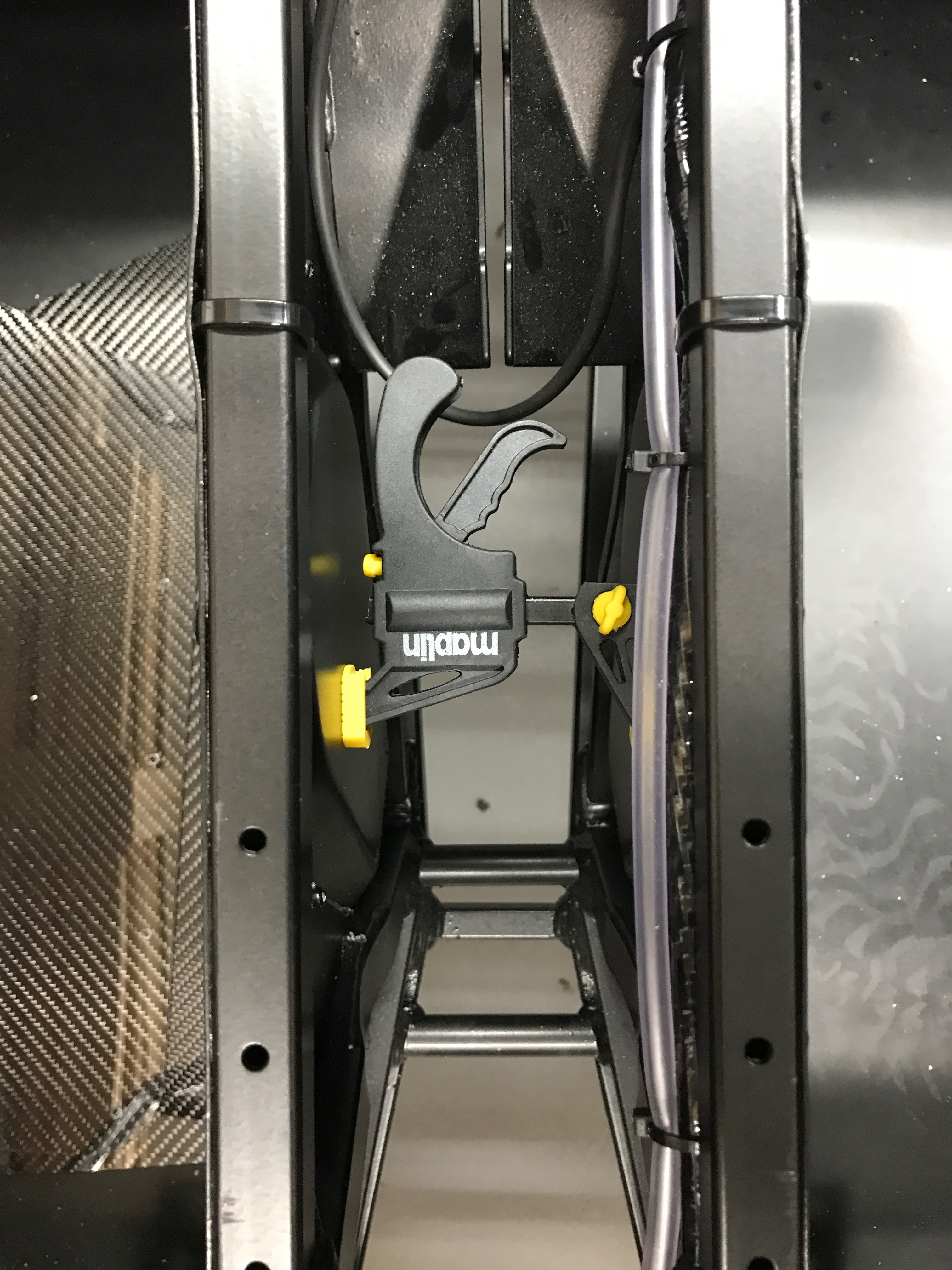
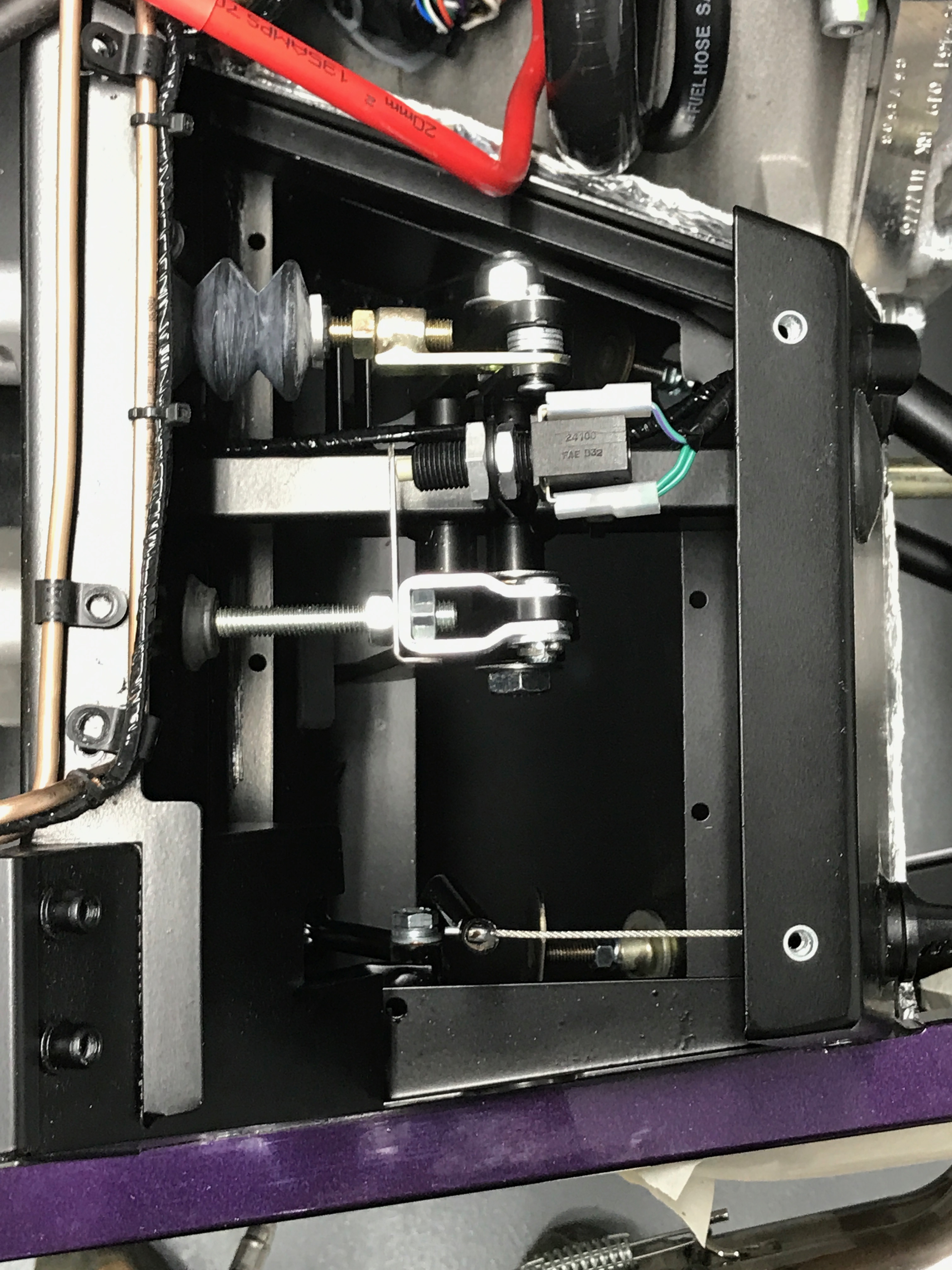
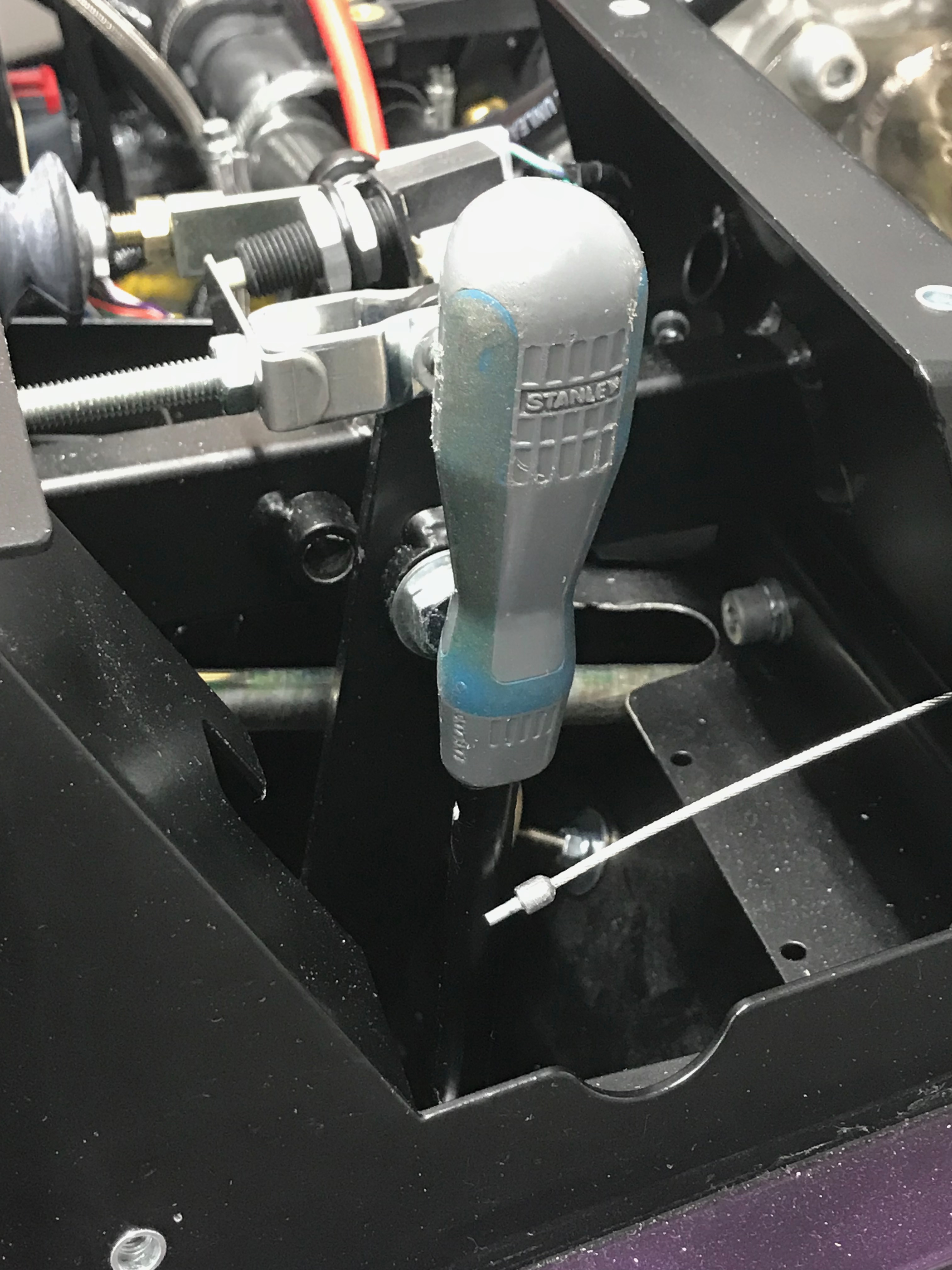
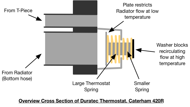
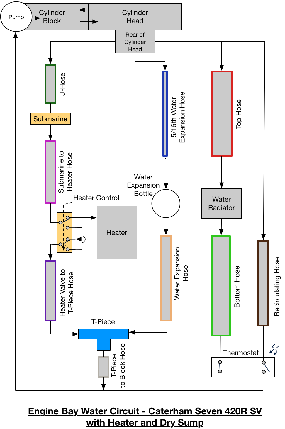
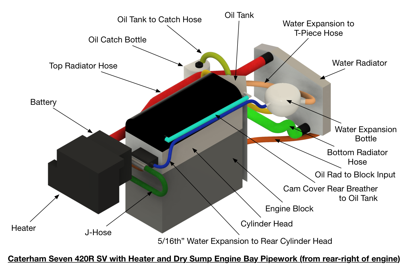
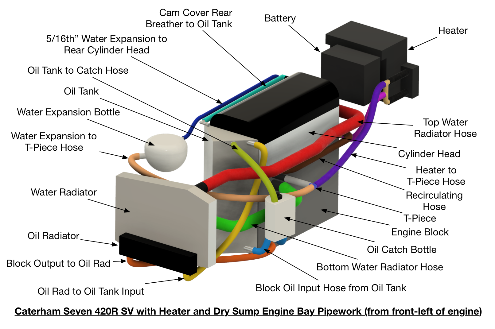
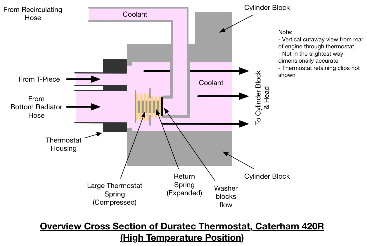
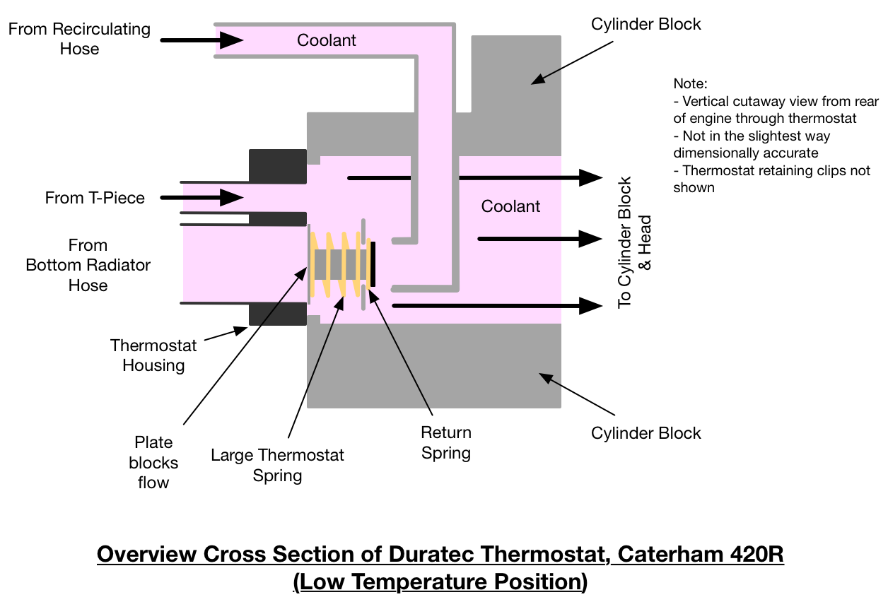
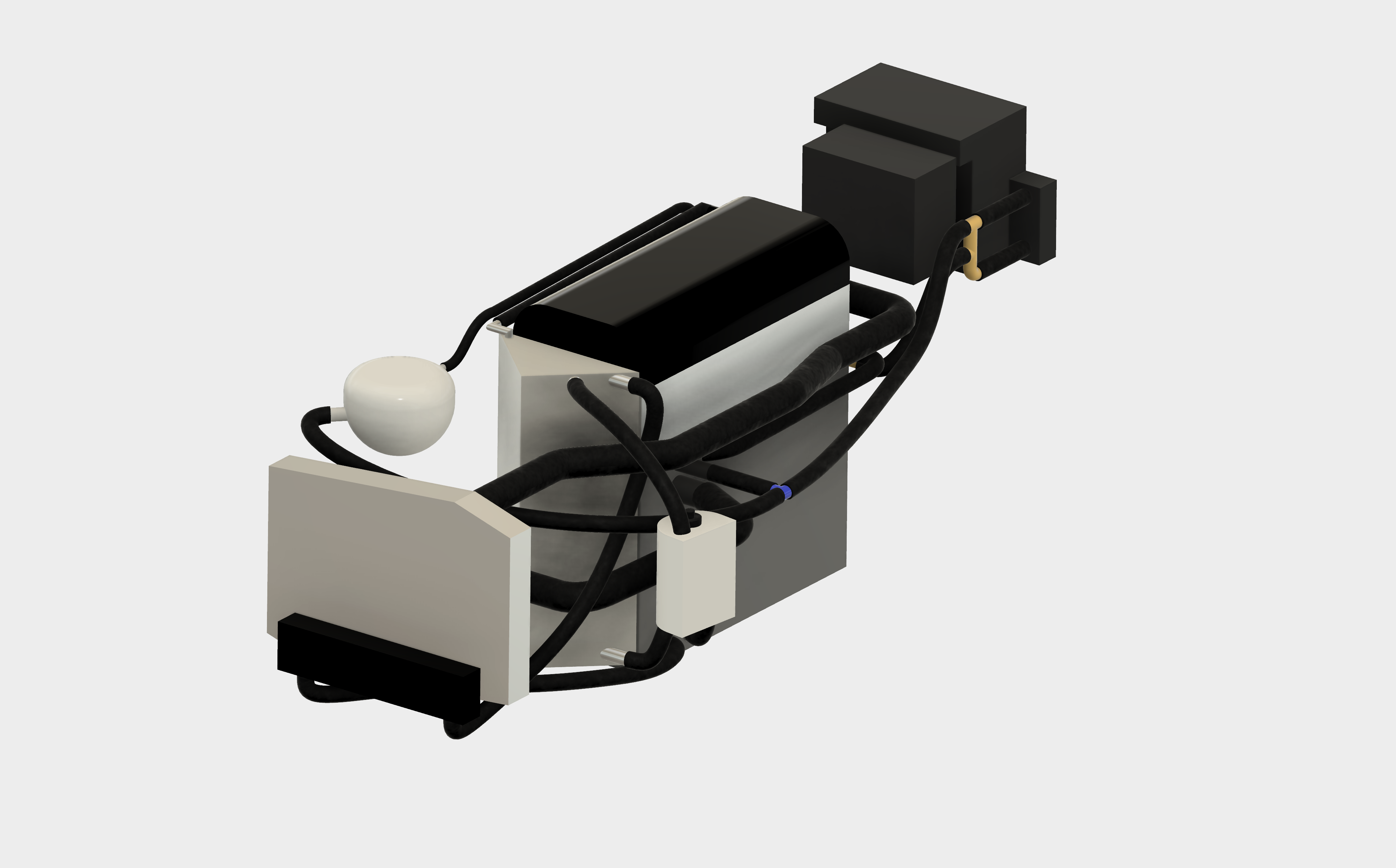
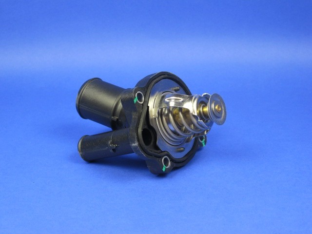
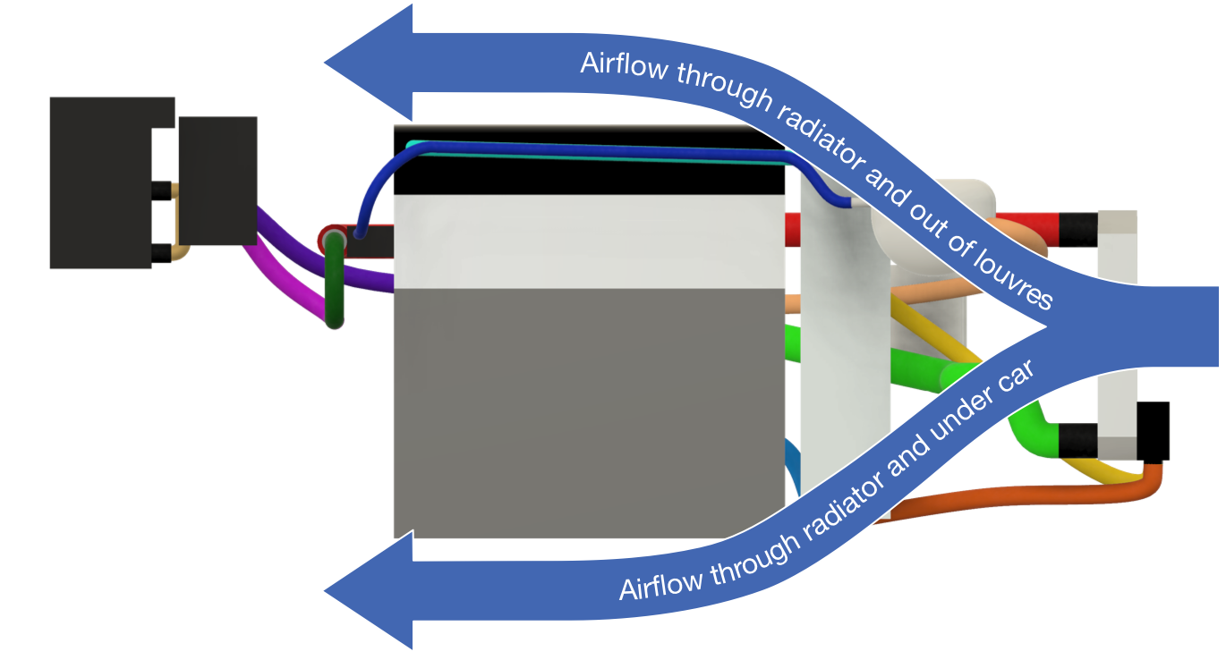
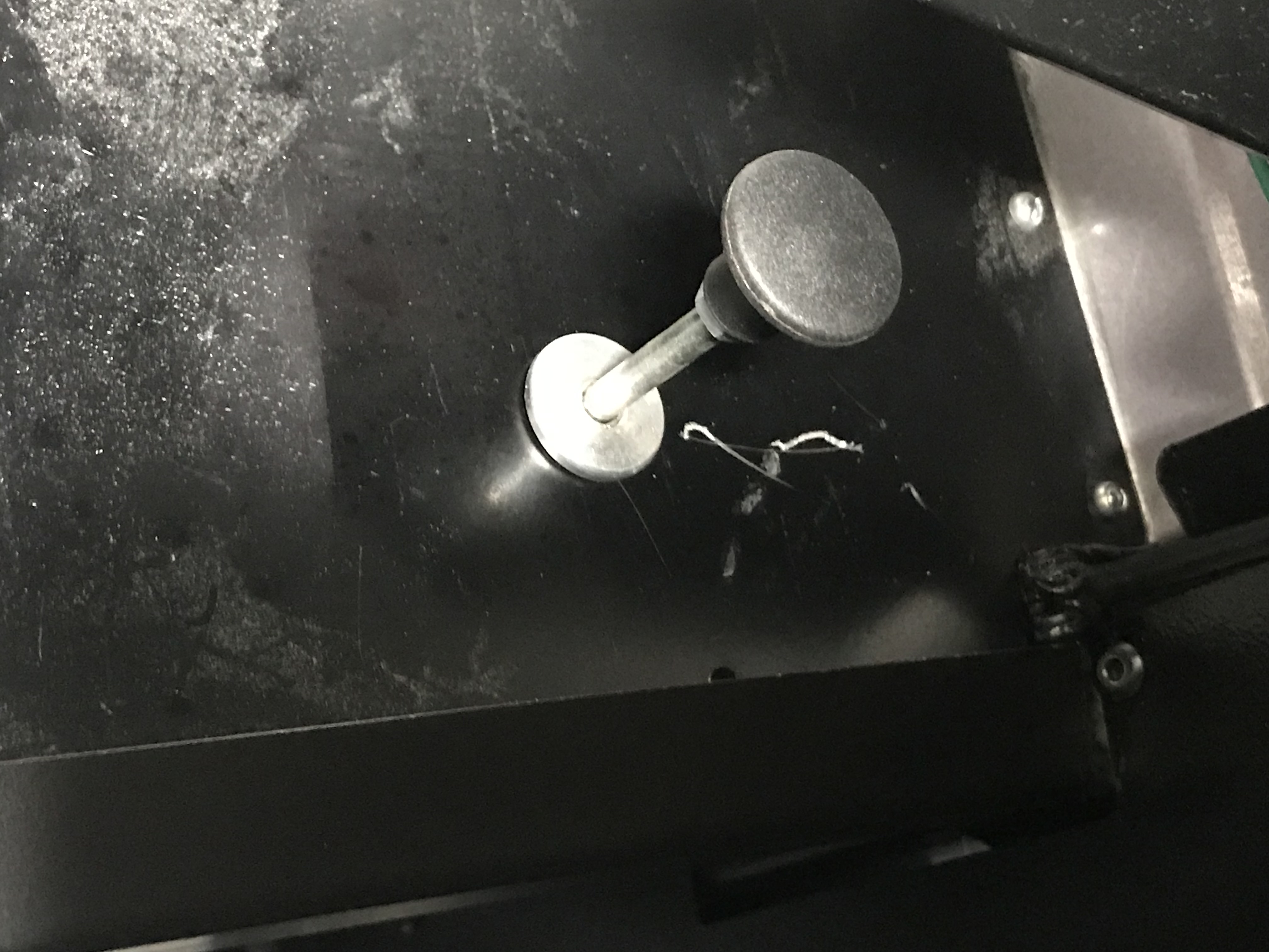
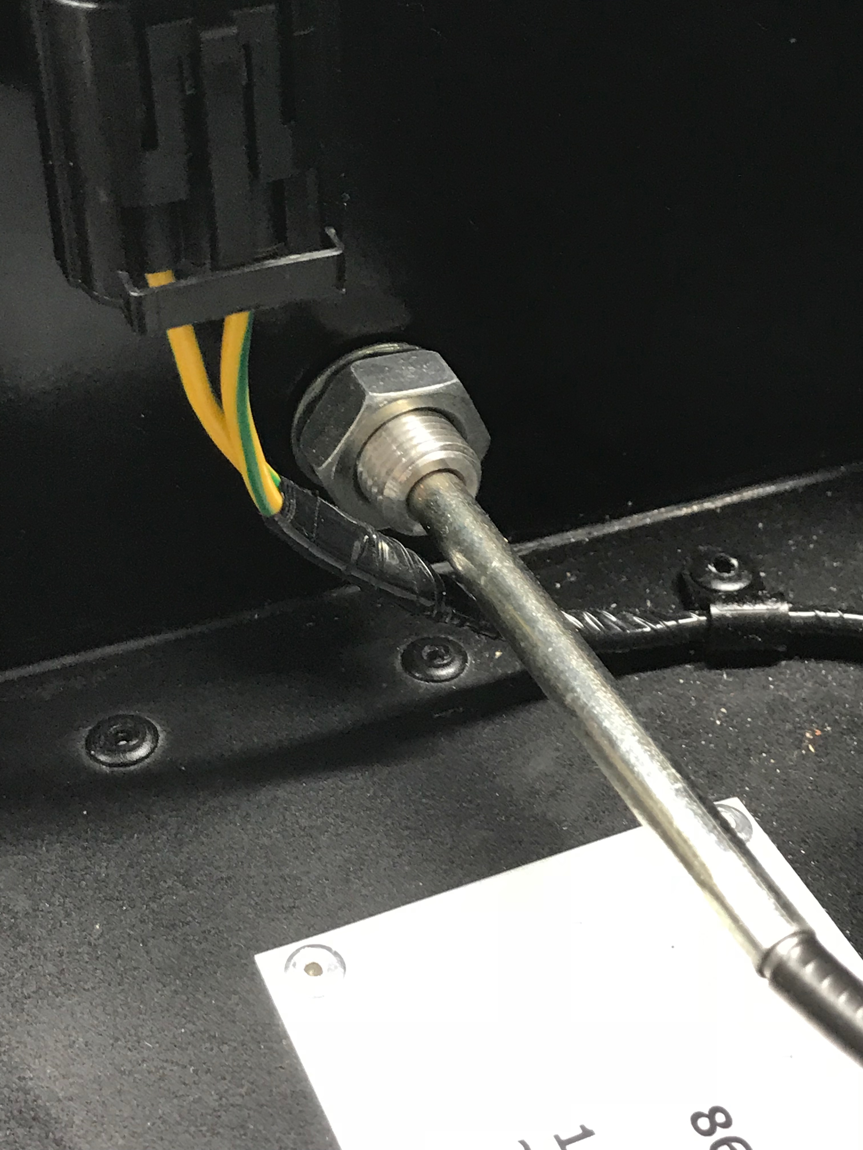
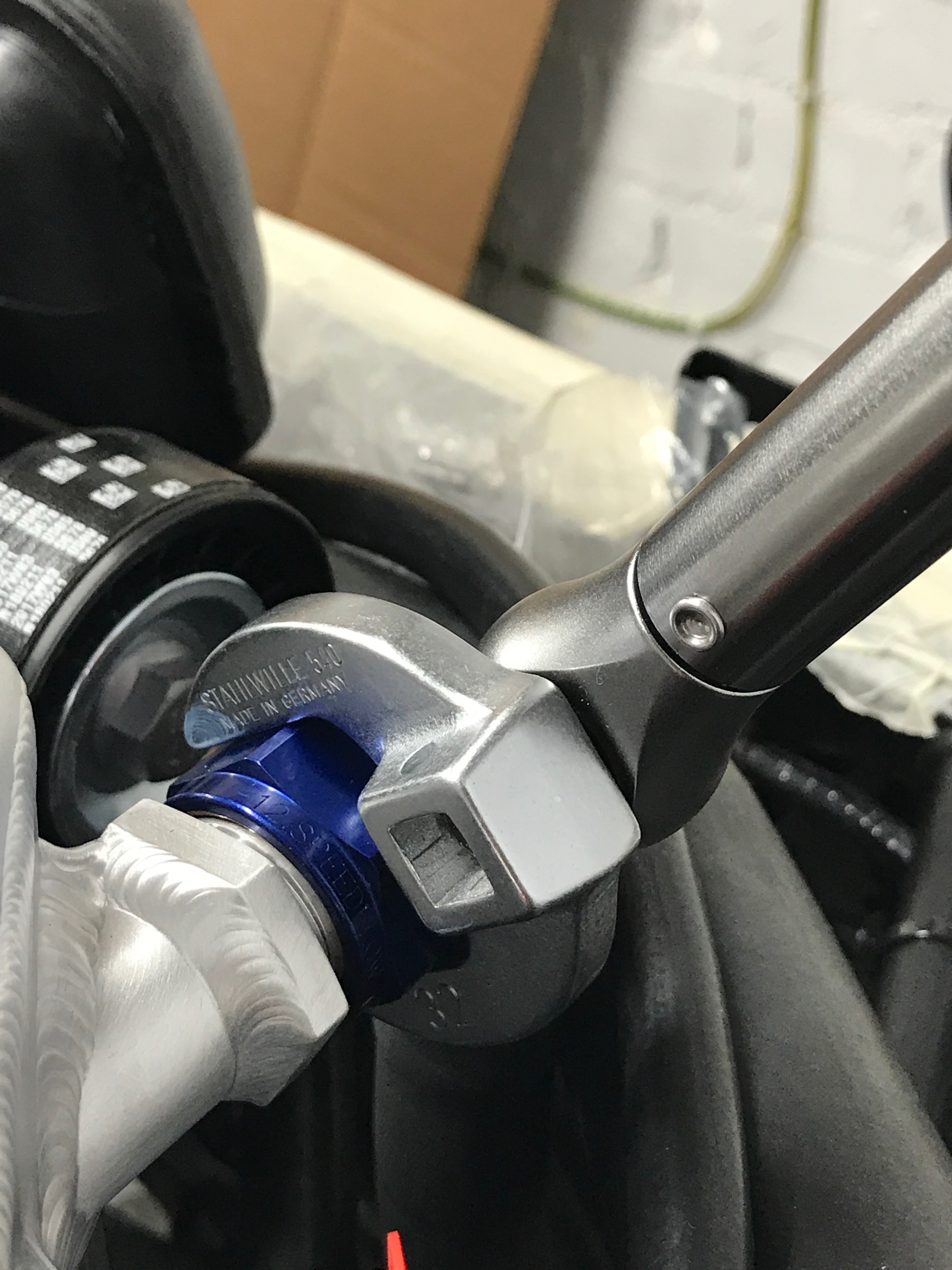
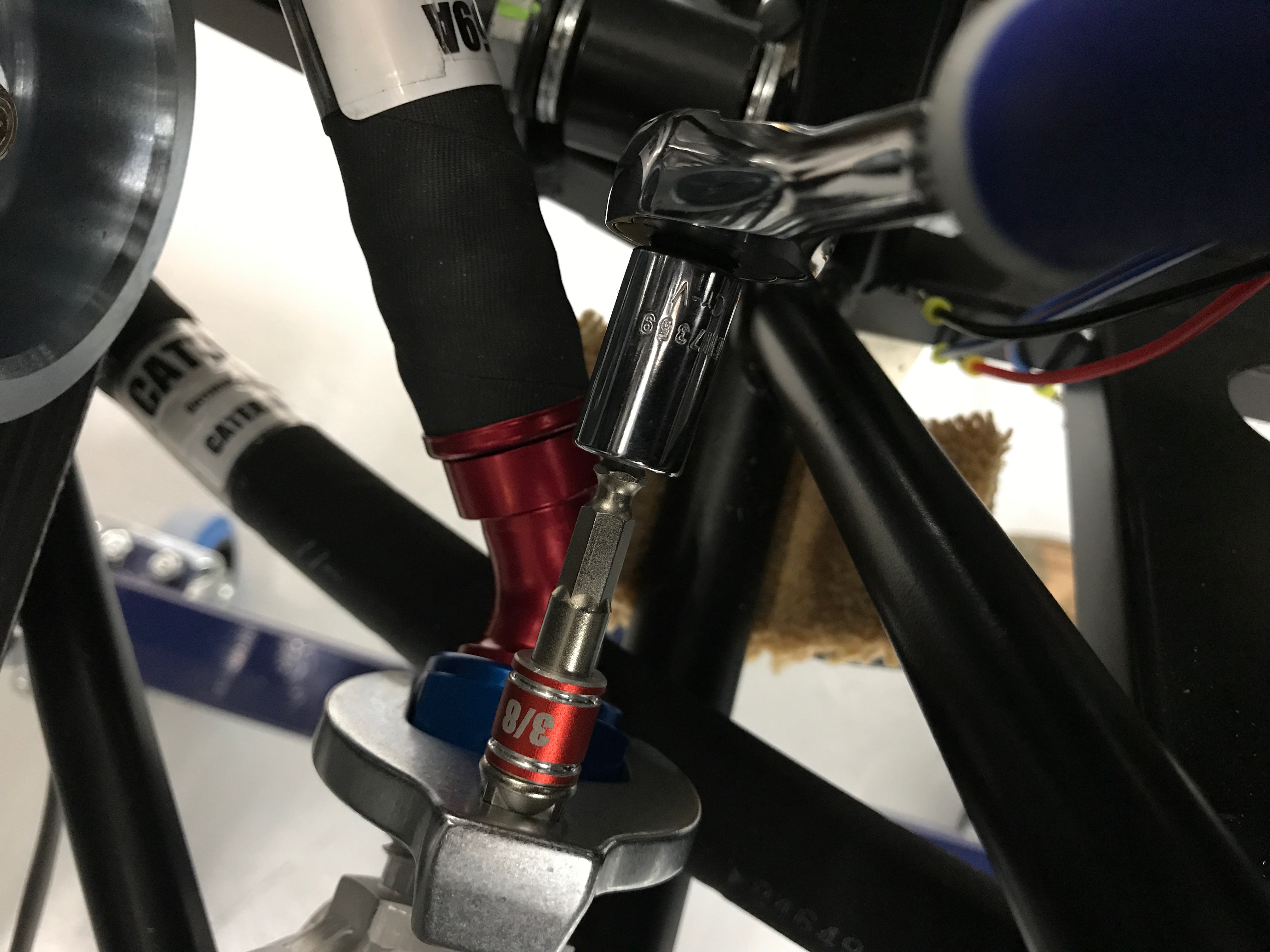
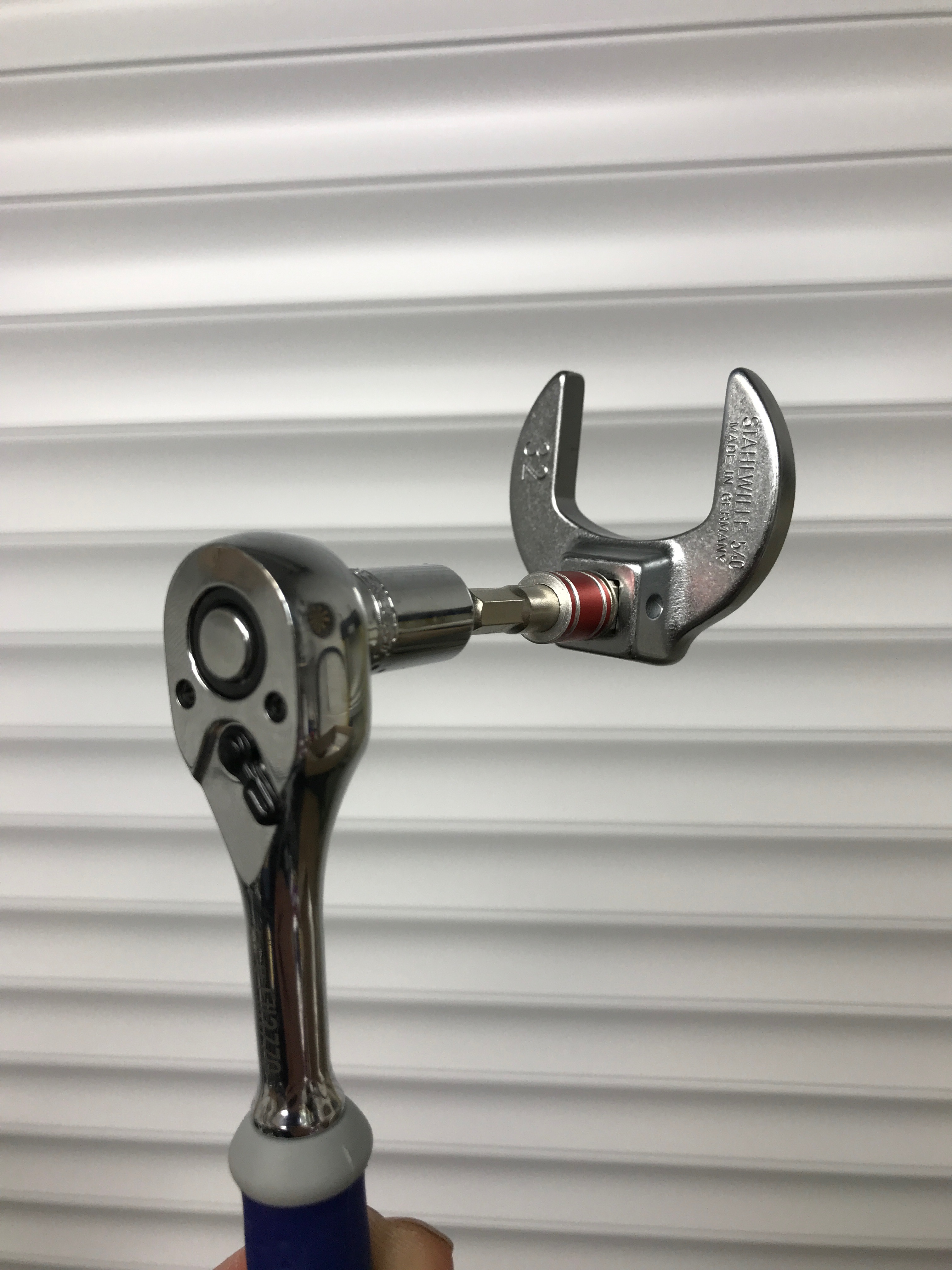
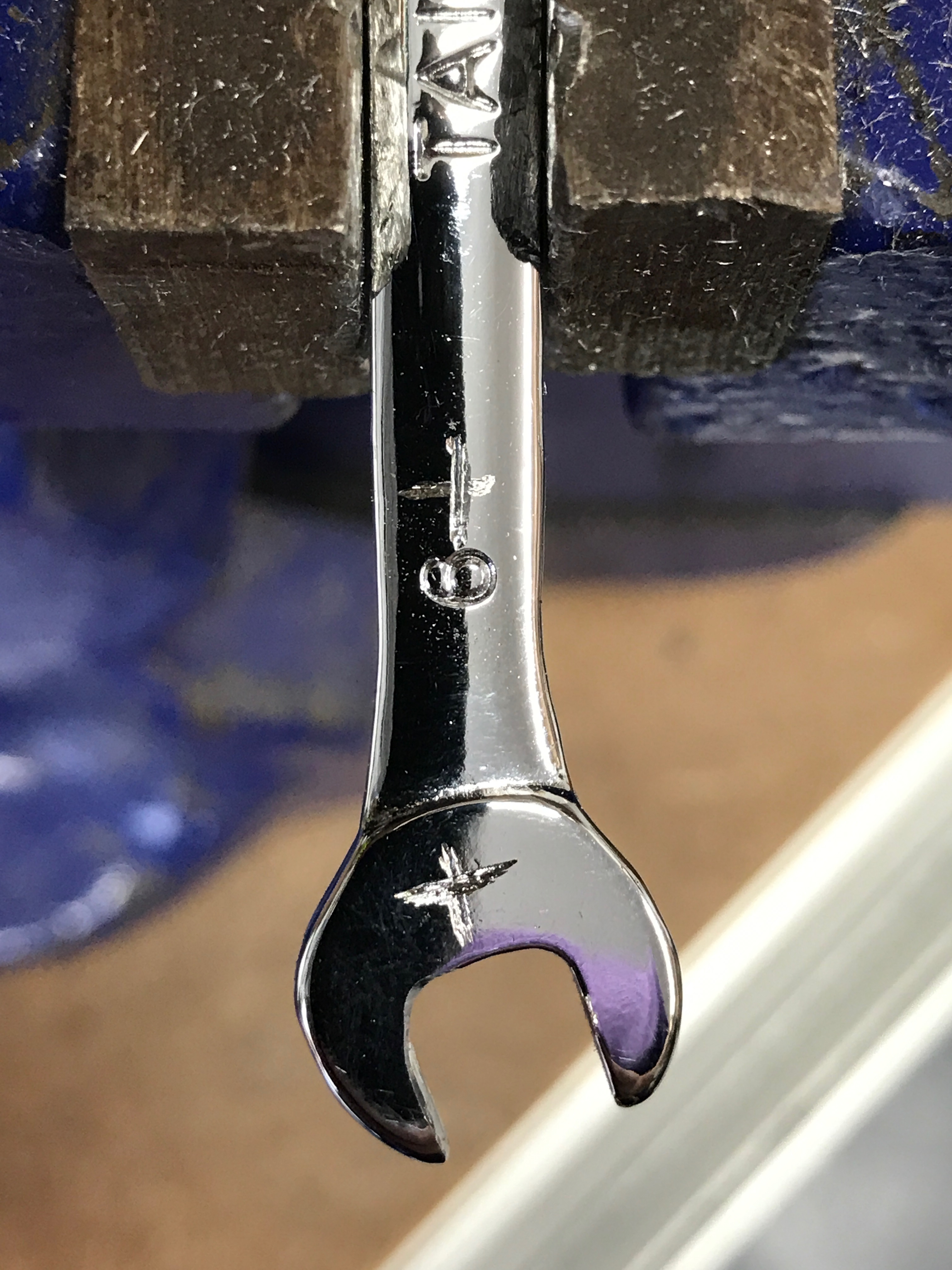
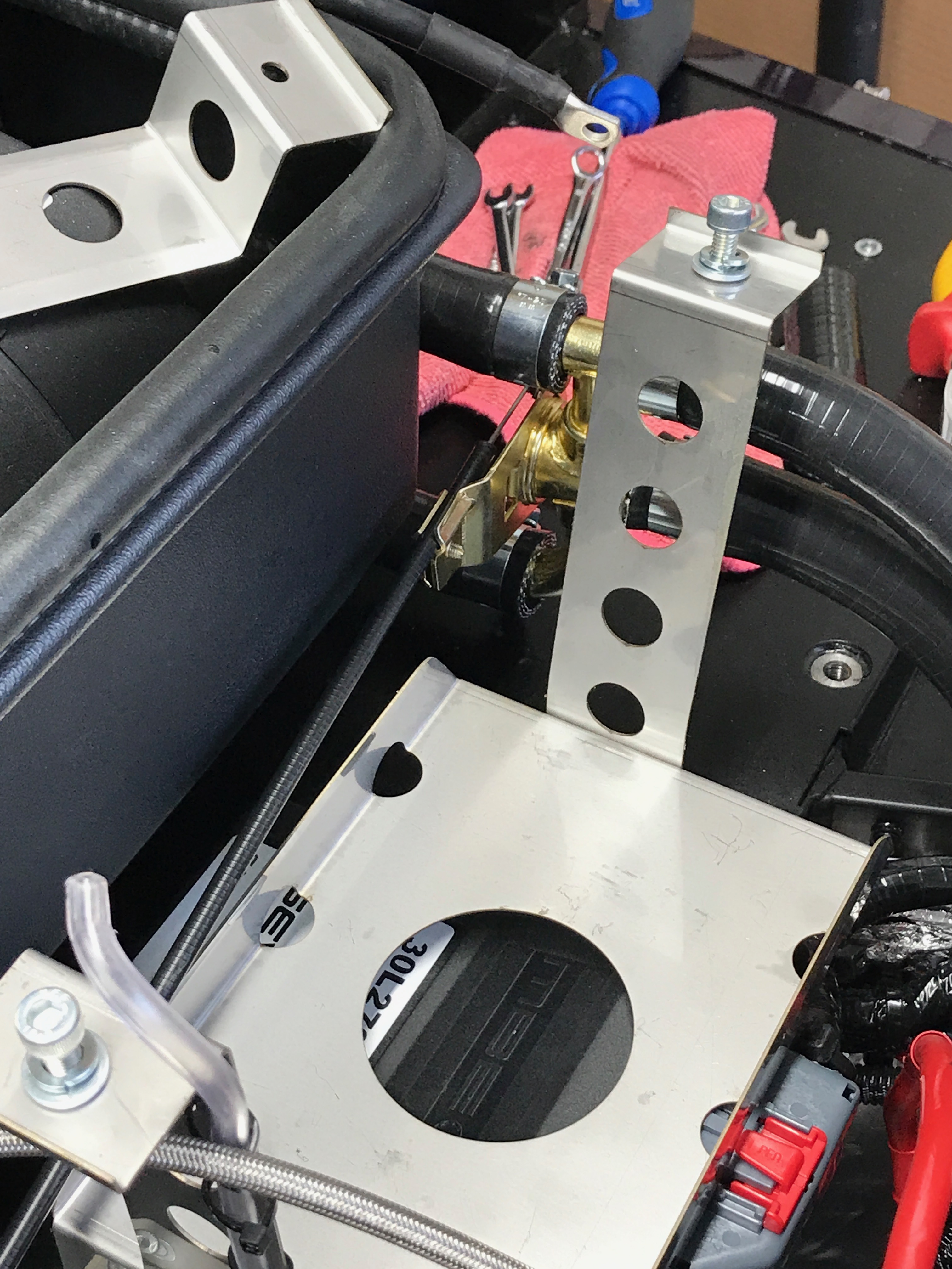
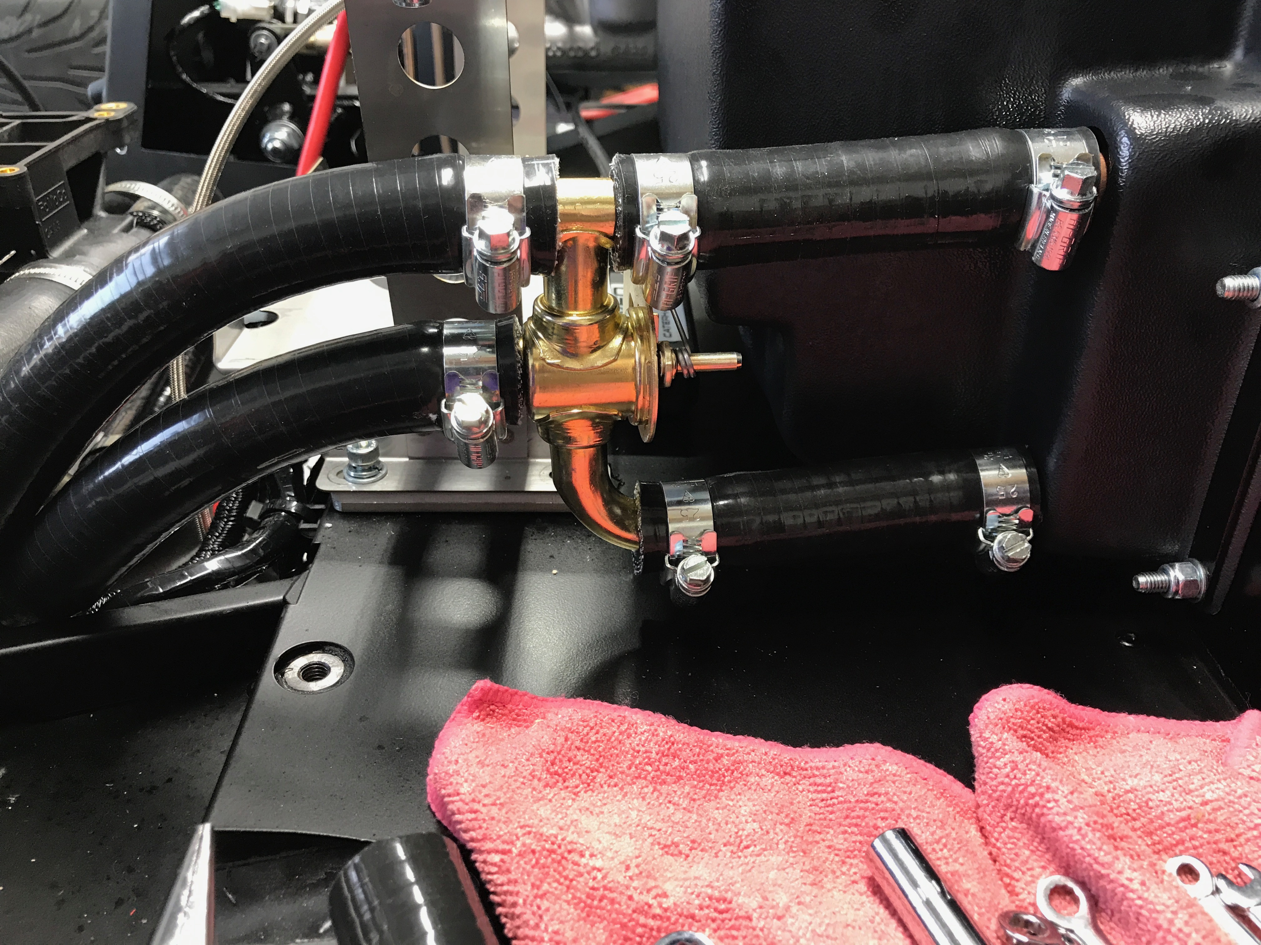
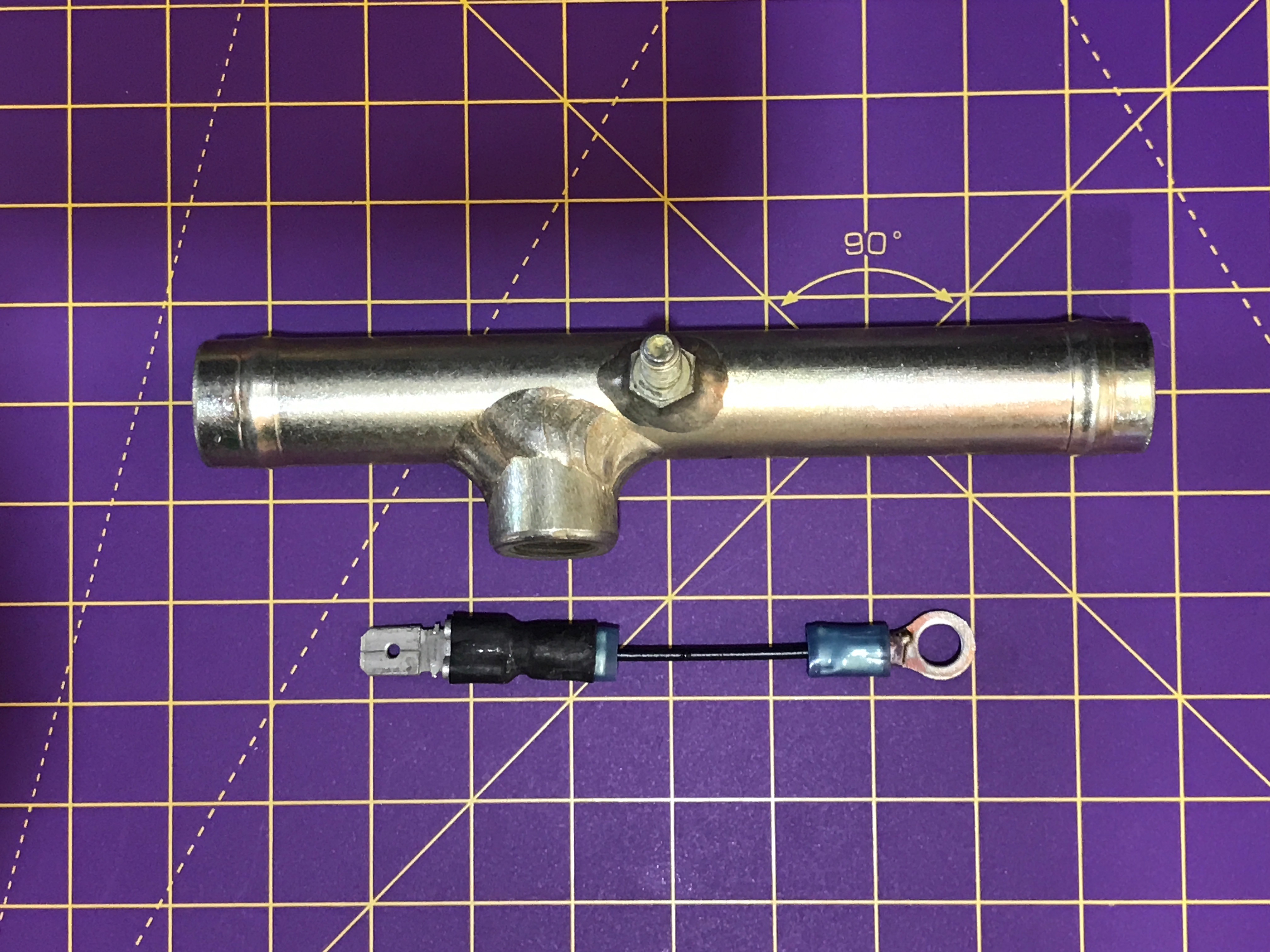
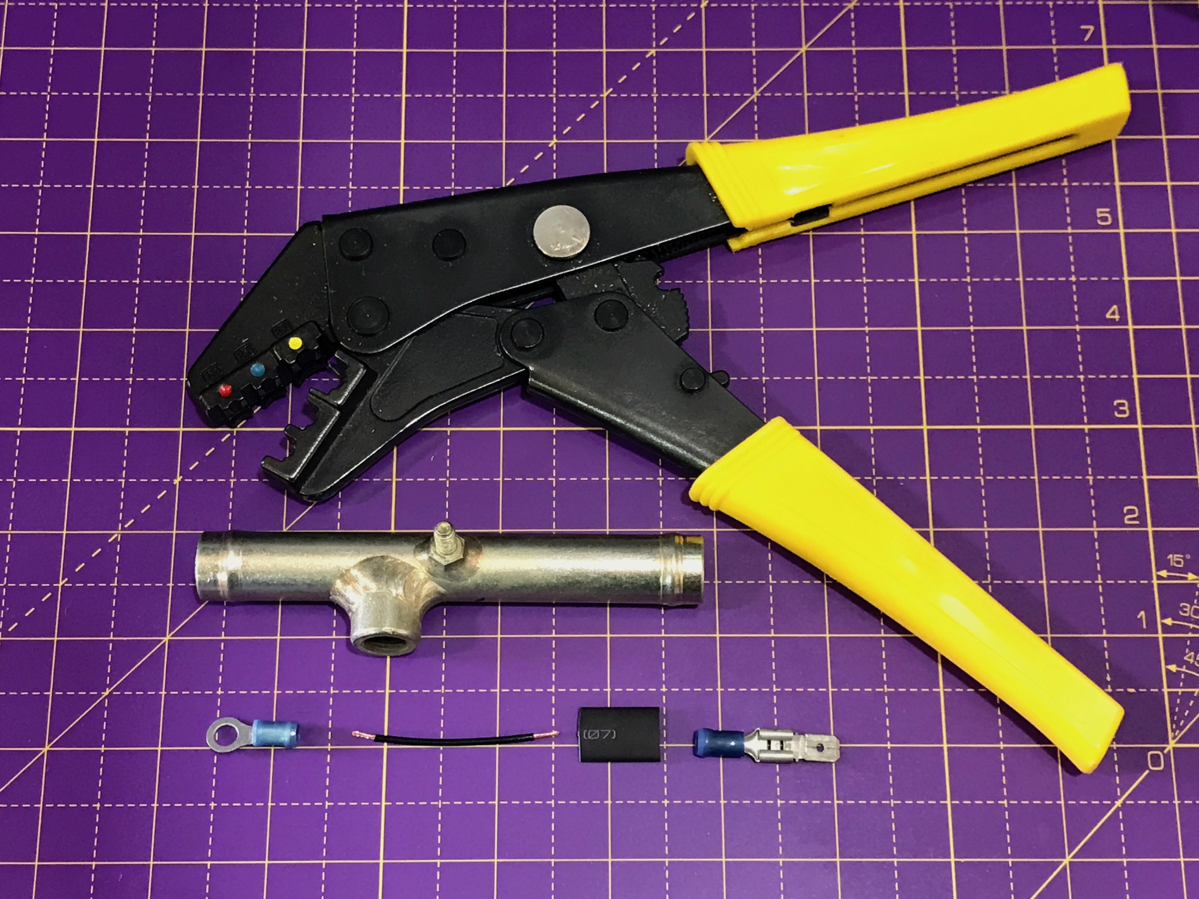
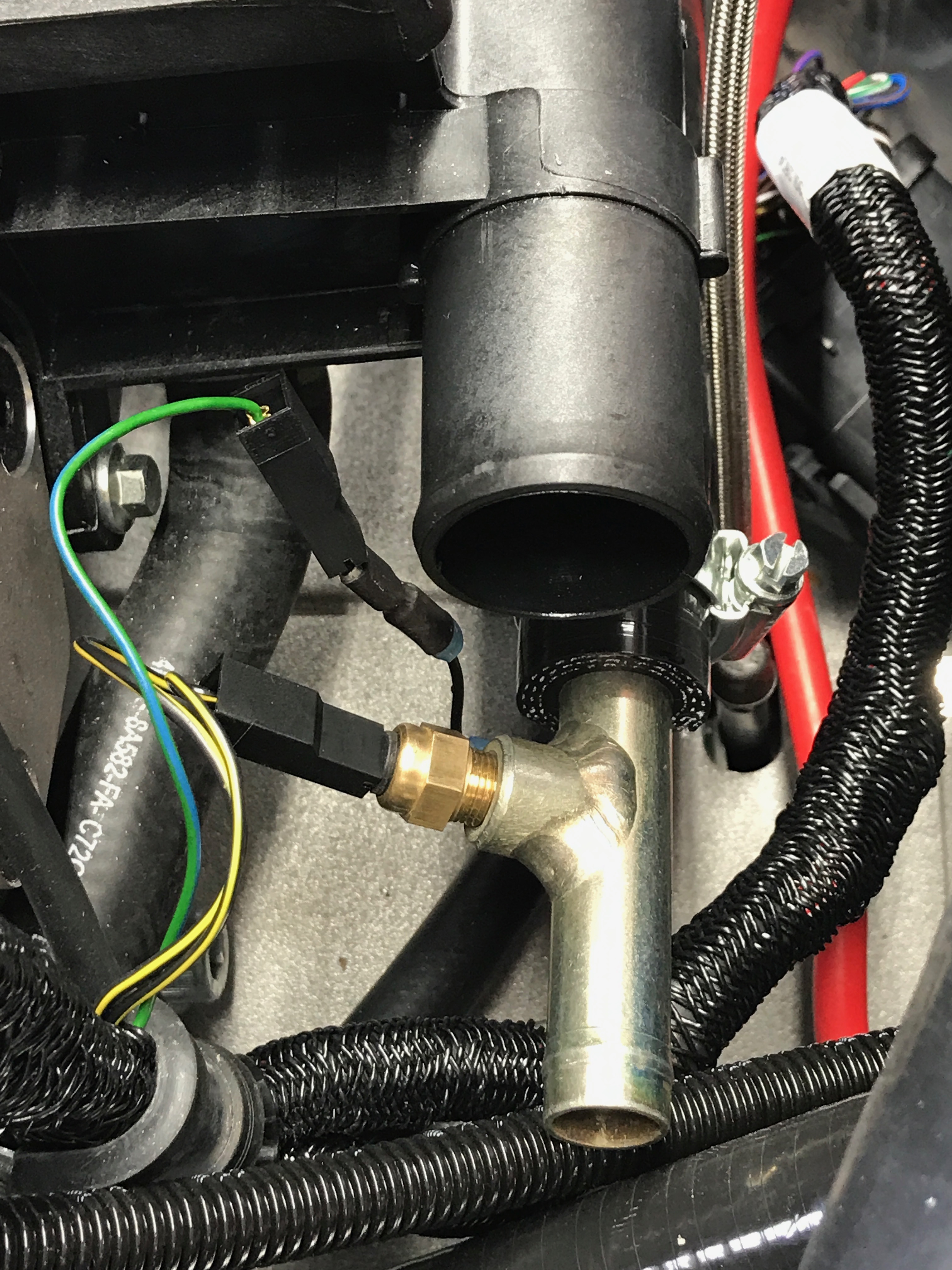
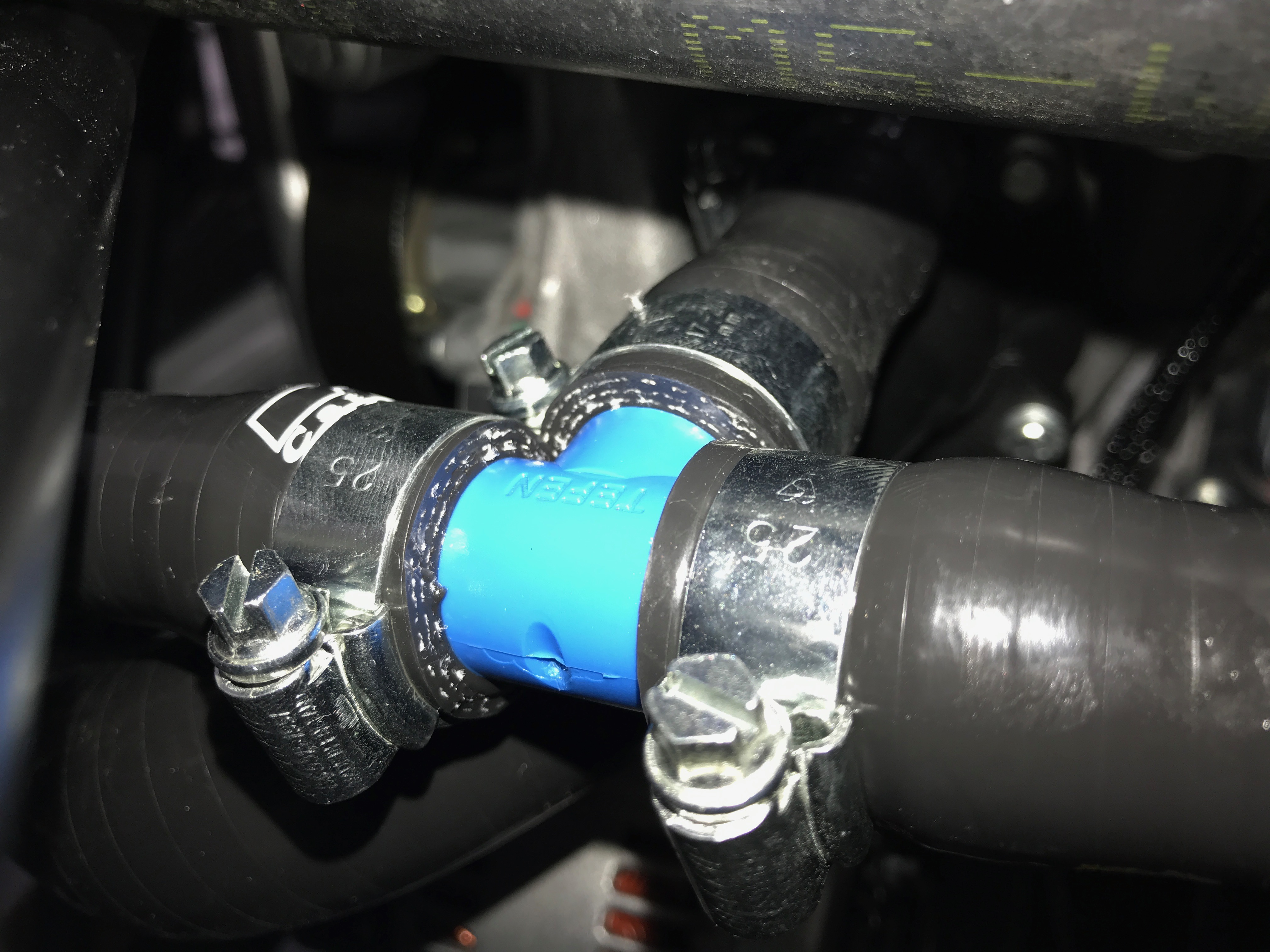
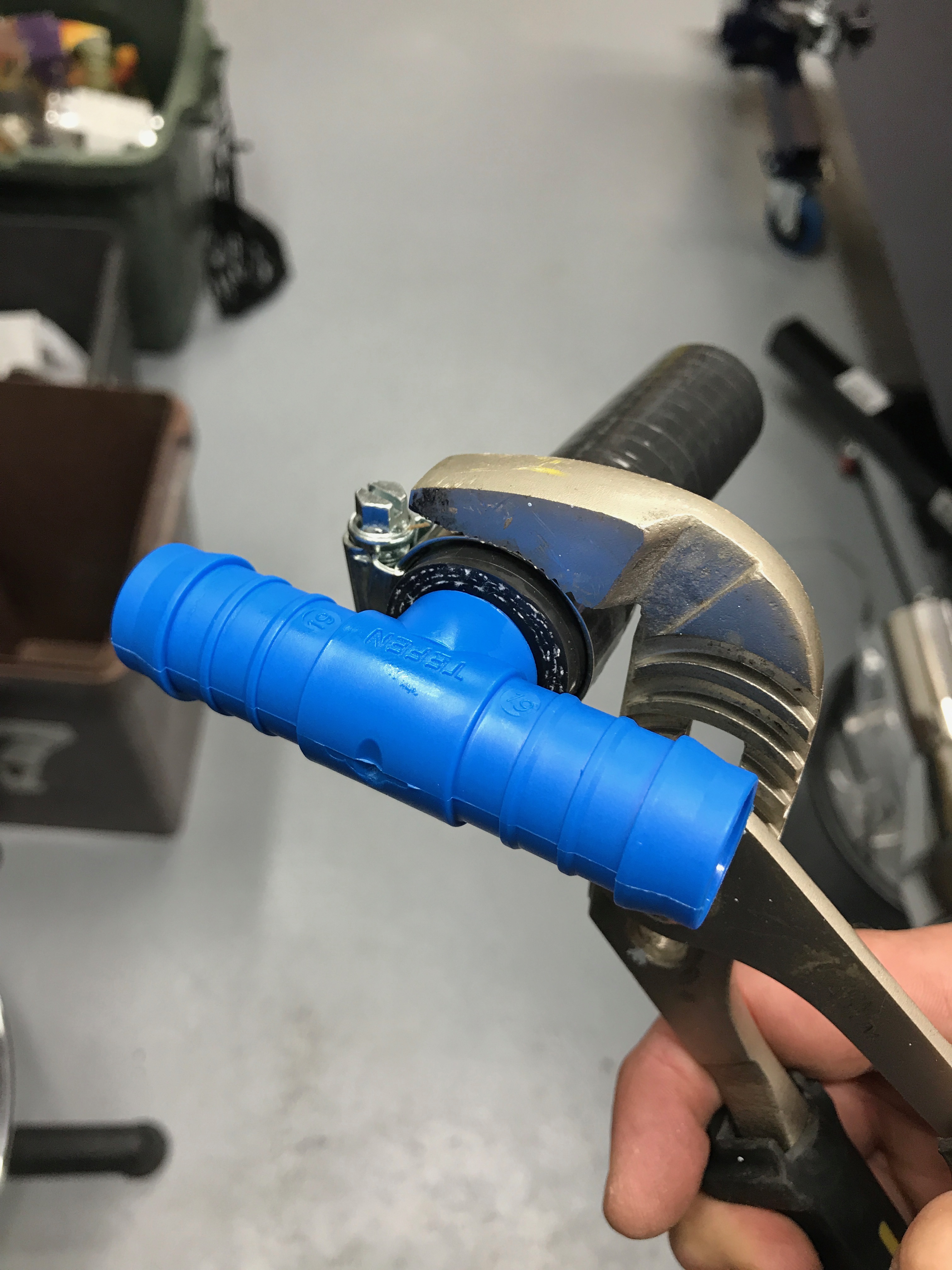
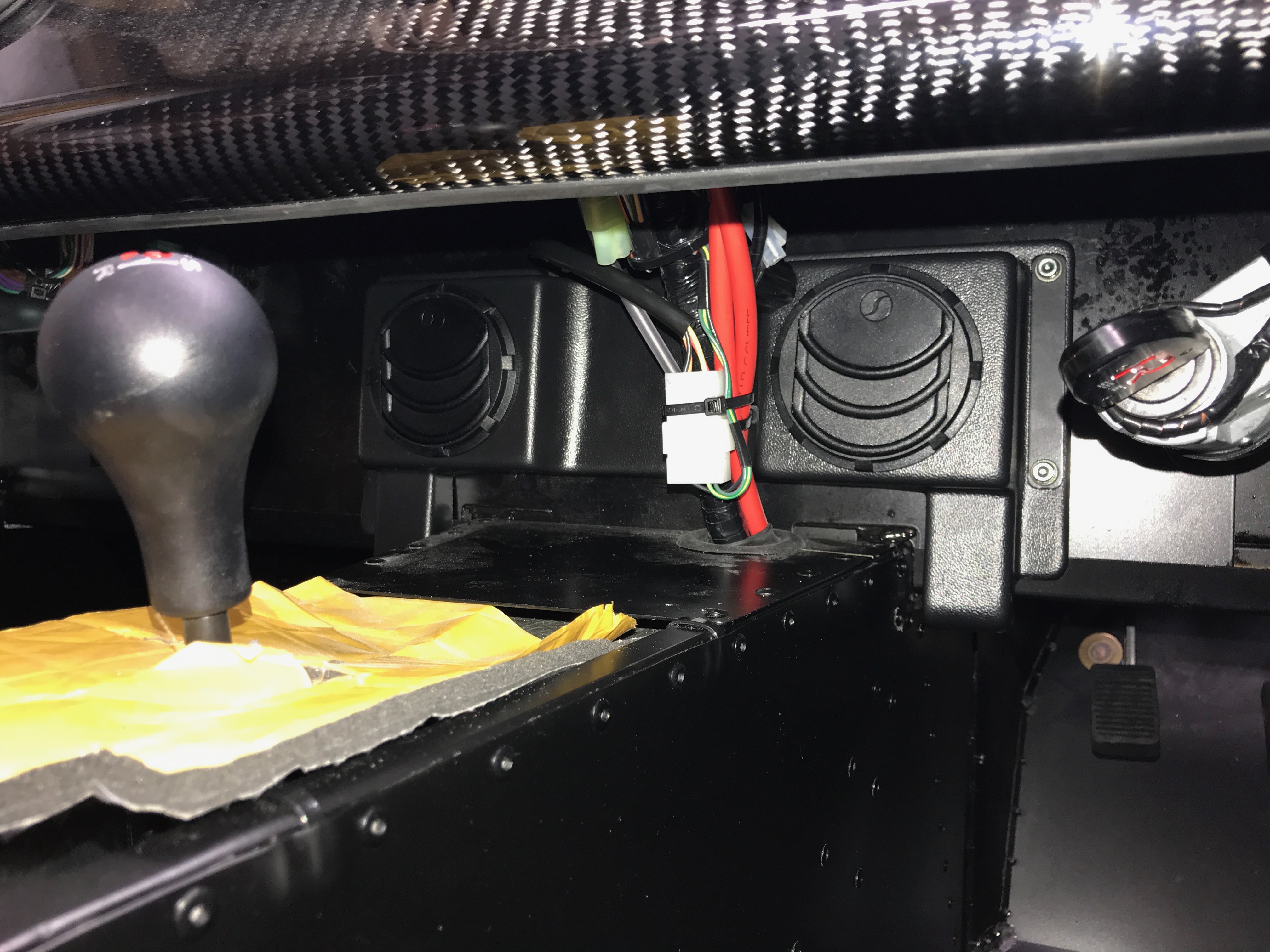
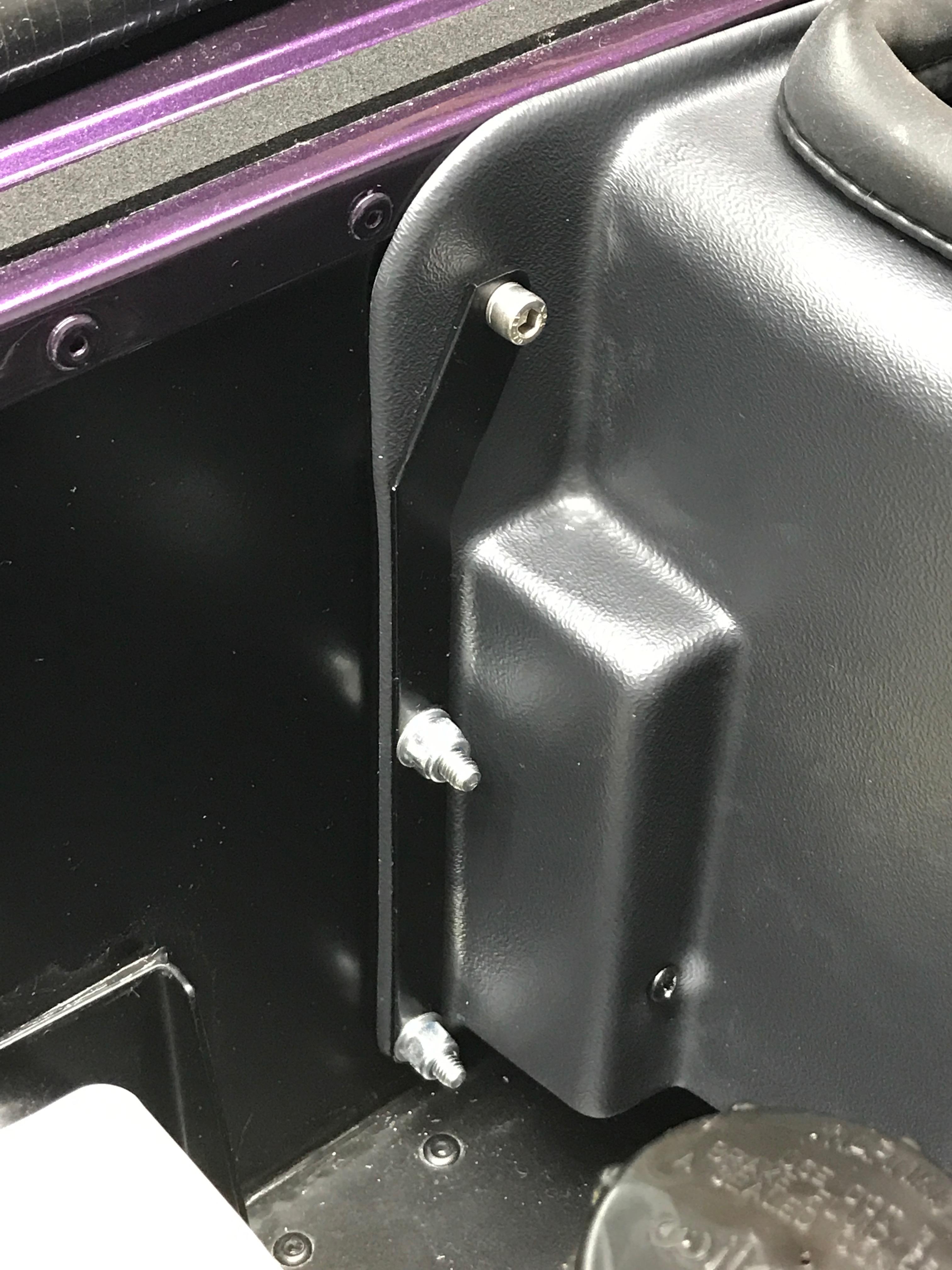
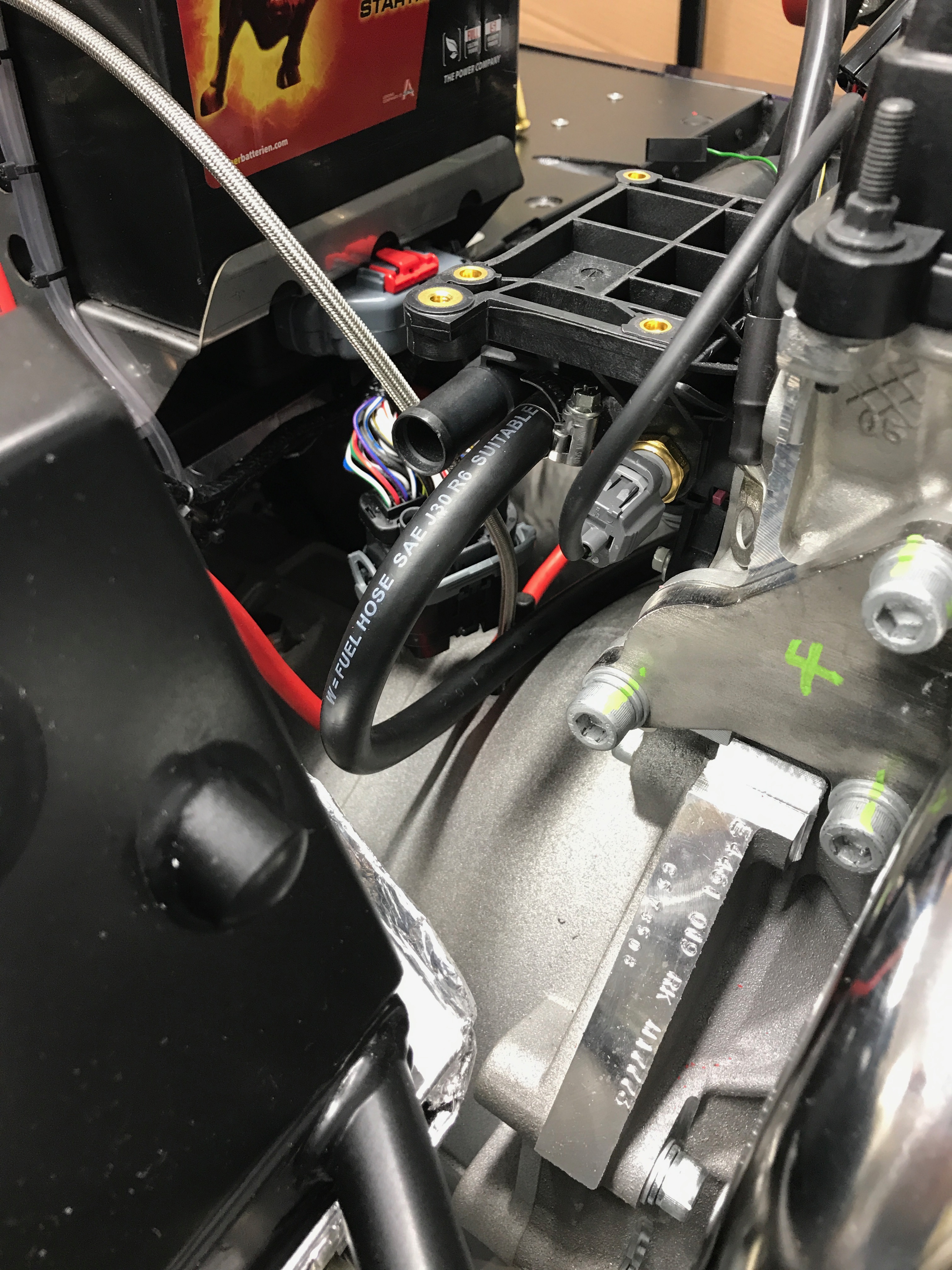
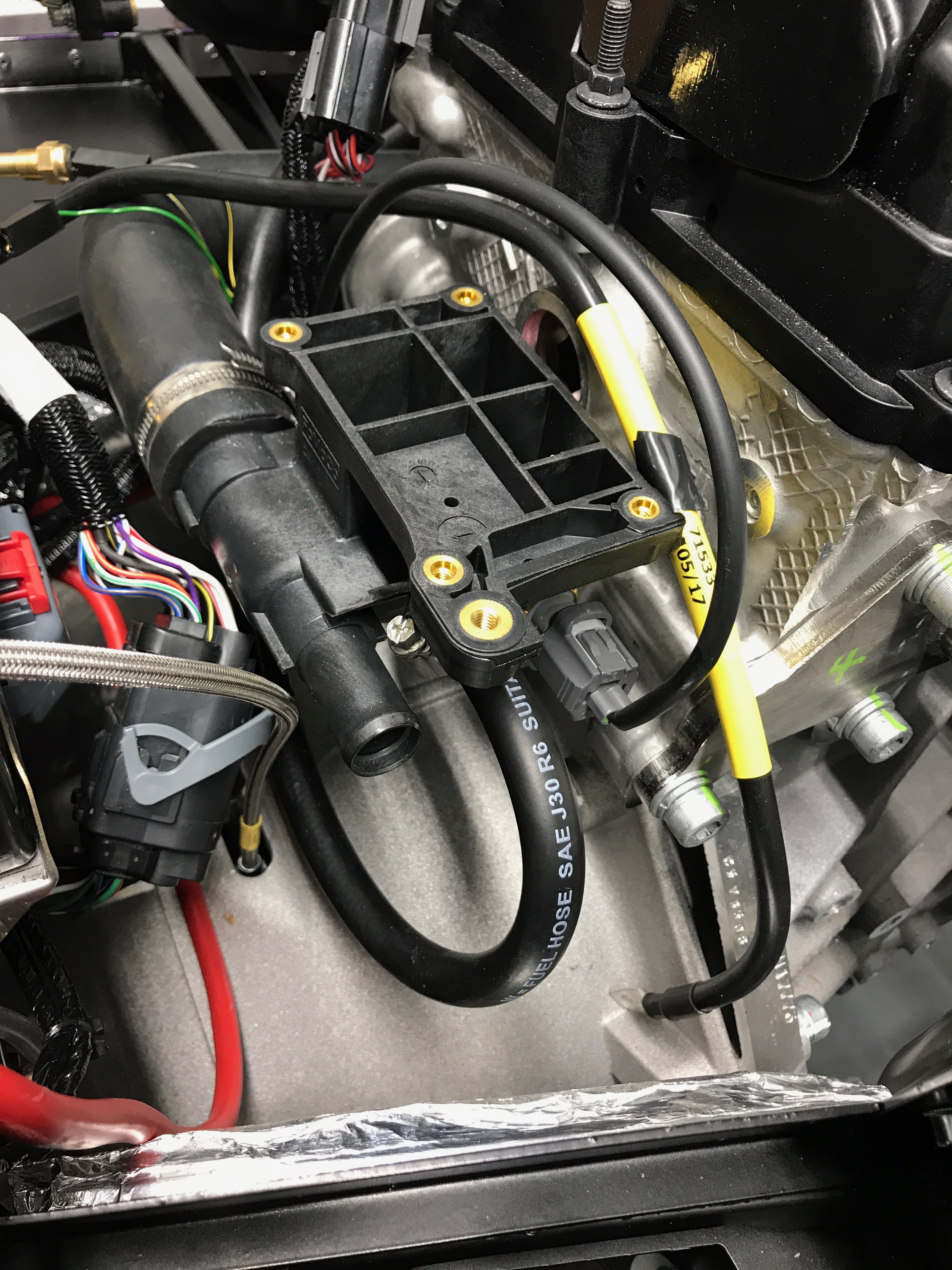
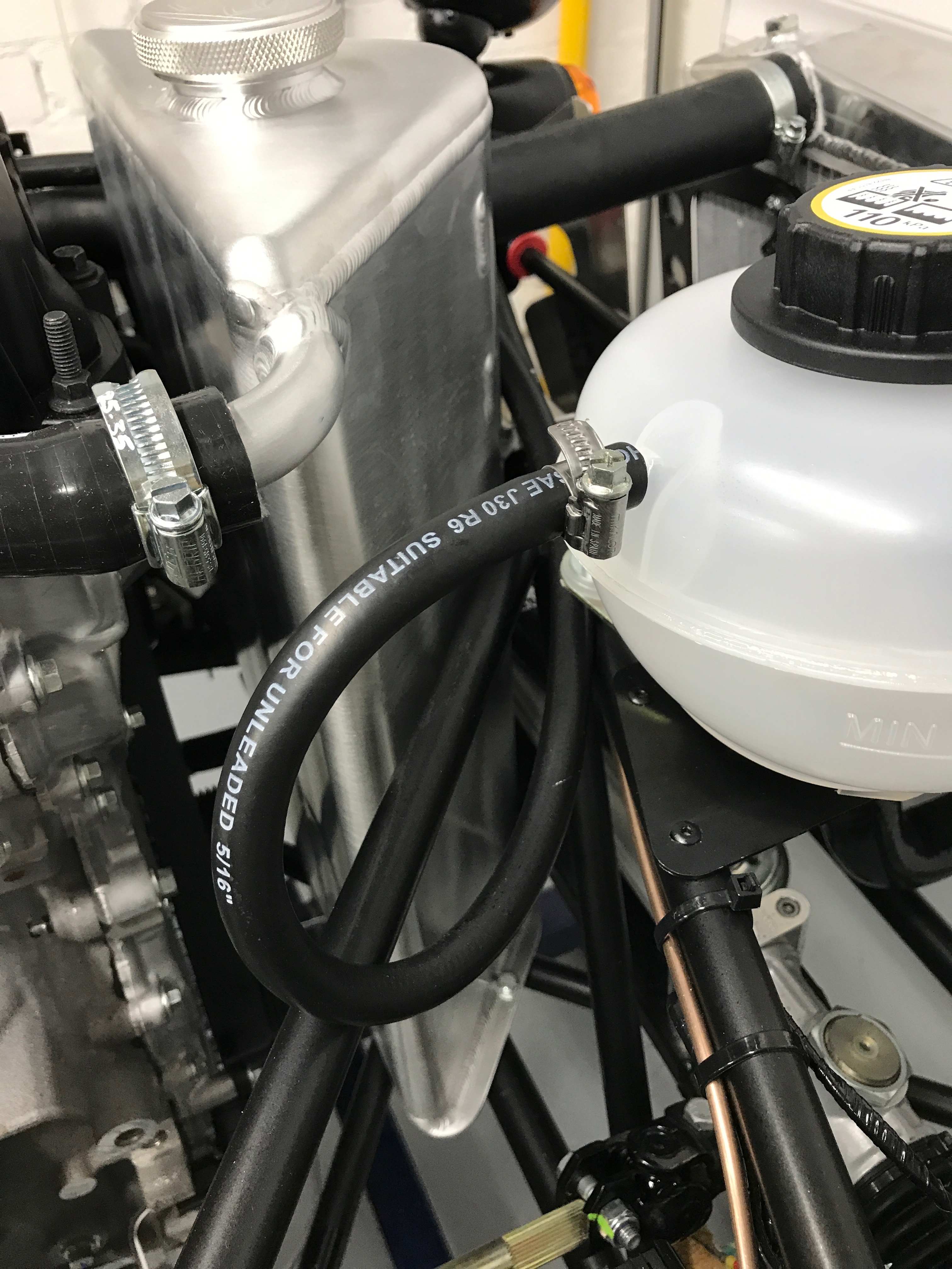
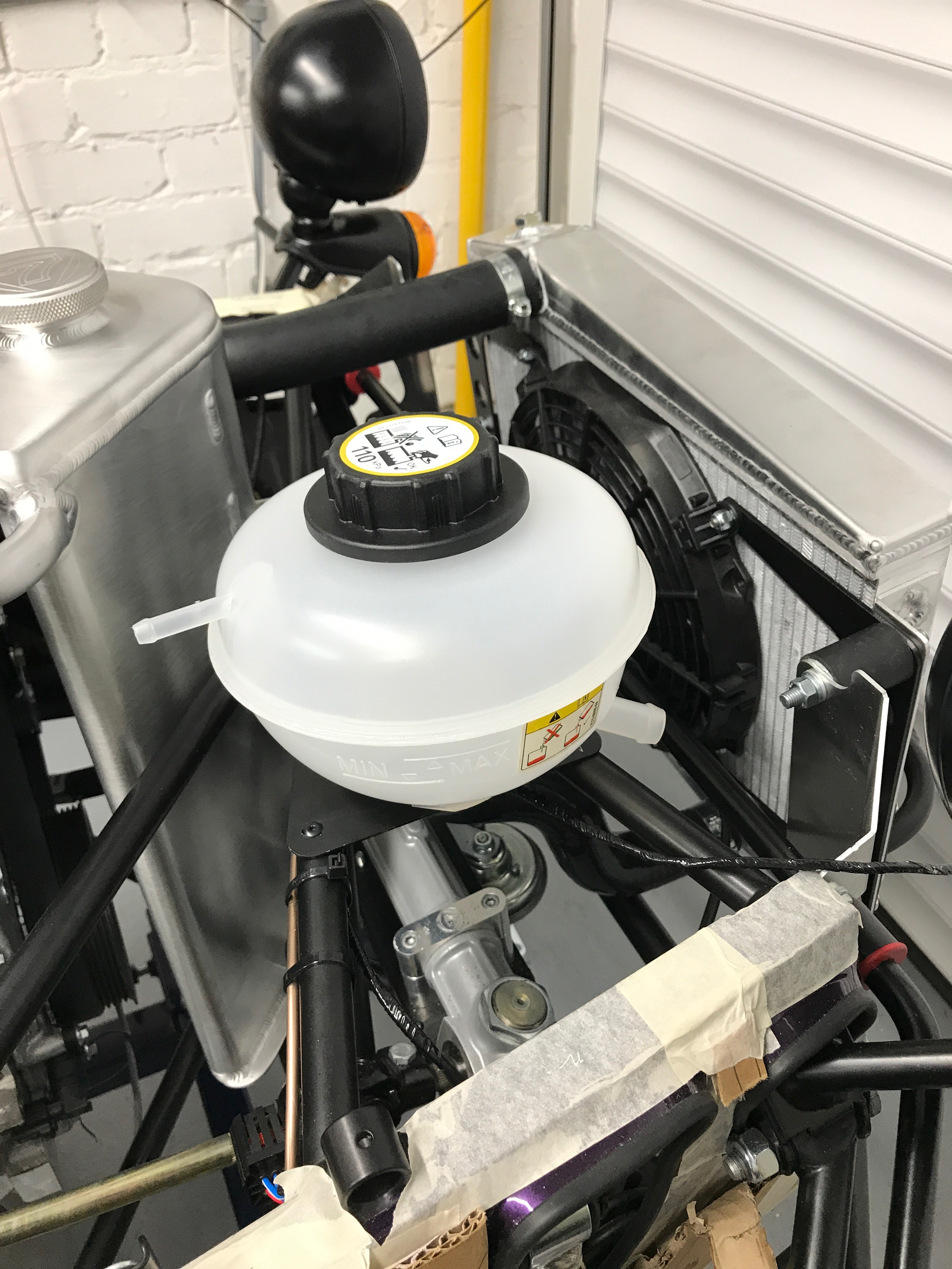
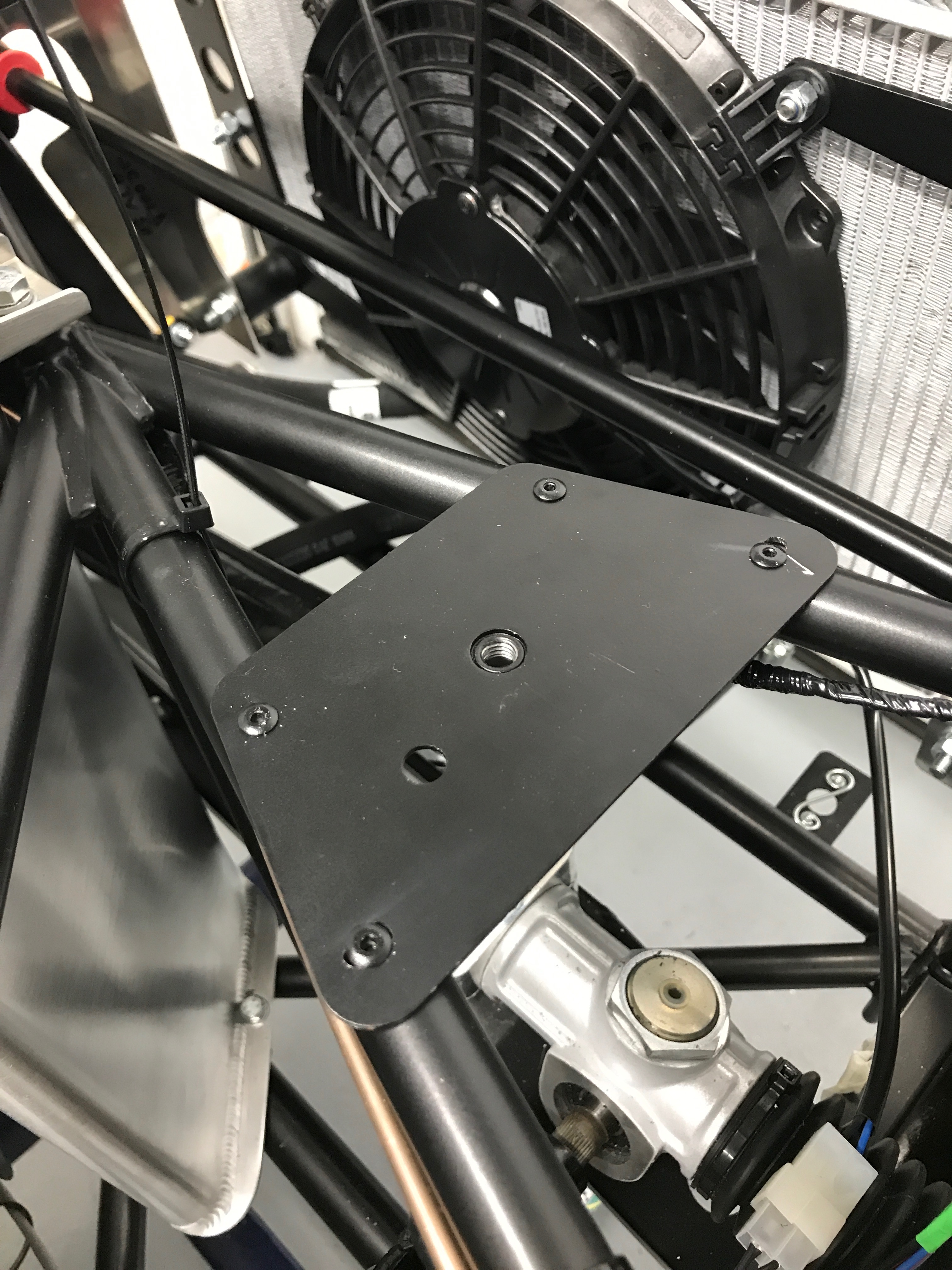
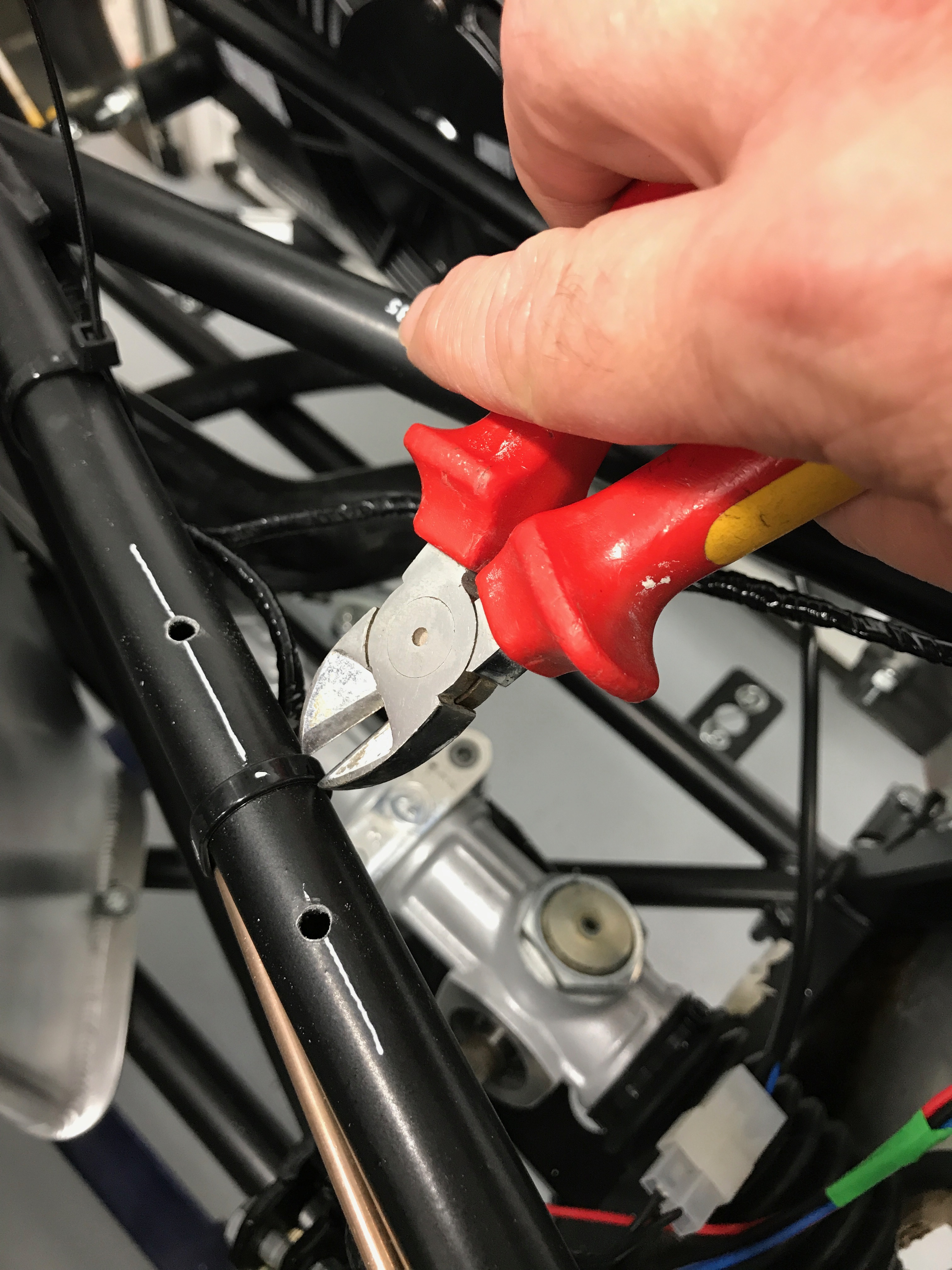
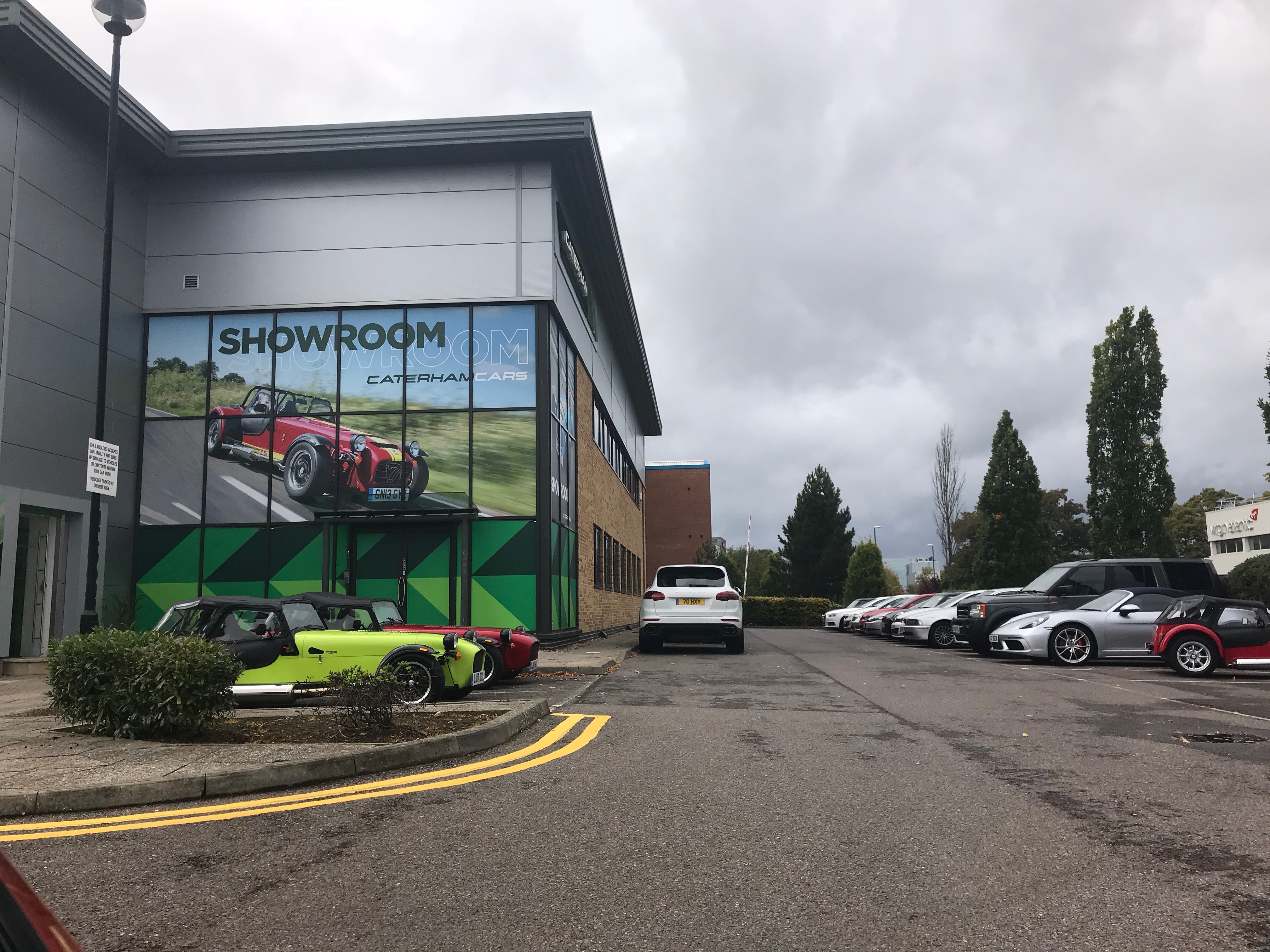
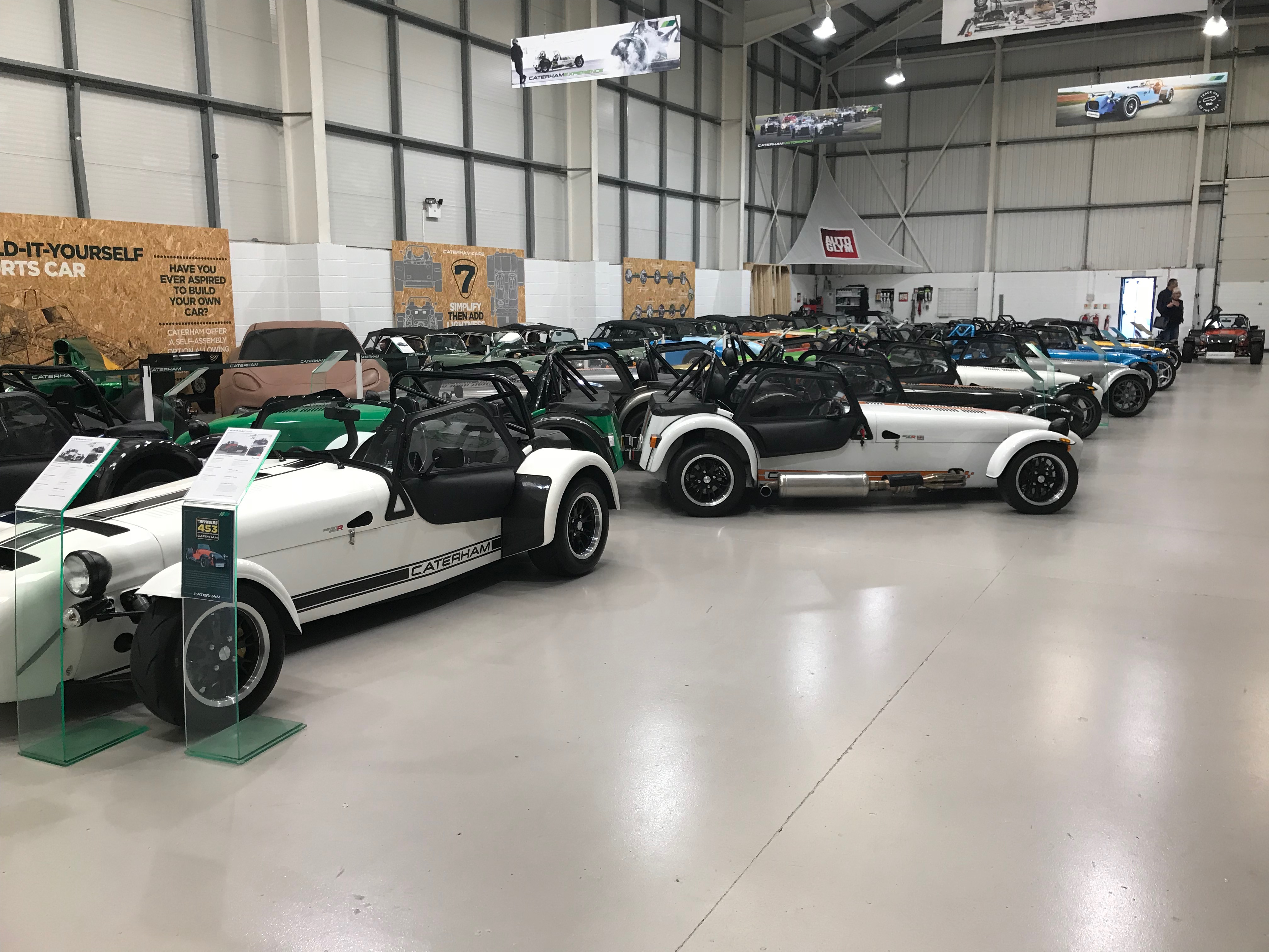
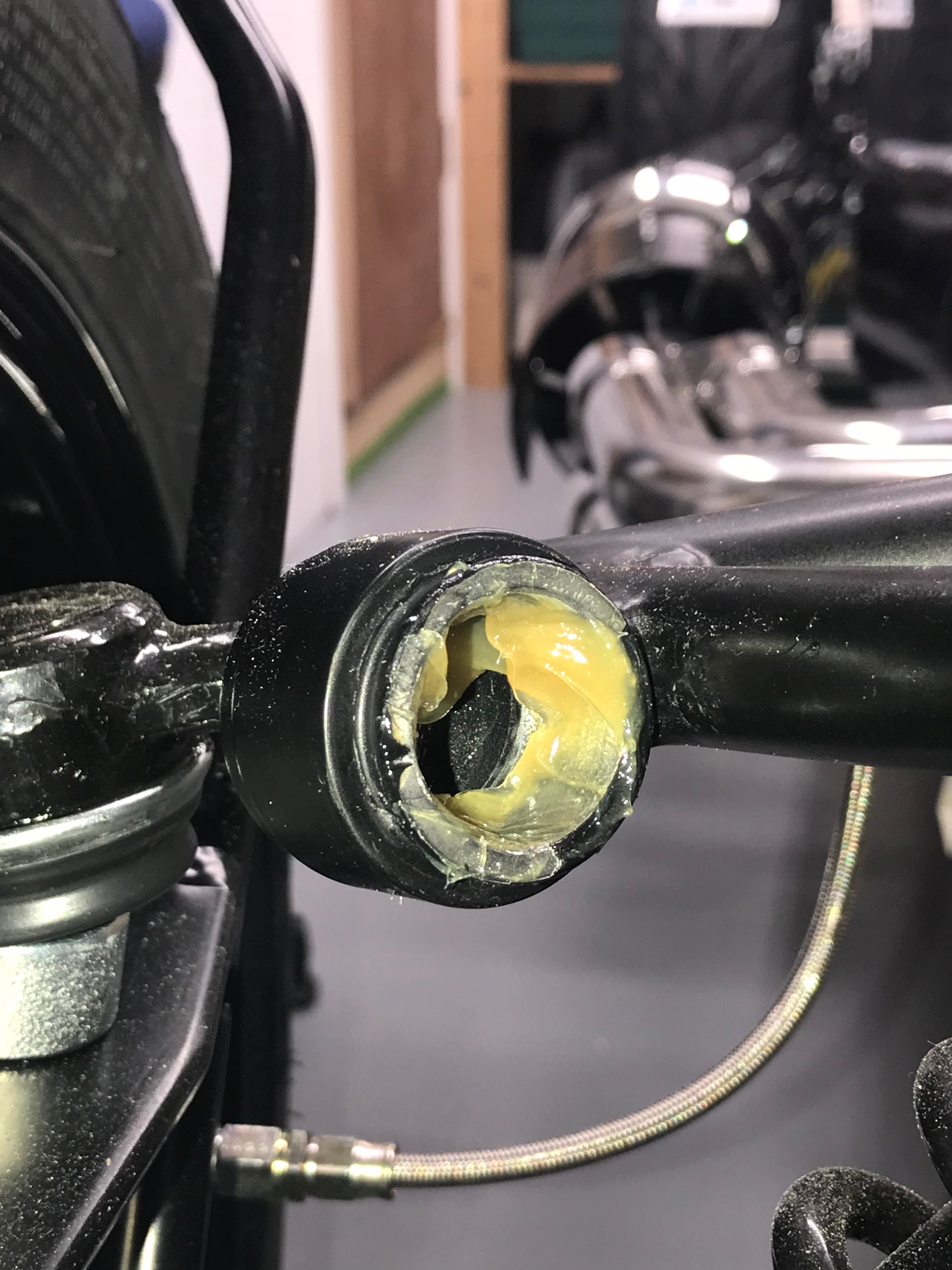
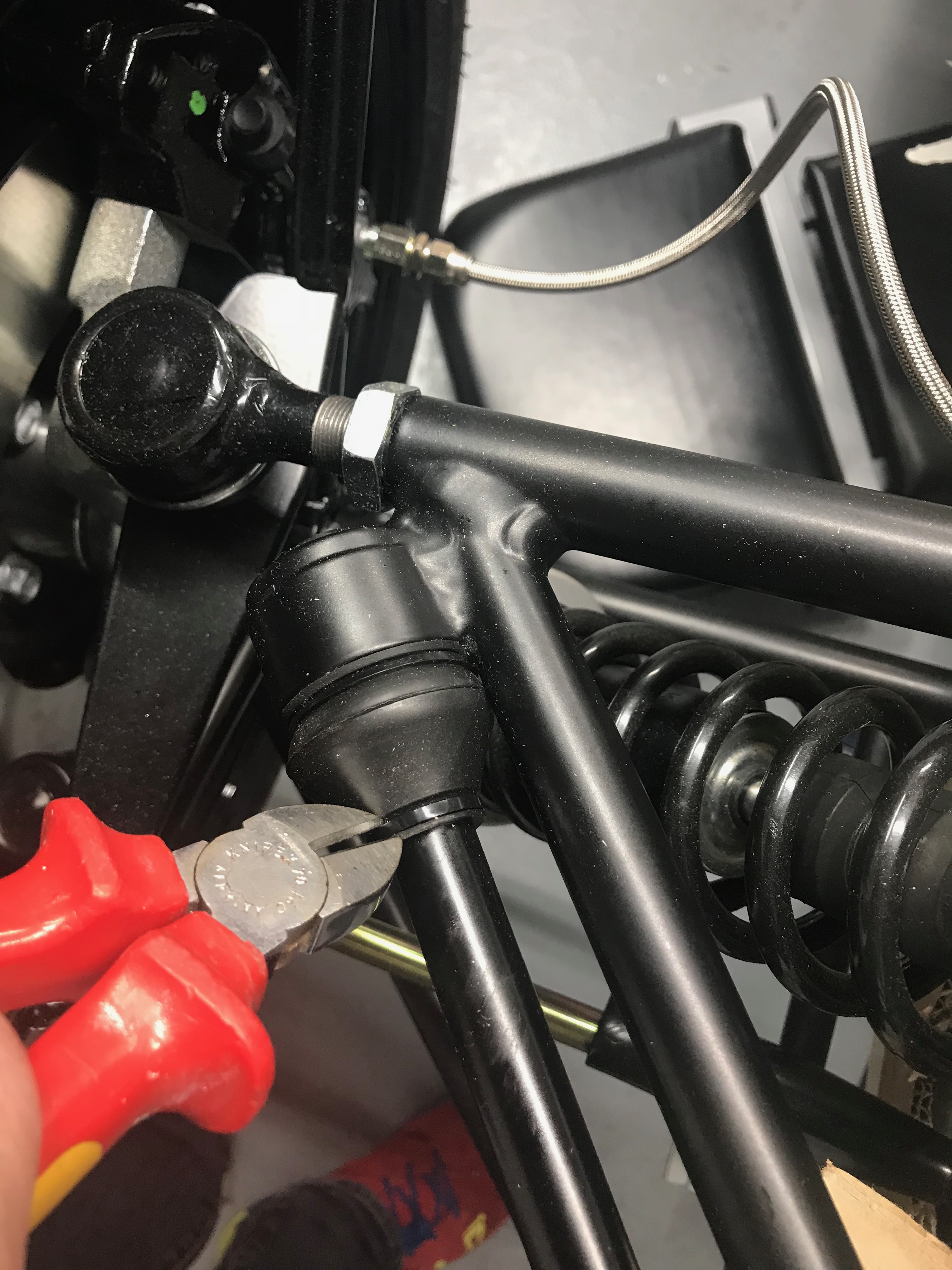
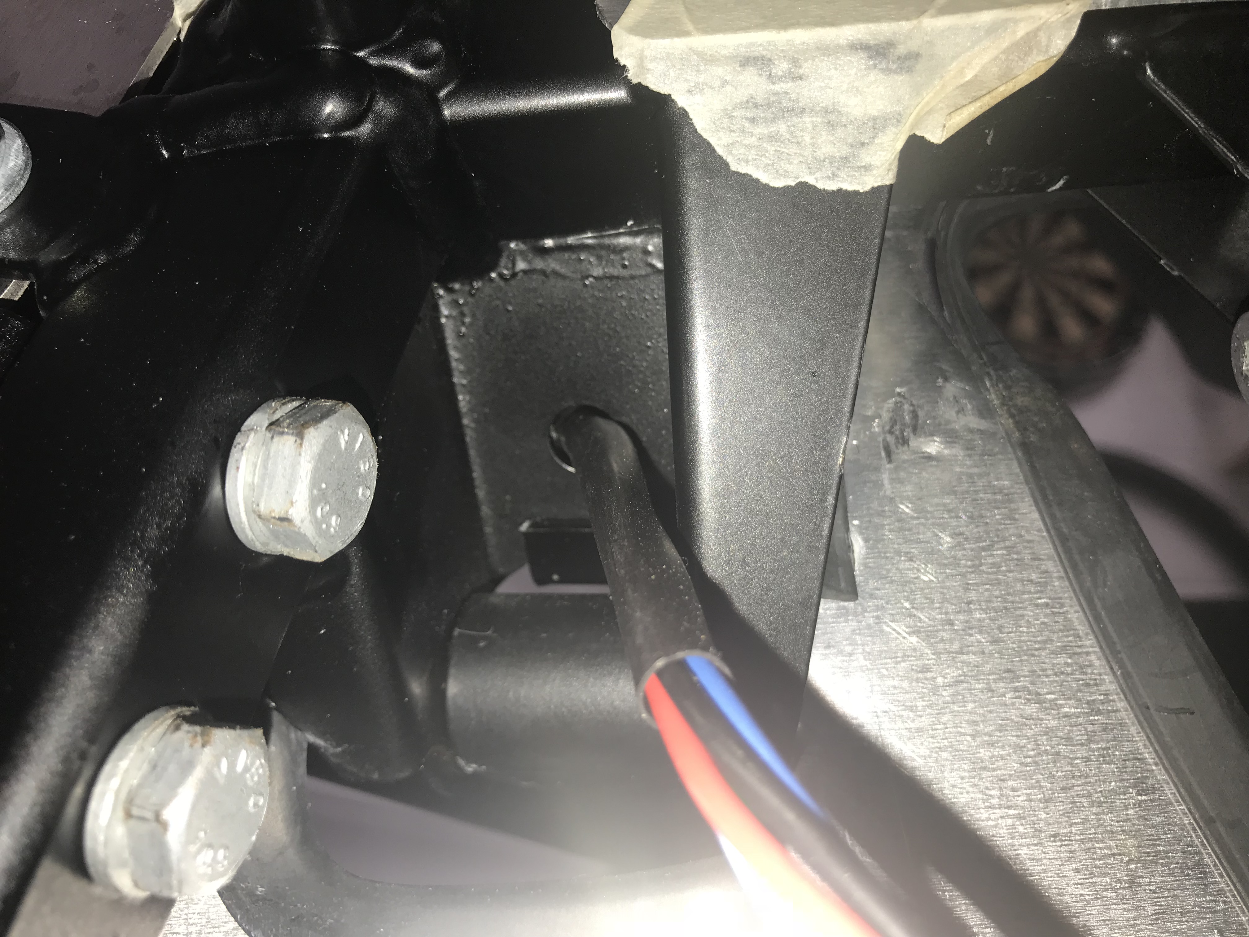
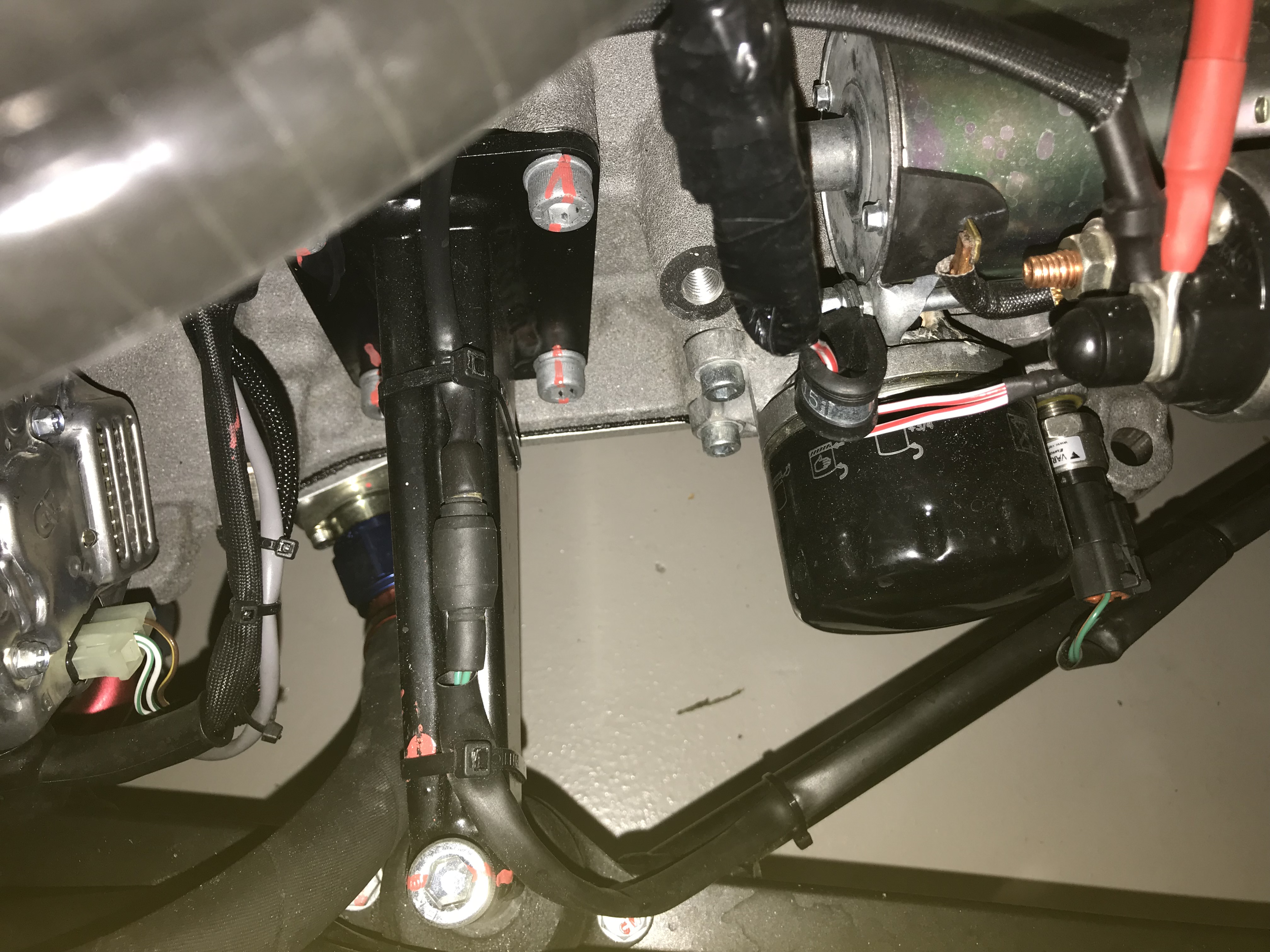
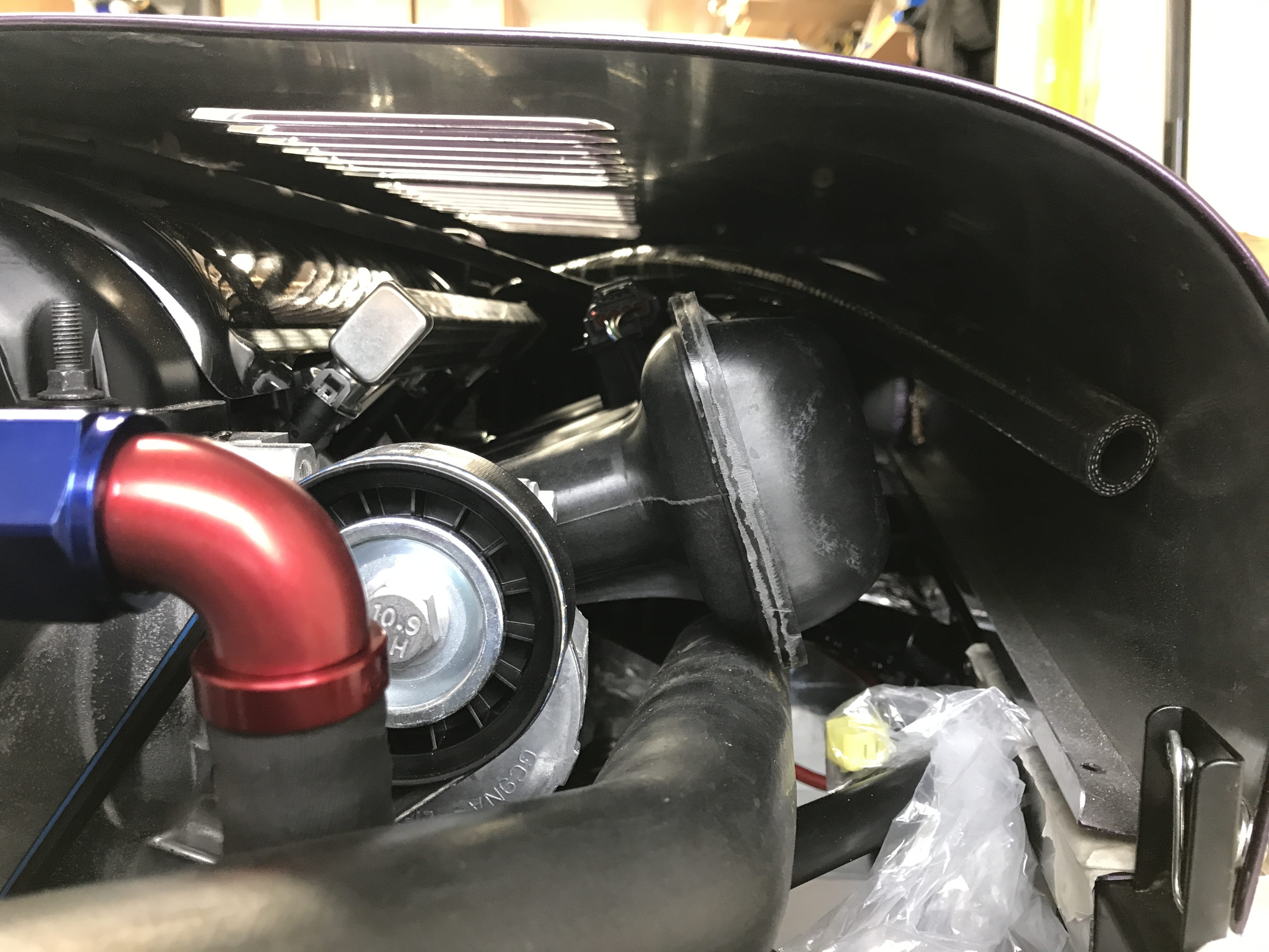
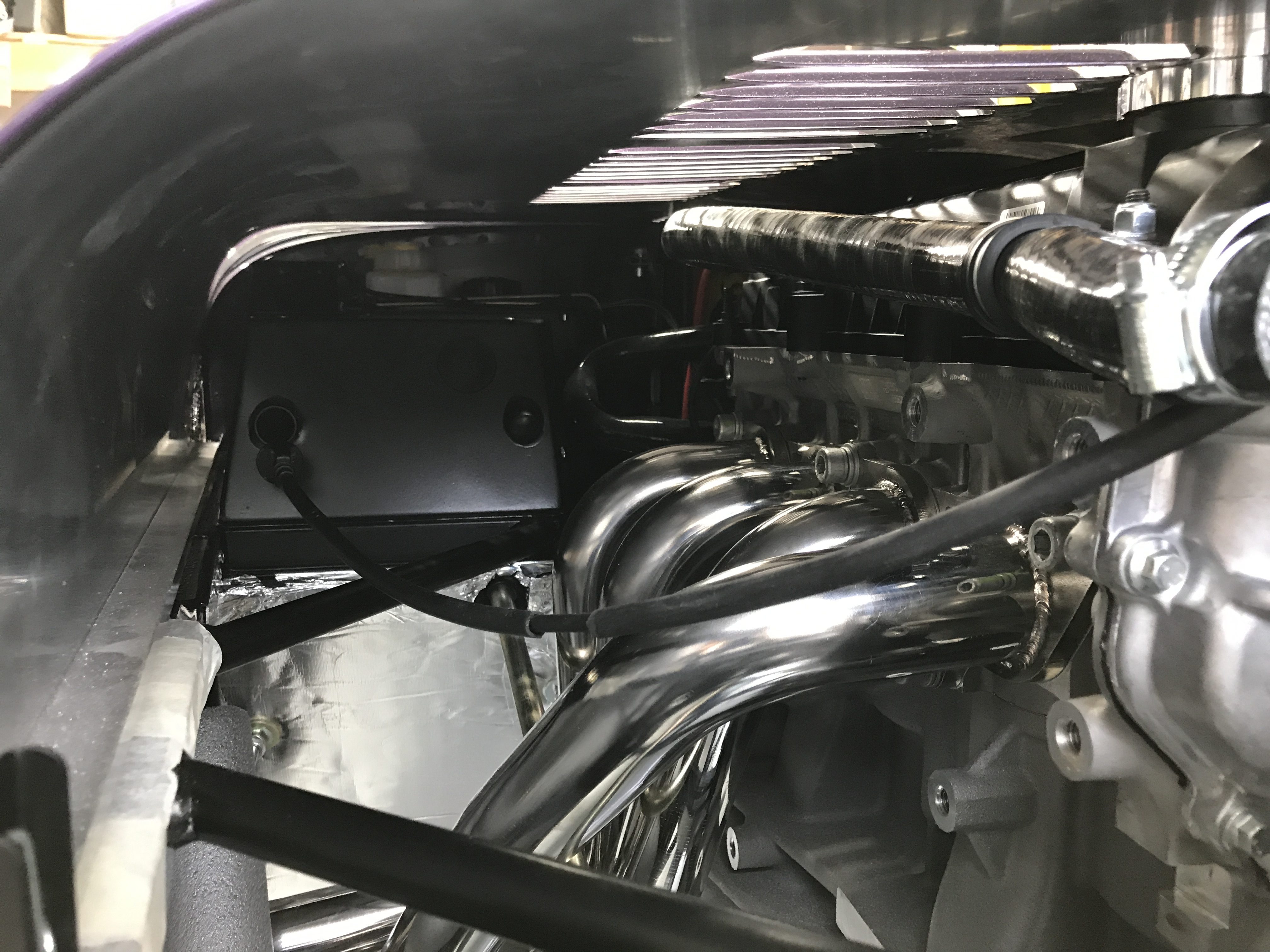
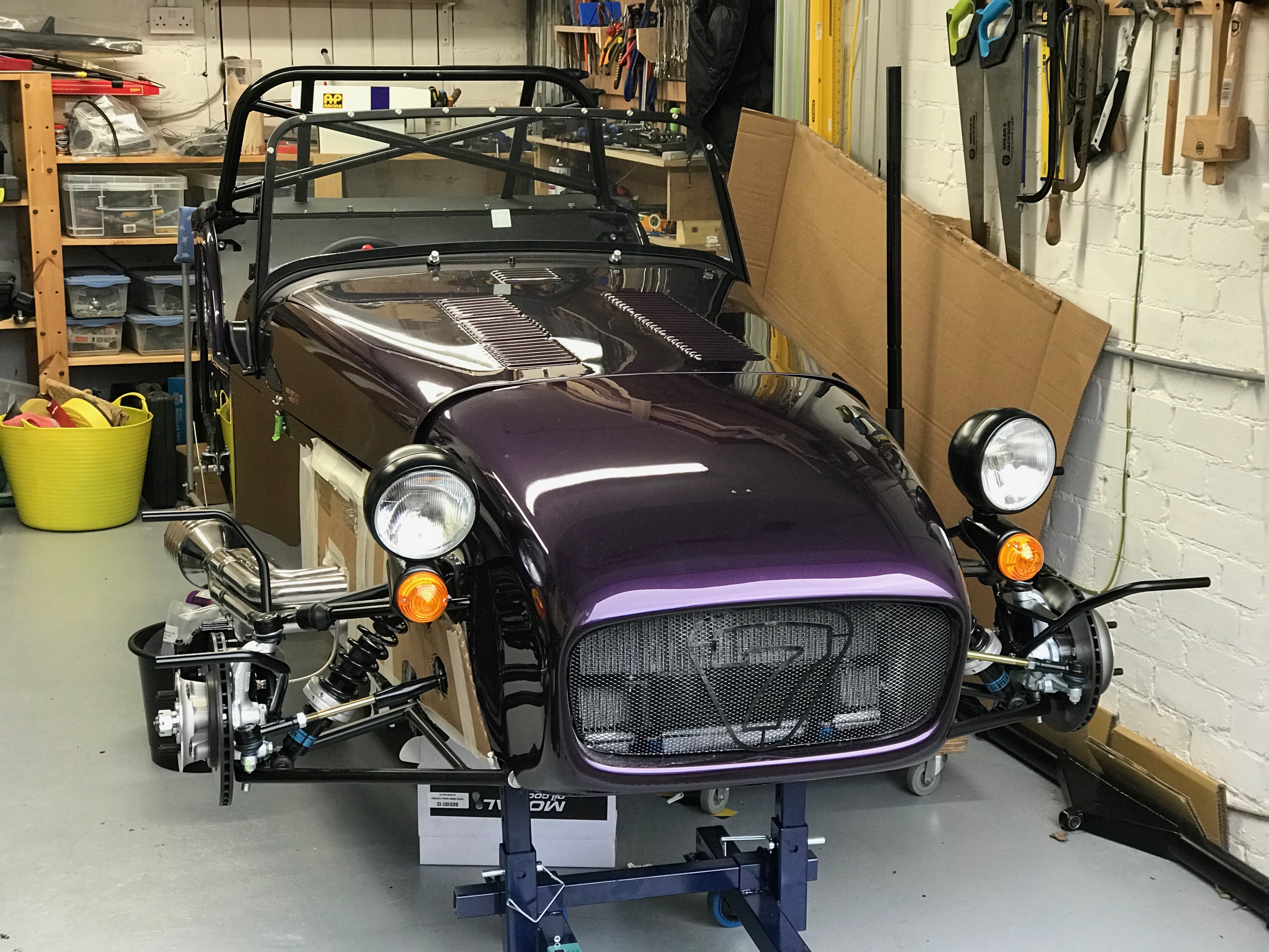
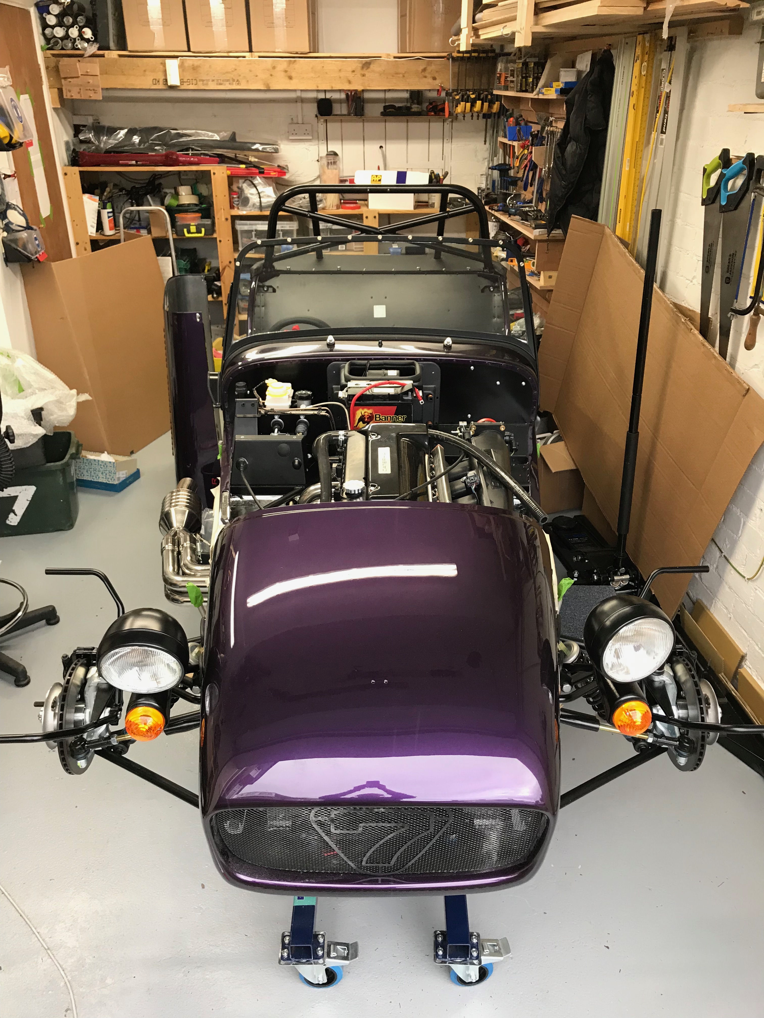
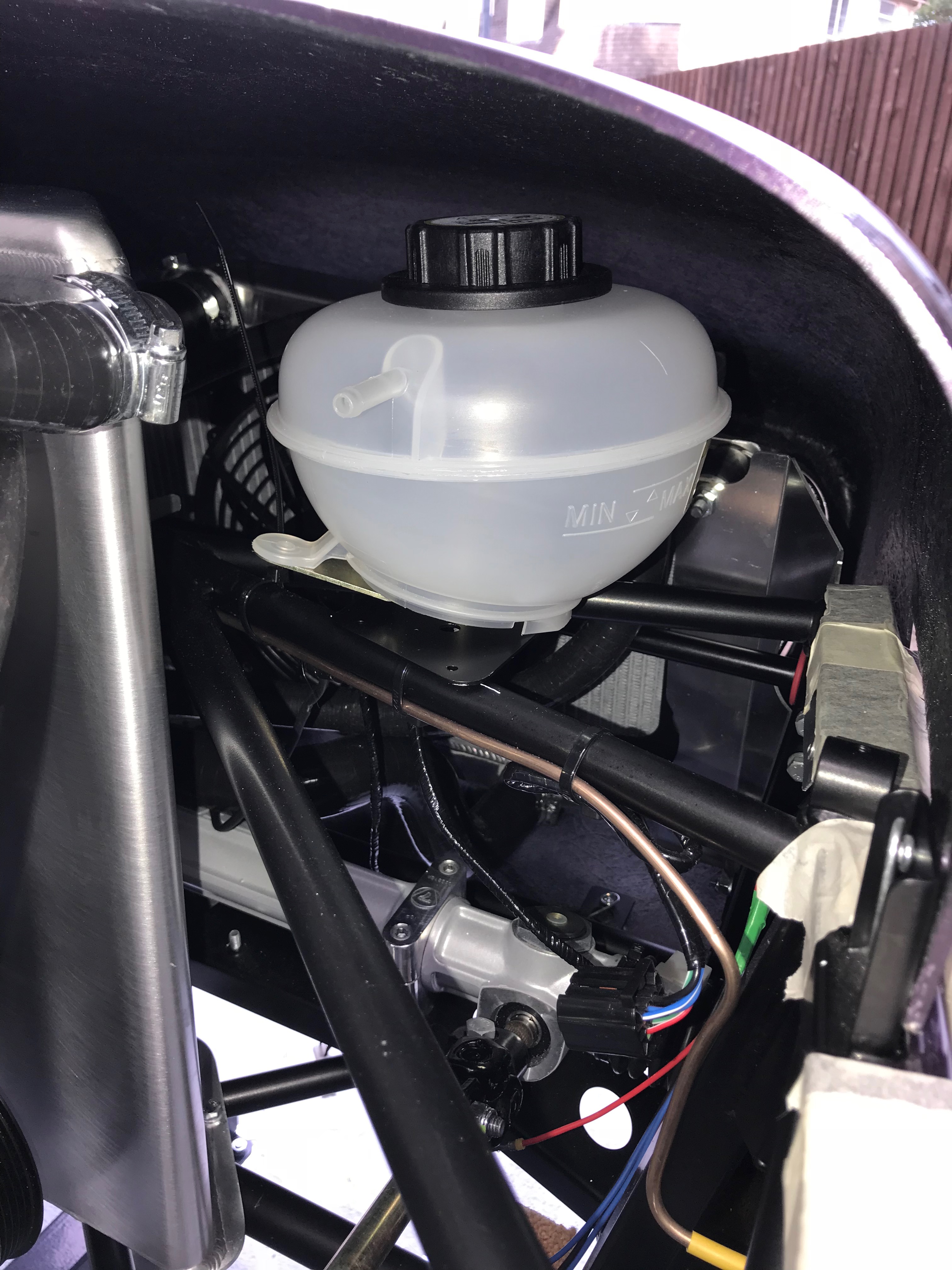
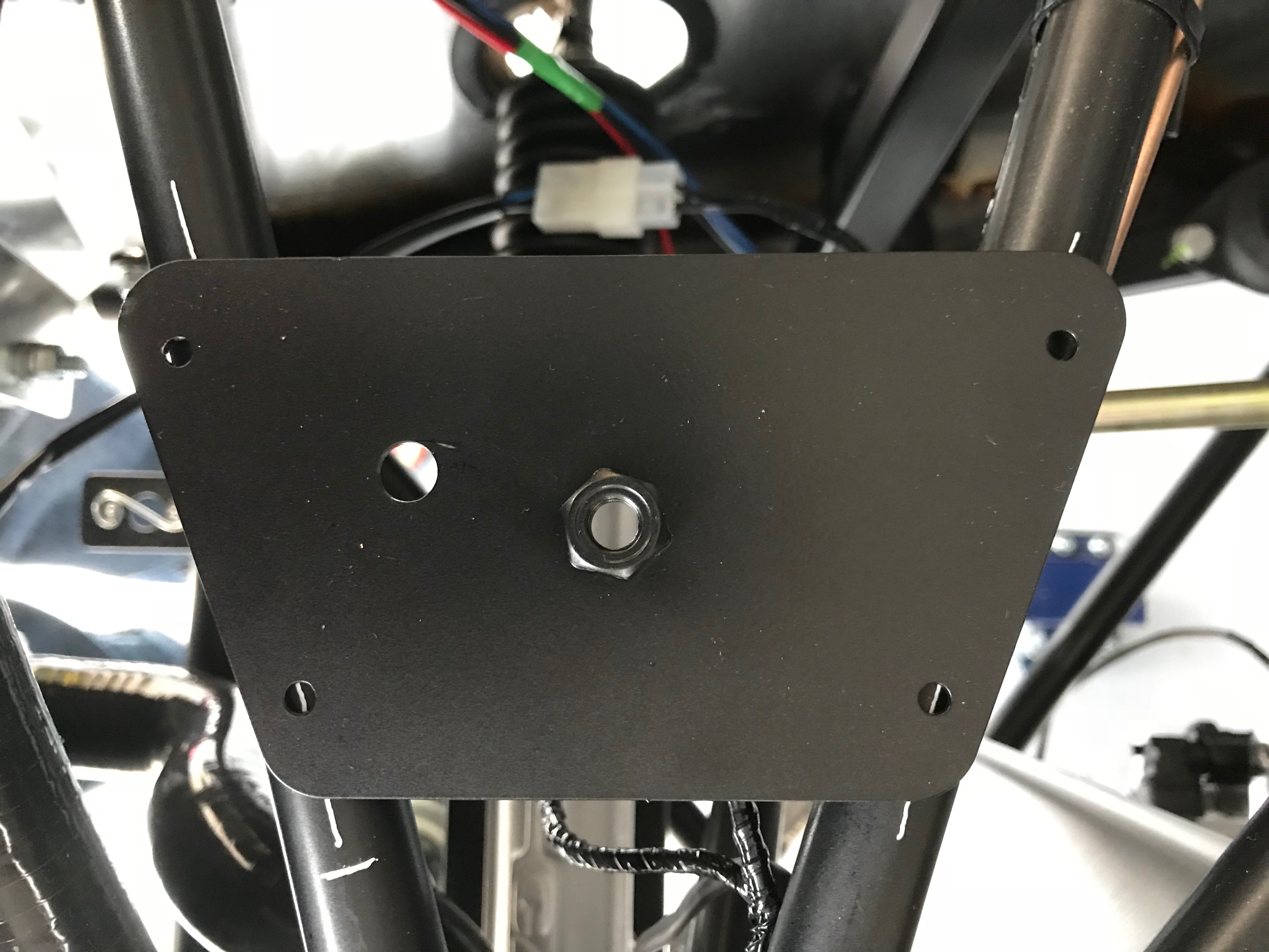
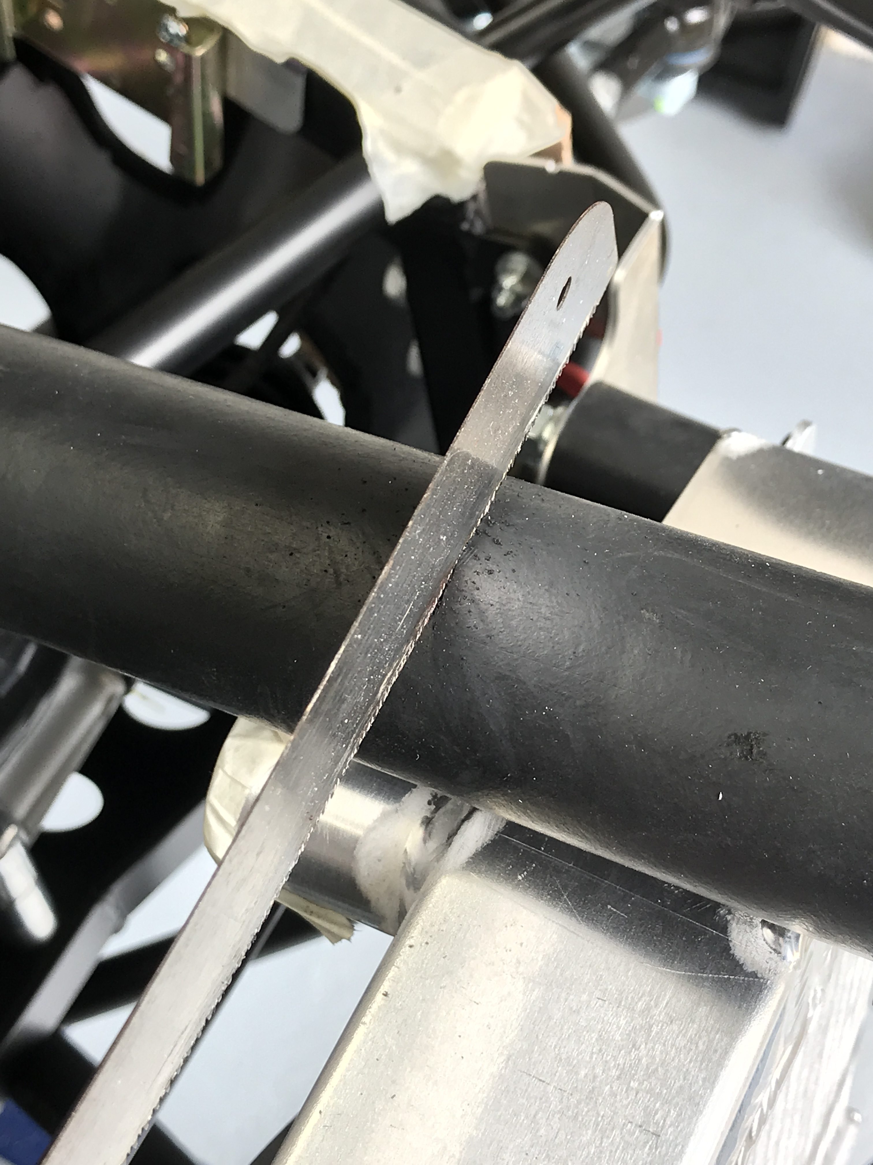
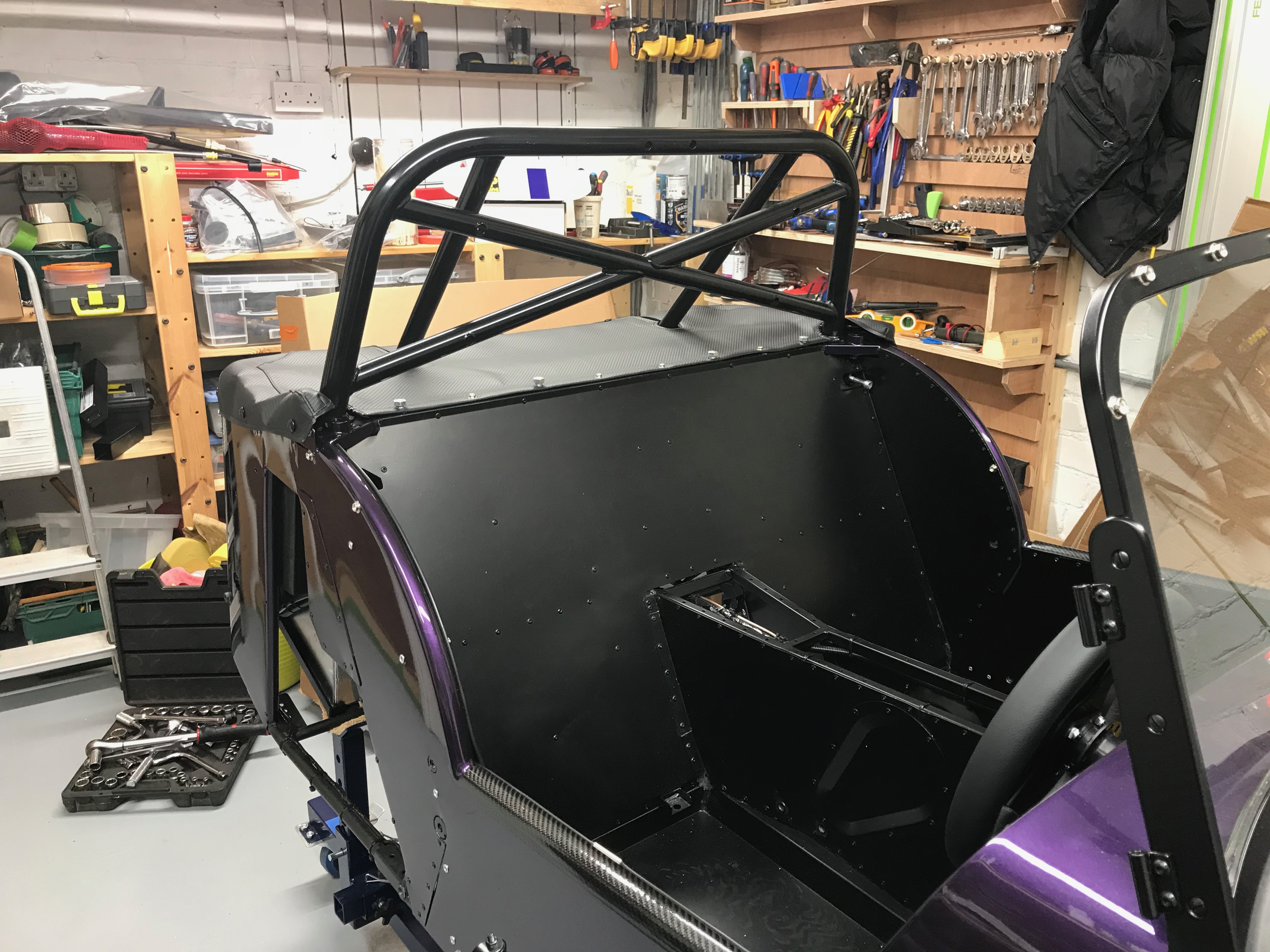
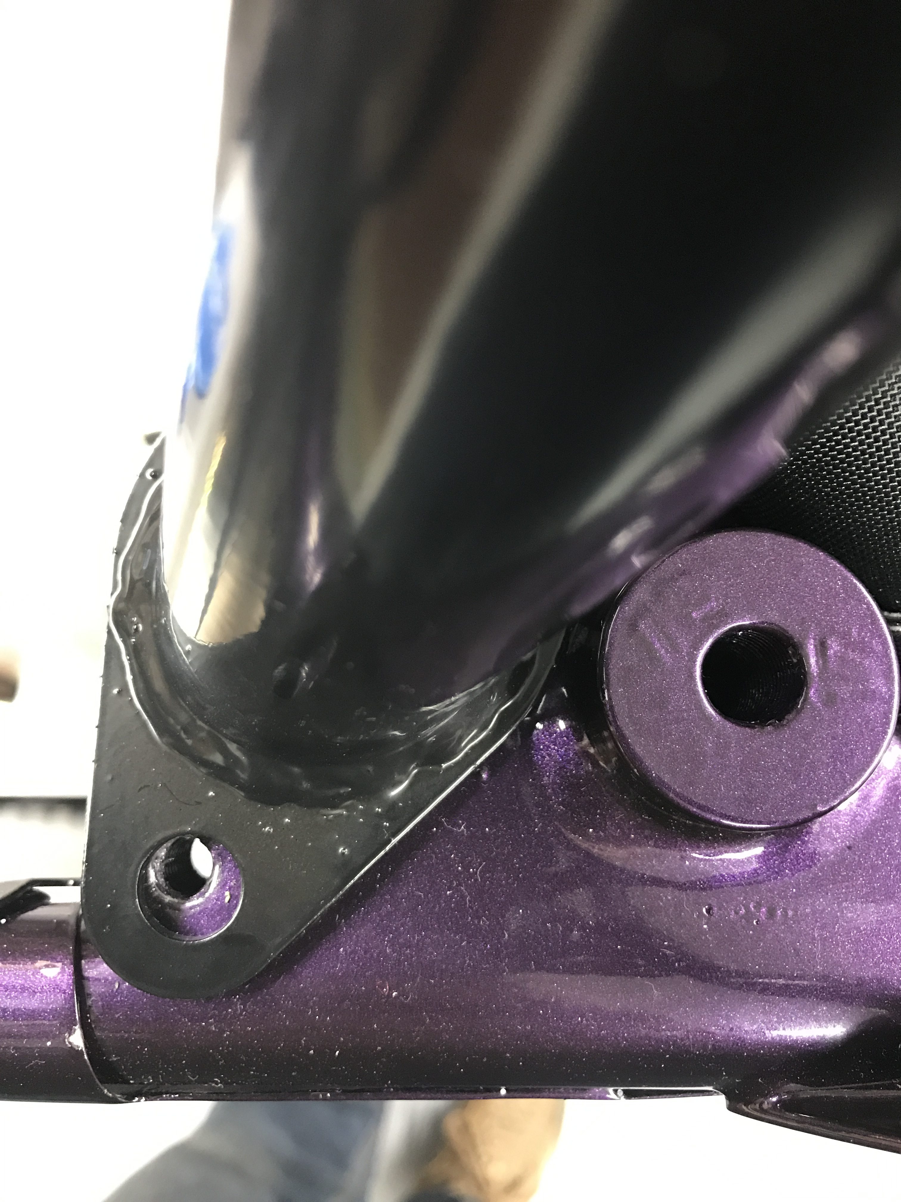
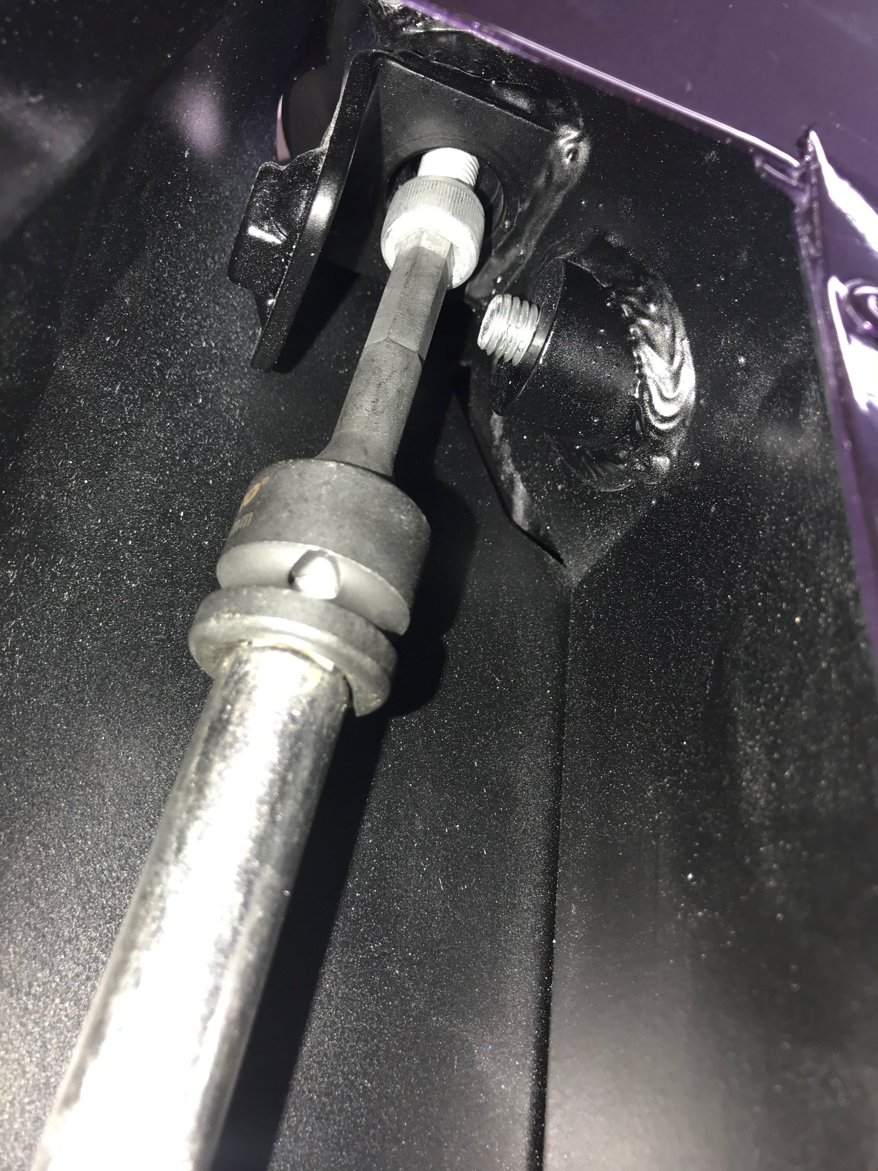
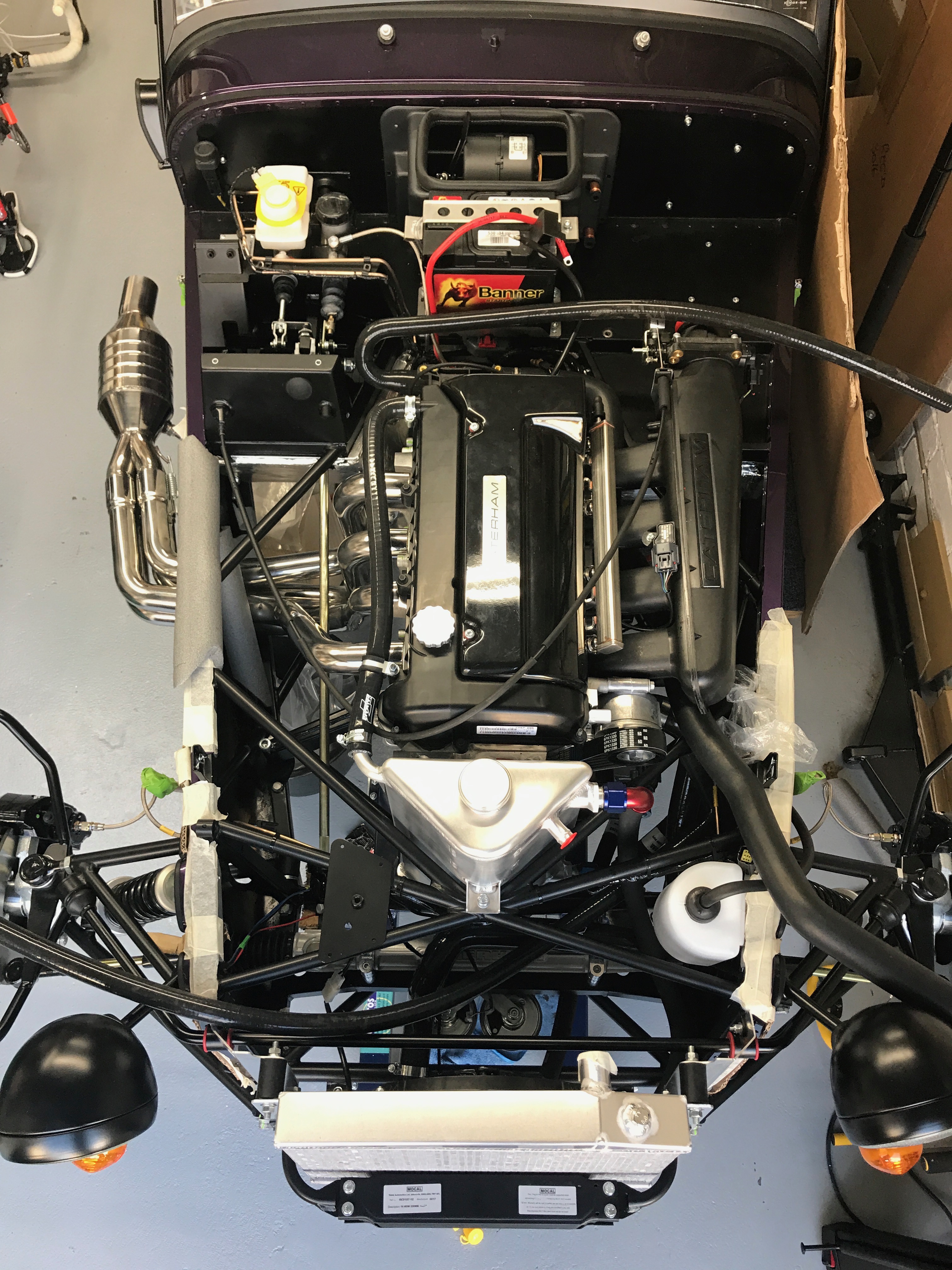
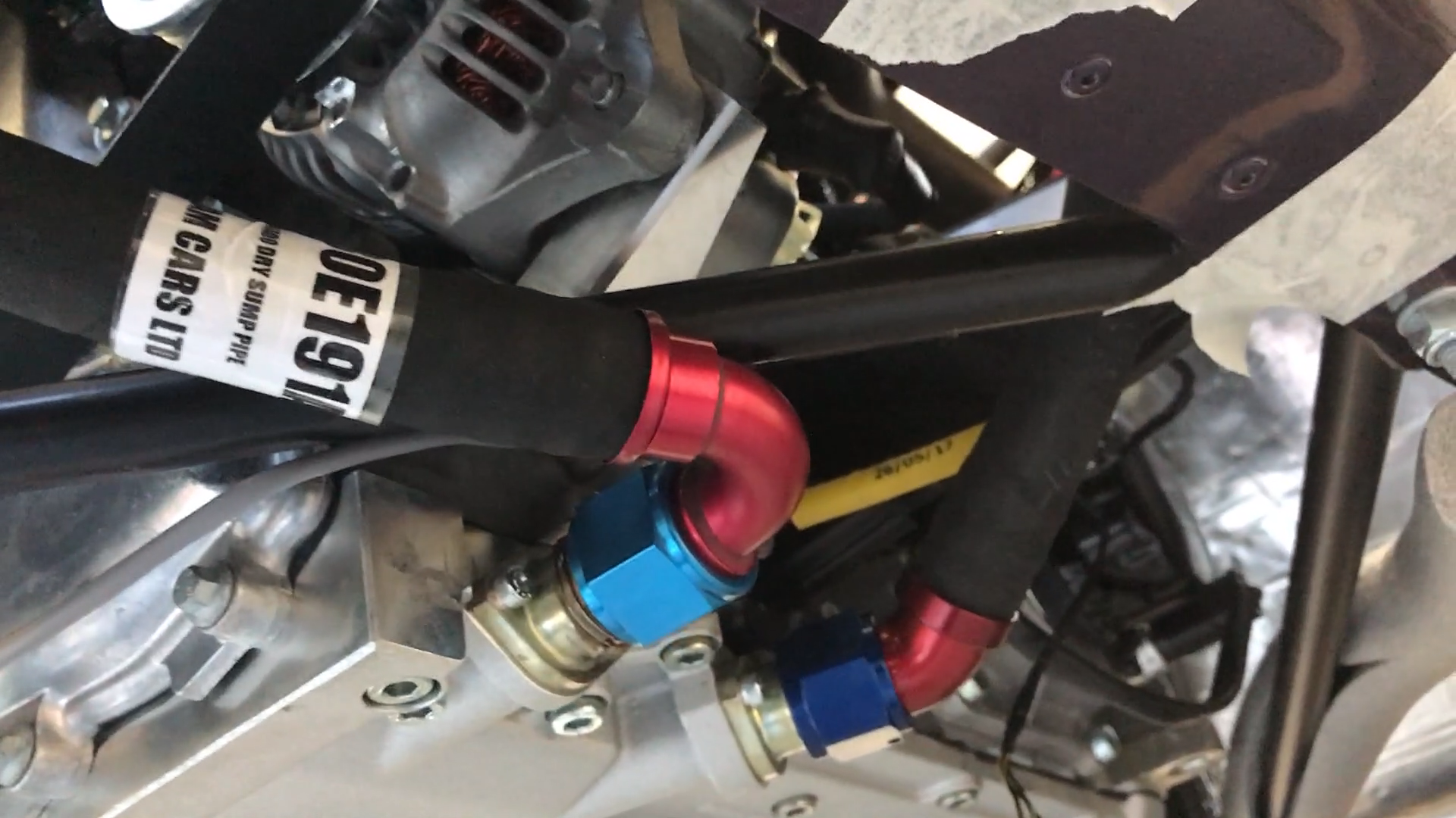
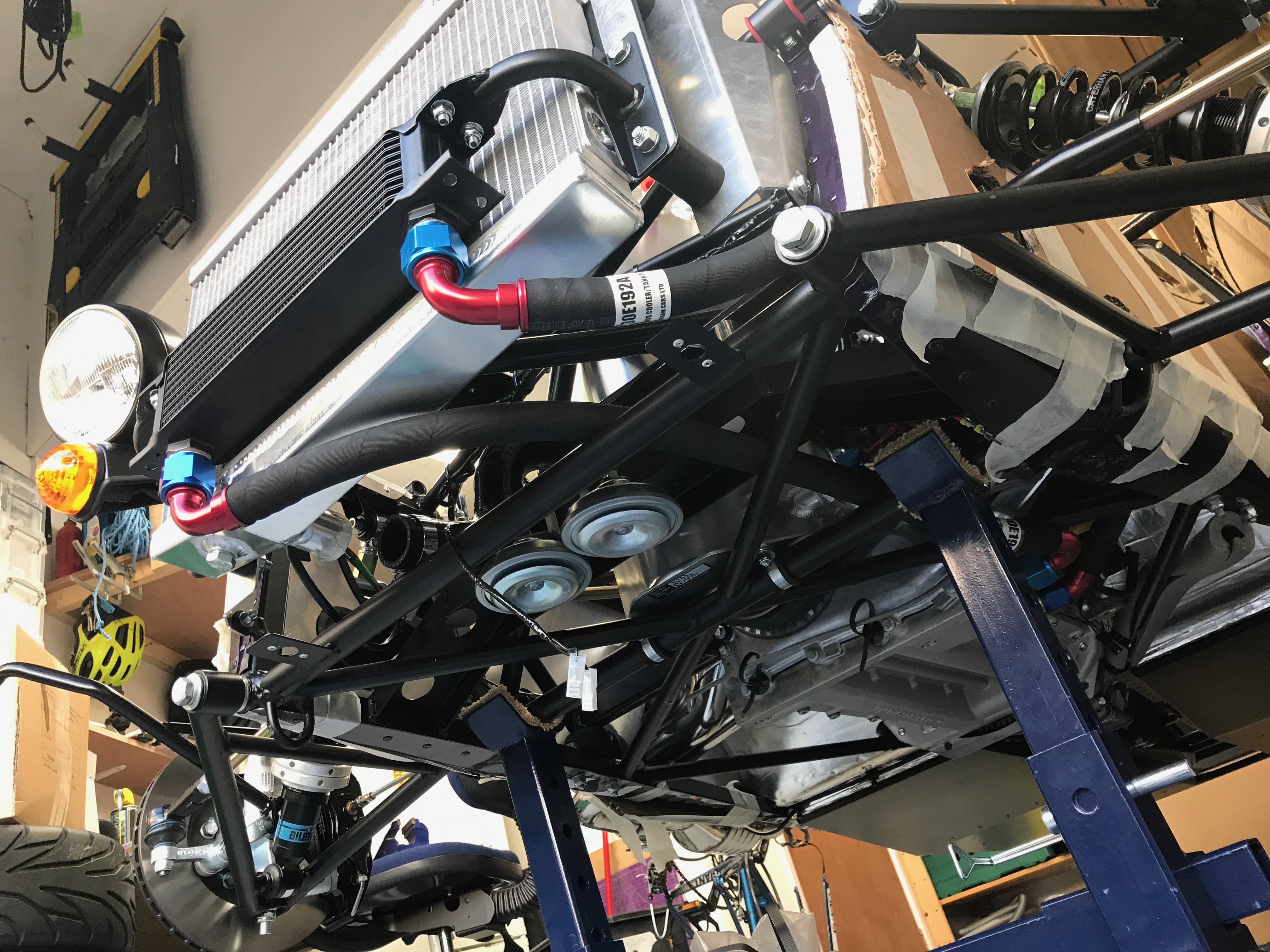
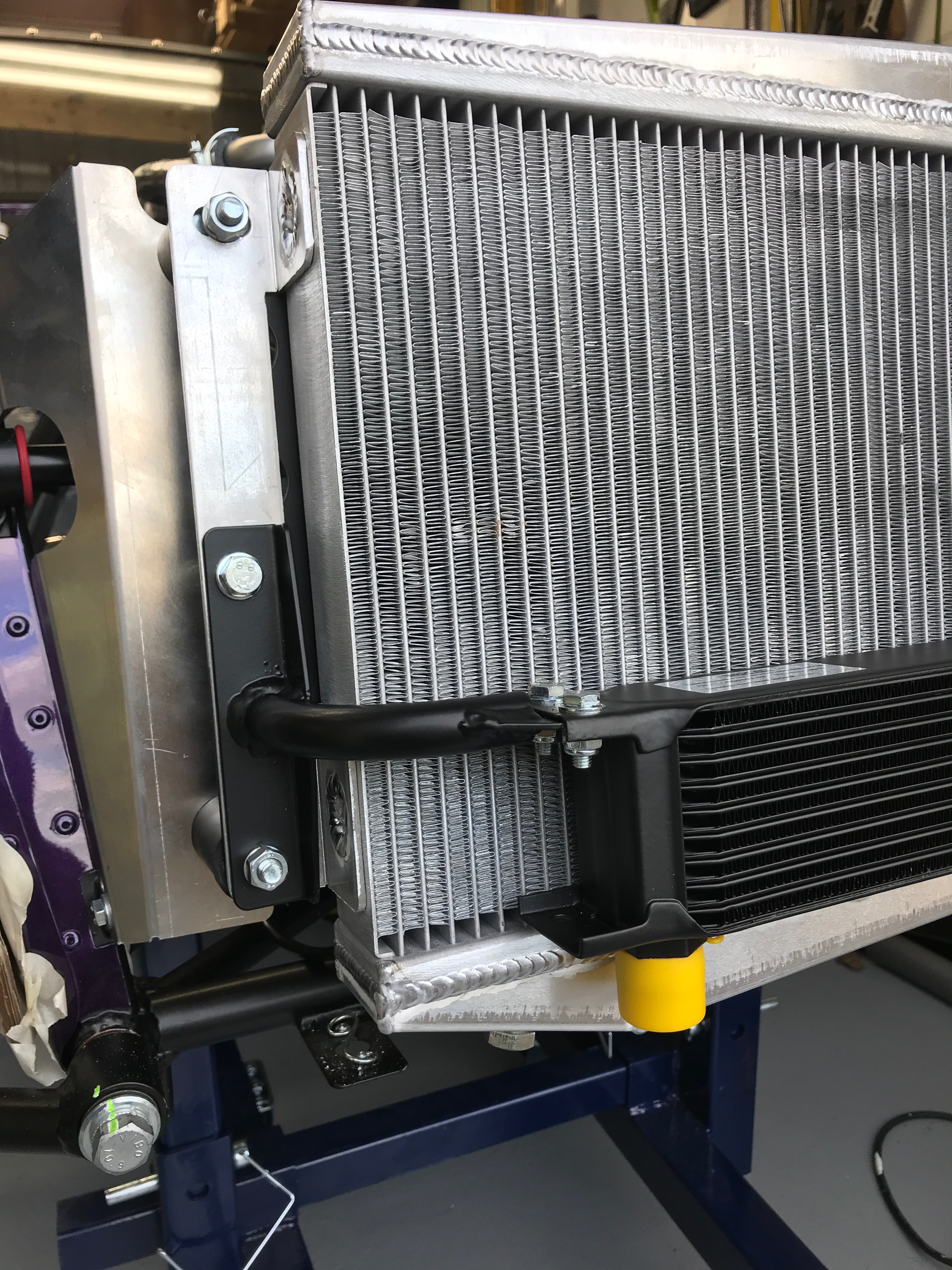
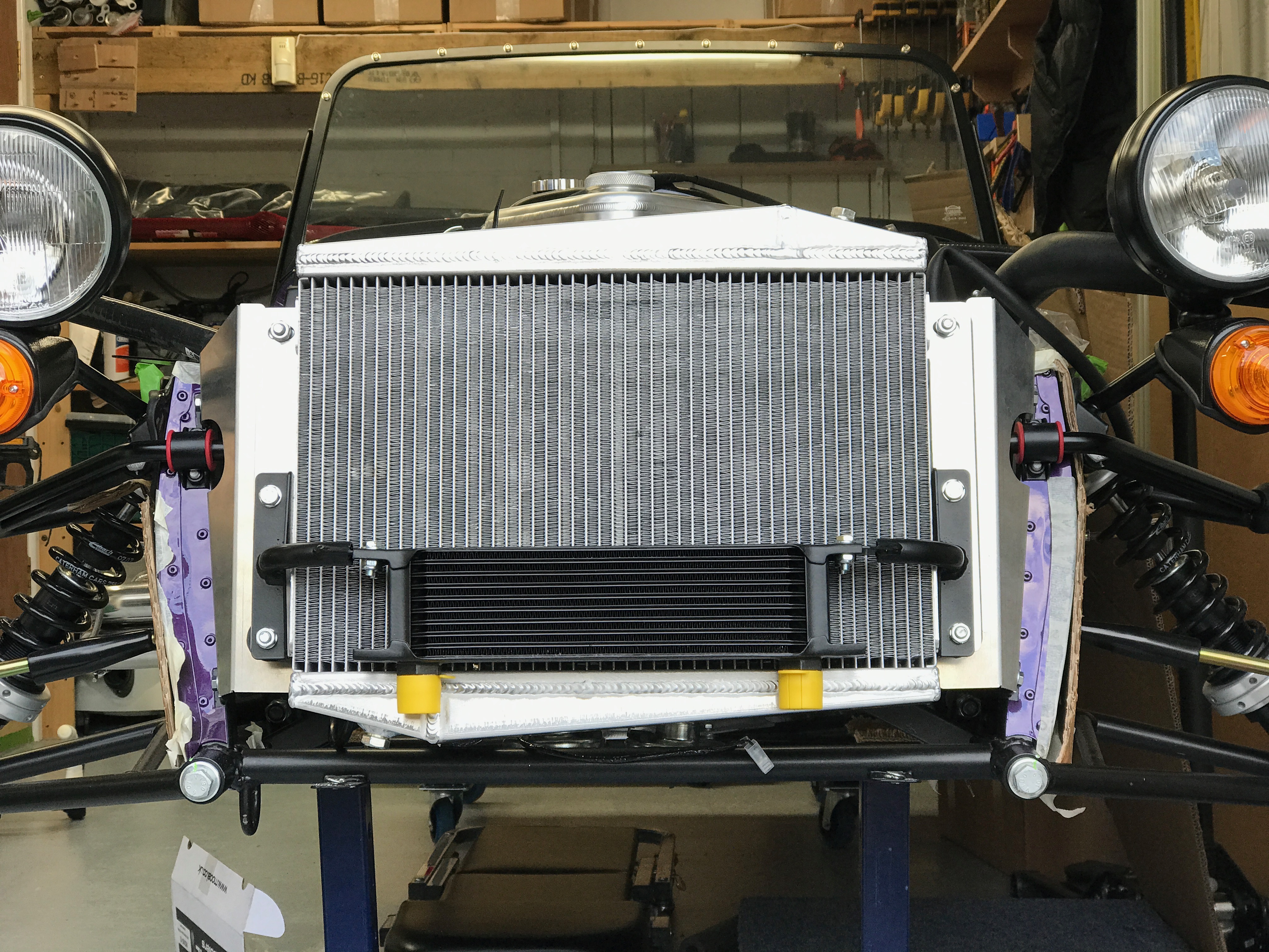
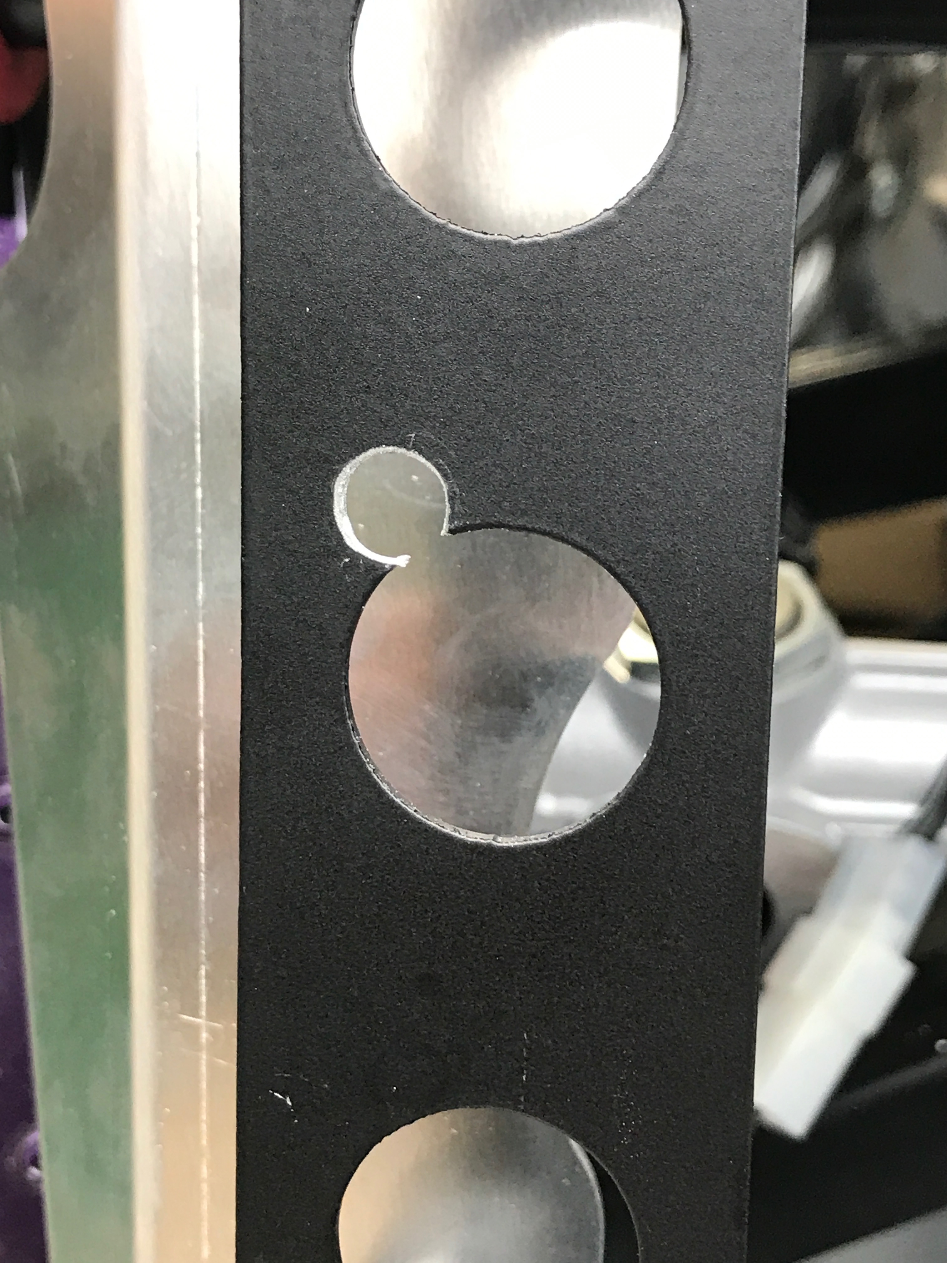
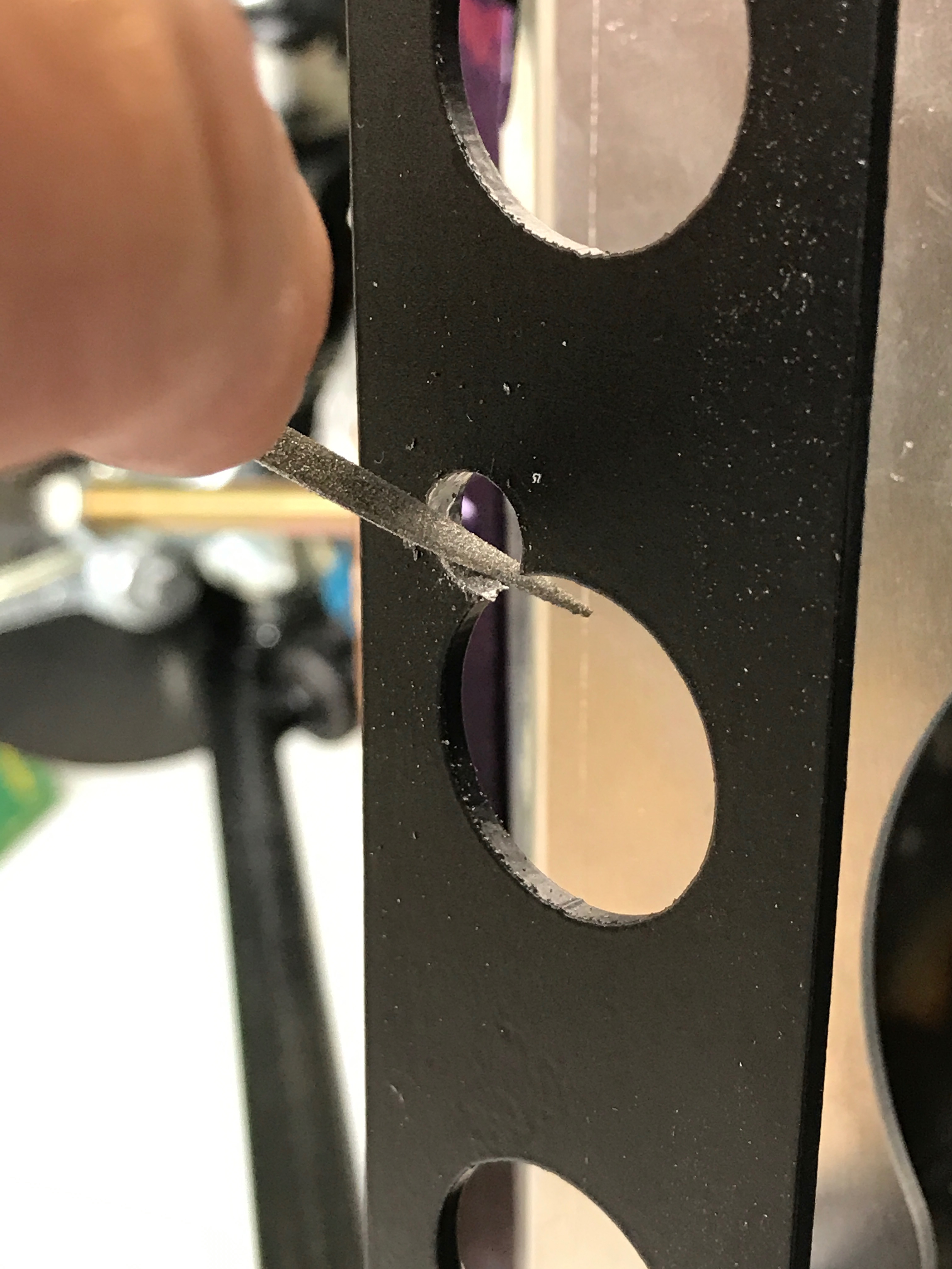
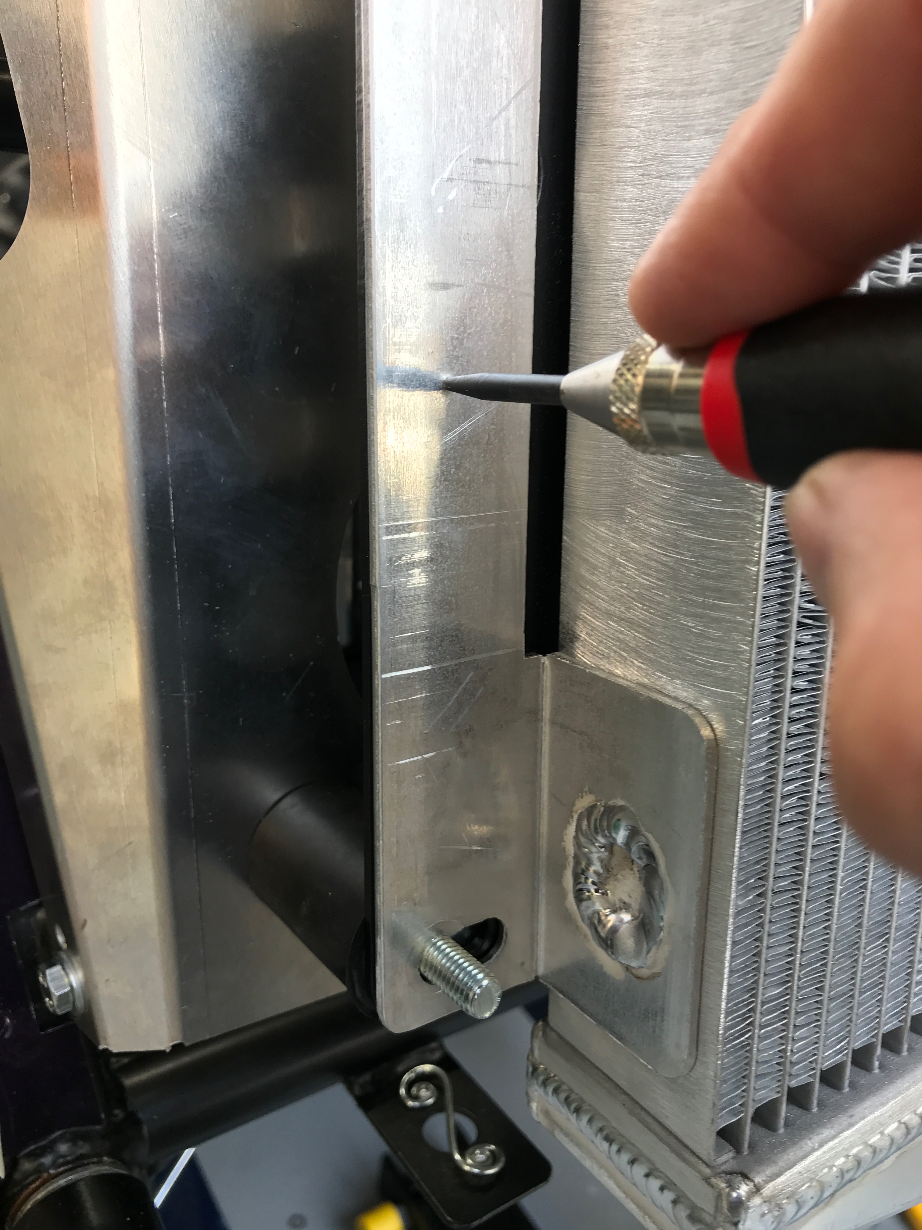
Bottom diff mountings needed 2 (LHS) and 3 (RHS) washersDigital callipers used to work out how many spacing washers are needed.Measuring diff carrier to box section the old wayLaser measuring distance from chassis box section to diff carrierBlanking/skid plate in place.Material trimmed from skid plate.Sand off some material from the skid plateThat’s not right… there’s a hole that all sorts of stuff is going to get intoWhat was this?Big screwdriver (top right) used to secure diff in top mountings. This will be the last useful job this screwdriver performs… read on for its finale!Trolley extension piece :-). Gets used lots in the future.The two top and two bottom mounting pointsDiff ready to go in and trolley jack poisedProp shaft finally fed into the gearbox. You can see one of the U shapes making up the universal joint.Attempting to spread the transmission tunnel with a Maplin clampThrottle cable tensionedScrewdriver used to bend accelerator pedal and tension the throttle cableDuratec thermostat and housing in cross section420R With Heater and Dry Sump – Water Circuit420R With Heater and Dry Sump – Engine Bay Plumbing (from rear RHS)420R With Heater and Dry Sump – Engine Bay Plumbing (from front LHS)Caterham 420R Thermostat Overview – High Temperature PositionCaterham 420R Thermostat Overview – Low Temperature PositionThermostat and housing (courtesy Caterham)Airflow through radiator (RHS)Heter control valve from inside driver’s footwellHeater control valve shown from inside engine bayAnd now on a torque wrench32mm crows foot spanner in useCrows foot 32mm spanner on a torque wrench with 1/2″ to 3/8″ converter – which actually got me exactly the spacing I needed.Spanner needed to be 6+ mmHeater control cable routes from the bottom left of this picture to the valve. Connections seemed easier with the battery removed.Heater control valve in place and hoses connectedMade up a cable for the submarine earth lead connectionCrimp tool and components to make an earth connection for the submarine.Submarine sits under the top radiator hose, next to its electrical connections coming out of the loomHere’s the water T-piece installedWater T-piece needs a short length of hose from it to the engine.Passenger compartment vents installed with ear pointing downwardsHeater bolted in and retaining bracket included.… and then into rear of cylinder head (note from the future – don’t do it this way)… and then into rear of cylinder head5/16th hose wraps around front of engineWater Expansion Bottle sited with 5/16th” hose pointing backwardsWater Expansion Bottle bracket riveted in place. You can just see the elongated holes in the outboard (right) holes. The dremel slipped here – that’ll need some hamerite later.Holes drilled for Water Expansion Bottle bracket. Aim was slightly off but near enough top of the railsCaterham ShowroomRegrease the ARB socketsAdd grommet to headlamp strutAdd grommet to chassis holeChassis bolt would hit the ARB if I hadn’t detached the ARB from its sockets and chassis mounts.Pull the headlamp assembly away from the chassisOff with the gator cable tiesTrying to post-fit a grommet into the hole where the cables exit the headlamp strut wasn’t going to workRouting of oil pressure sender cableLooking down LHS of engine bay – nowhere near finished yetLooking down RHS of engine bayTest fit of both bonnet and nose coneNose cone looking goodLoads of room between nose cone and water expansion bottleWater expansion bottle bracketCutting the top radiator hose to lengthTrack day roll over bar in placeHoles don’t line up perfectly.Additional bolt going up into roll over bar. You can see the upper mounting bolt for the rear damper in the top left of the pictureView of the top of the engine bay with radiators and oil hoses loosely in placeOil hoses going into dry sumpView of oil hoses from underneathAnd from the sideNow it looks a bit like thisCleaning up the bat wingSpring centre punch has been useful throughout the build