This article first appeared in the February edition of the Caterham and Lotus Seven Club’s Lowflying magazine.
I also created an animated overview of all of this in this video below:
A more detailed version of this video will be coming soon. And here’s the text of the article…
Overview
In this instalment, we’re going to do a bit more background work with an overview of the different components of an electrical vehicle (EV). I’m going to go over the mainly electrical aspects of the components as these are the main criteria when putting a conversion together. It’s also hiding the fact that I haven’t done a great deal on the project over the Christmas period!
But before we get into the bits and pieces, we need to make sure we’re all fully charged on one key aspect of an EV: EVs are a mixture of two fundamentally different ways of doing work with electricity. One uses a constant voltage, called DC or direct current and is how the energy is stored in the battery. The other is a continually varying voltage, known as AC or alternating current, which is what makes our motor work. To understand what the components in an EV are doing, we first need to understand the difference.
AC/DC
As well as being a ‘70s heavy metal band, AC/DC refers to two different ways that electricity gets used in our modern world.
DC refers to a constant voltage that doesn’t change over time, at least not rapidly, and on average has a constant level. This is how electrical energy is typically stored in, for instance, batteries. An AA battery has a constant, or DC, voltage of about 1.5V (V for volts). We can store energy in a battery for a long time as a DC voltage and can use it later to do some work for us.
AC is a completely different animal, and varies its voltage over a short period of time and is cyclical, i.e., repeating. The simplest form of AC has the voltage and current vary in the shape of a sine wave; we call this sinusoidal. The number of times the voltage cycles in one second is the frequency, which we measure in cycles per second or Hertz (Hz). AC is needed to drive our EV motor because the peaks and troughs of the AC waveform coincide with the physical arrangement of the magnetic fields in the circular motor.
Electric vehicles typically use three different AC sine waves to drive the motor. We call this a “three phase” system (each waveform is called a phase).
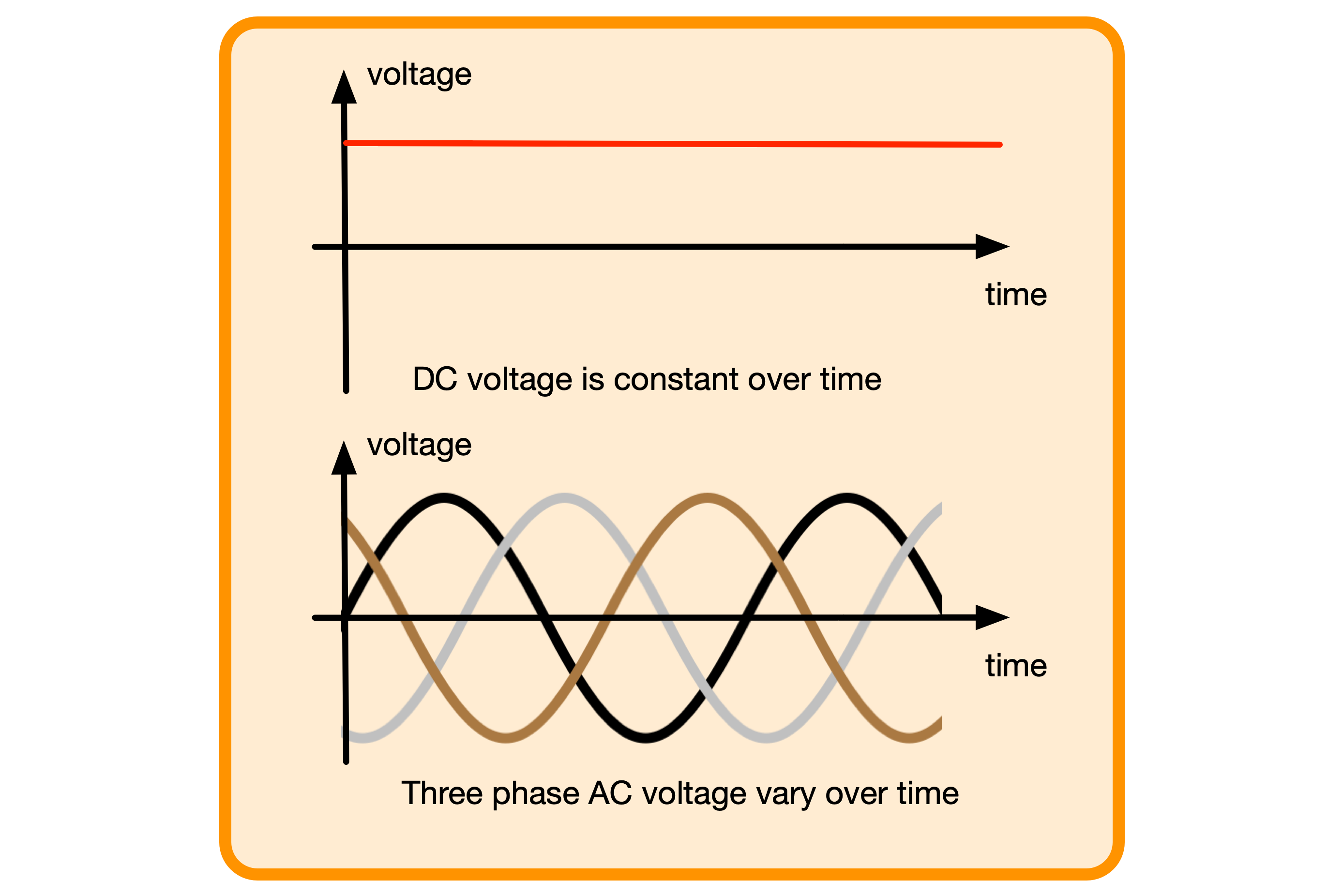
There are DC voltages and AC voltages in electric cars. We have DC for storage in the battery and AC when we want the motor to work. We’ll get to how we deal with those two different systems later.
Now let’s look at the components that make up an EV.
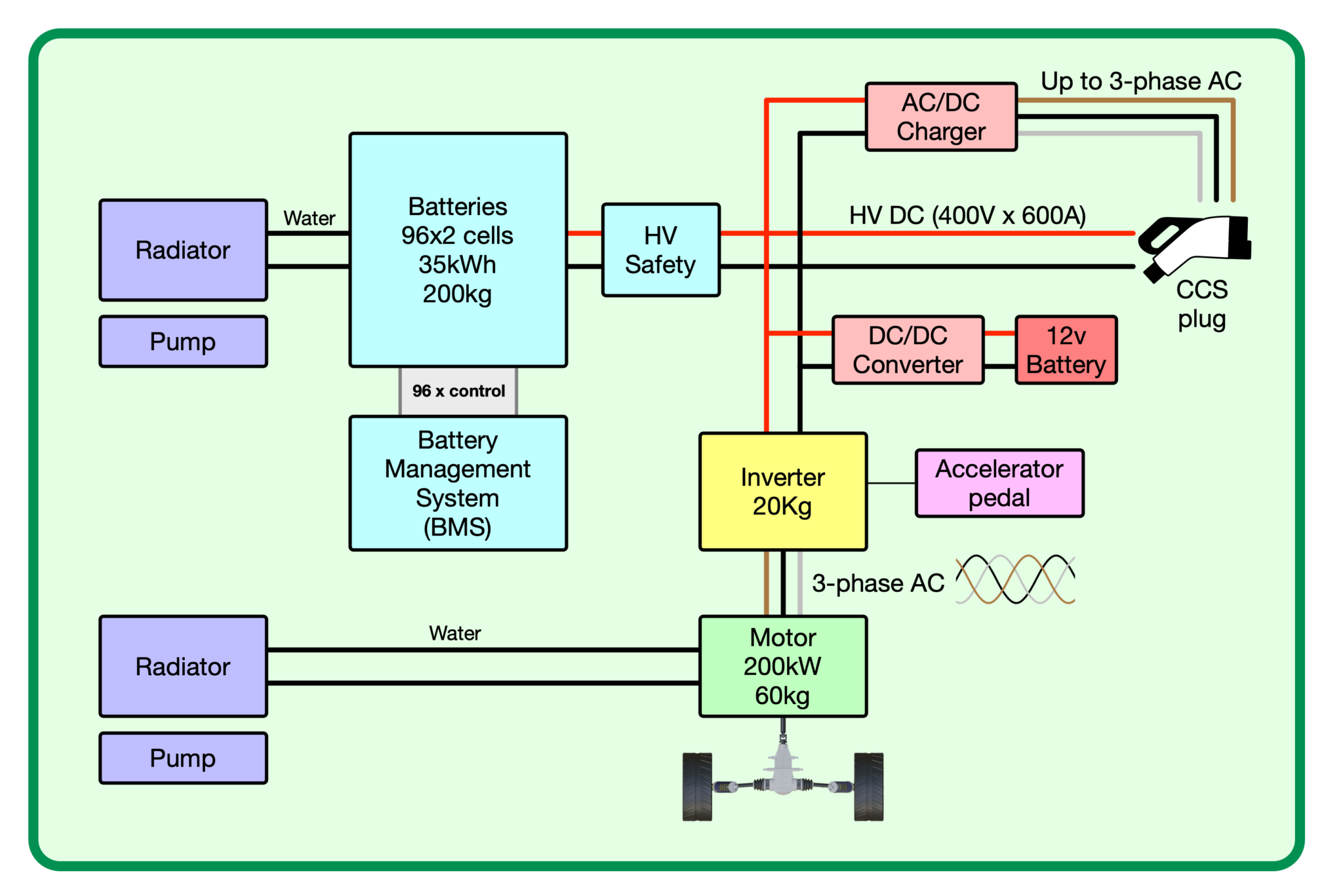
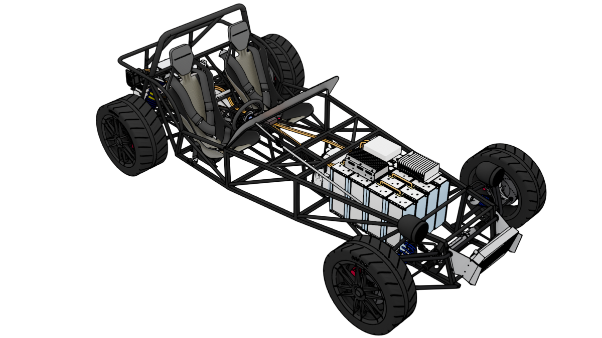
Layout note: make this overview diagram bigger than the DC/AC and chopping diagrams
Motor
The first component to look at in an EV is of course the motor. There are several different motor designs, (seven mains ones) that get used in our modern lives, each having pros and cons. There are even some DC motor designs which are now no longer used by EVs (aka milk-floats), so we’ll concentrate on AC motors.
There are three basic designs of motor used in EVs — induction motors, permanent magnet motors and reluctance motors. You’ll be relieved to read that we won’t go into the differences here, but suffice to say, they are all multi-phase AC motors and are sometimes even used as hybrids combining aspects of two or more different types into one.
There are three key points that we will cover on AC motors though — voltage, current and frequency. They are designed to work best at a particular voltage, which is typically fixed in an EV. The current supplied to the motor flows through the wiring in the motor and when multiplied by the voltage, gives us the power the motor is delivering at any one time (as we discussed in the last article, P = I x V). And finally, the frequency of the voltage and current, i.e., how many sinewave cycles per second we have, defines what speed the motor runs at, its RPM. And like in an internal combustion engine (ICE) car, motor RPM translates into wheel RPM — the more revs per minute, the faster you’ll be going.
Another critical component of how a motor gets used in an EV is the torque the motor produces. This is in essence how we drive the car. As we put our foot down on the accelerator, we increase the torque we’re asking (demanding) the motor to produce. There’s a whole bunch more brain twisting we can do to tie voltage, current, frequency, torque, EMF, MMF and another term “flux” into how motors work, but we’ll leave it here and remind you that motors work on three alternating currents with a fixed voltage, variable current and variable sine wave frequency.
When talking about motors it’s also worth noting that they’re not perfectly efficient. They’re good, with around 95% efficiency, but they’re not perfect. And when you’re trying to deliver somewhere between 100 and 200kW of power (134 to 268BHP), that 5% efficiency loss translates into heat. That heat can build up and cause problems, so motors need to be cooled if you want them to generate a lot of motive power for long periods.
Battery
We talked about batteries somewhat in the last article, so I won’t rehash what I wrote then. But as I mentioned above, batteries are inherently DC devices. They store energy at a (mostly) constant voltage and deliver it as direct current. This also applies to their charging which happens using a DC voltage.
Battery usage in EVs varies from platform to platform (like ICE cars, manufactures tend to use a platform for their range of cars, varying wheelbase and body style, but keeping major “architecture” the same). But let’s take a common example and say that an EV battery is often configured to give a nominal (designed for) voltage of 400V.
To make up the 400V and 500A we want (that’s about 200kW), our battery will have “cells” arranged in series and parallel. A 400V lithium-ion battery might have 96 cells in series and 2 or 3 banks of 96 cells in parallel. This is further complicated in a conversion project because currently, the easiest way of getting lithium batteries is in modules. A module typically has 12 cells which could be arranged as three series, four parallel (3S4P), four series, three parallel (4S3P) or any other combination that adds up to twelve cells (6S2P, 2S6P, 12S1P). We then take many modules and arrange them into our car to give us one big battery pack of 400V.
We covered a lot of the motor and battery specifics in the previous article, but while those two components are the major parts of our car, we also need some supporting components that are no less important. You could consider the battery as like the fuel tank in an ICE, the motor as the engine and the other ancillaries are the equivalent of the water pump, fuel pump, alternator, radiator and loom.
The battery pack of an EV is the single biggest and most expensive part of an EV. An EV will do around three to four miles per kWh, so for a range of over 100 miles we’ll need over 30kWh which means a weight of around 200kg and a cost close to £10,000.
Inverter and Motor Controller
Often referred to as just the inverter, this component is much more than the literal definition of an inverter — which is a device to convert AC into DC. In an EV, that term has been expanded to incorporate the motor controller and we’ll talk about them here as two separate items.
Inverter: The inverter’s job here is to convert high voltage DC into 3-phase waveforms. The exact method by which it does this is perhaps something we can come back to in a future article, but for the moment we can say that to get three different waveforms from a single non-changing DC voltage, the inverter rapidly switches the input DC voltage on and off, creating what is known as a chopped output (see fig. 4). This is then smoothed to create a sinewave. Three sinewaves are created, each offset by ⅓ of a cycle to create the three phases (brown, black and grey in fig. 2) needed to drive the motor.
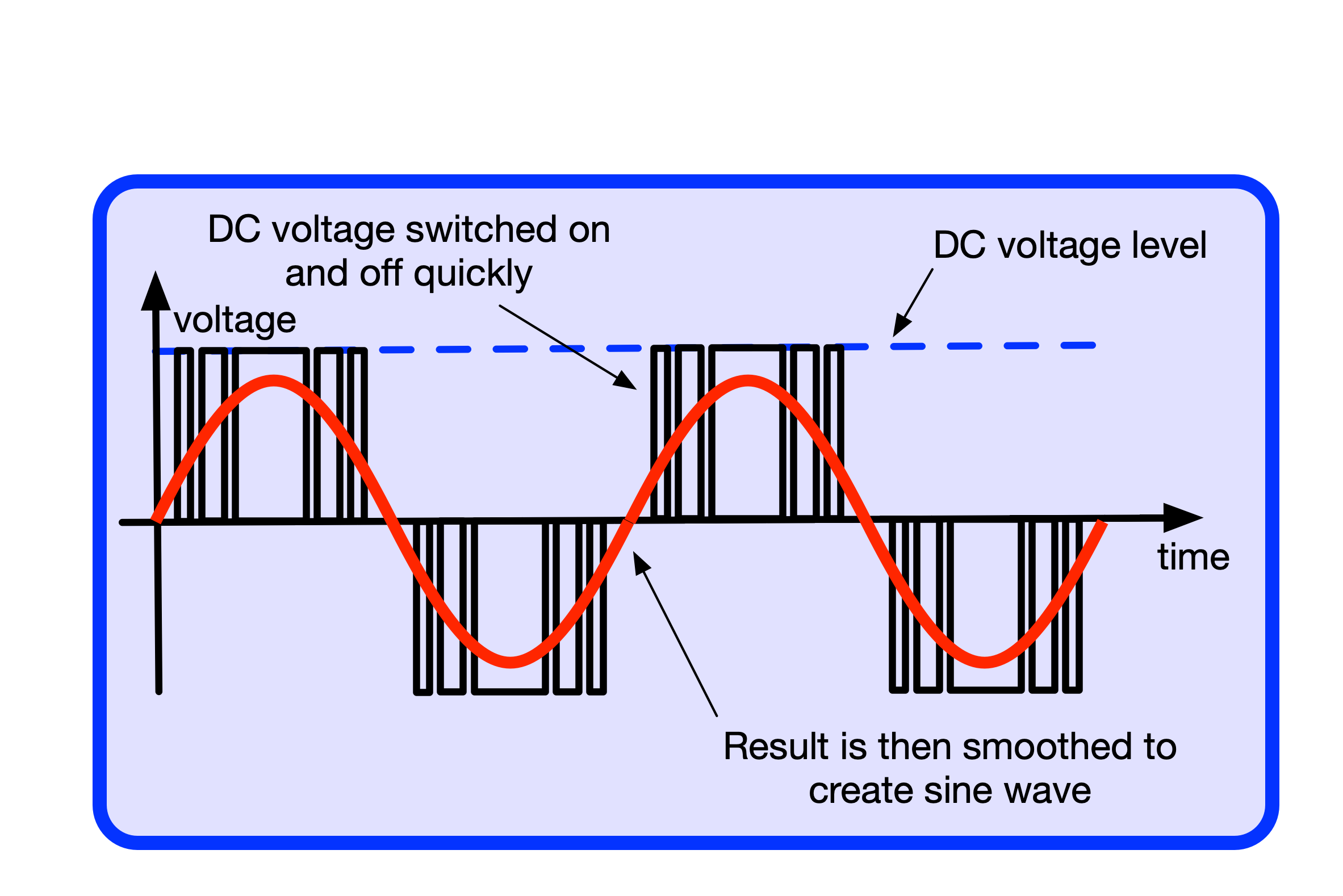
Motor Controller: The tricky bit is not just to create the three sinewaves but to do it at the right frequency and phase. This is the job of the motor controller. The frequency (how many cycles the sinewaves perform per second) will directly relate to the speed the wheels are turning at, and because there’s no clutch on an EV, when the car is stationary, the motor needs not to be turning. When the driver puts their foot down on the accelerator, the motor controller must start creating sine waves, at the right frequency. Some simple maths will tell you that you need hundreds of sine waves per second so that the wheels will turn at up to 2,000 times per minute. Therefore, the motor controller needs to turn the DC voltage on and off many thousands of times a second. Not only that, but the motor controller is often not just trying to create sine waves — that’s a simplification, it’s trying to create much more complicated waveforms and having to perform significant amounts of maths to do so… around 20,000 times a second.
Because of the currents involved and the power being switched, the inverter is quite a sizeable piece of electronics. Like all electronics, it’s not 100% efficient, and if you’ve followed this journey so far, you’ll know that inefficiencies turn into heat, so like the batteries and motor, inverters also often need to be cooled.
BMS
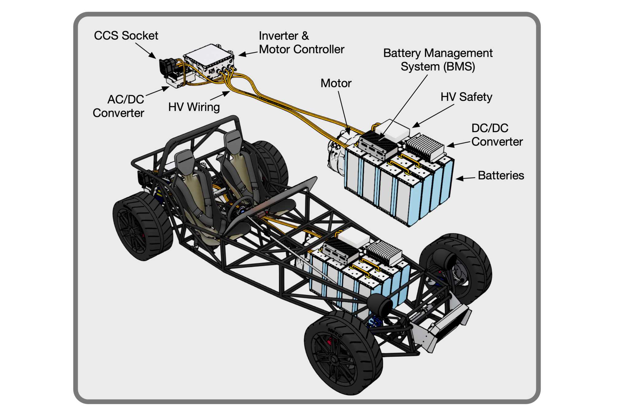
As well as the motor controller, an EV has a second controller “brain” which is used to manage the battery system (BMS — battery management system). The lithium cells used in modern EVs are not as forgiving as the lead acid batteries we’ve used for decades in ICE cars, and need to be charged and discharged carefully. This is the job of the BMS which monitors each group of parallel batteries (remember, there are groups of cells arranged in parallel and series) and checks their voltage to make sure they’re being charged and discharged correctly, safely and with longevity in mind. The BMS also monitors the temperature of the battery packs and will alter the charging profile to make sure they are not being charged too quickly and generating heat that might in a worst-case scenario cause thermal runaway (the batteries getting hotter and hotter on their own accord) and creating a fire.
It’s perhaps worth pointing out that managing the temperature of the batteries is not just about trying to keep them cool. In freezing conditions, it often makes sense to warm the batteries to an optimum charging temperature, so, the battery coolant circuit may also have a heating element attached to bring the battery pack’s temperature up, as well as a radiator to take it down.
The BMS will also communicate with the motor controller, telling it if the battery pack is too hot and therefore needs to back off on the power delivery (that’s why some EVs can only do a few 0-60 runs). It will also talk to the AC/DC and DC/DC charging components when the car is being charged, again telling them when to back off the charging power, mainly to boost battery pack longevity and to keep them cool.
The BMS also acts as the master safety controller for the car, controlling the main contactors for instance – see safety below.
Charging Circuitry
We’ve talked about how we store electricity in the battery and then take it out to use in the motor, but how do we get the electricity into the batteries to charge the car?
As well as the motor inverter doing voltage conversions (DC-to-AC), we also have a component that charges the 12V battery (a DC-to-DC converter) and one that can charge the main HV (high voltage) battery from AC (AC-to-DC converter). Finally, there’s also a component that can manage another way of charging the HV battery (DC charge management).
DC-to-DC charger: Let’s start with the 12V battery charger. You might think with all this high voltage power electronics floating about you wouldn’t need a 12V battery in an EV. Well, that turns out not to be the case. There are a few reasons why you’d want a 12V battery: 1. It’s much simpler to re-use all the headlights, indicators, cabin fan, windscreen heater, windscreen wipers, washer motor etc, from the nearly 100 years of automotive know-how, and they run on 12V (mainly).
- If the HV system fails, or runs flat, you need something to run your hazards, cabin heater, central locking etc (obviously some not needed on a Seven though!) And if the HV battery is flat then you need another power source to run the charging circuitry to get that main battery going again. To accommodate those requirements, it makes sense to keep 12V around in the car and for it to be from a 12V battery. This is where a DC-to-DC converter comes in — converting 400V down to 12V and charging the 12V battery; there’s no alternator in an EV, so charging the 12V battery has to come from somewhere else. For a Seven, the size of this converter could be modest. For regular EVs, it could be quite large when you consider air conditioning systems and cabin heaters. But for us a 1kW DC/DC converter should do.
AC-to-DC charger: Next, we have a converter that takes AC from a CCS charging socket (Common Charging System — a mostly worldwide standard) and converts it to DC to charge the HV battery, that’s domestic 220V single phase or three phase being converted to 400V. You’ll notice there are two AC power delivery options here. The CCS charging socket, that all EVs support in the EU now, can provide three charging scenarios. You can hook it up to your home charger with, usually, single phase power up to 7kW, connect it to a three phase AC outlet for 21kW charging (which can be at home but is usually a non-domestic charging station), and finally, CCS provides two DC connectors for fast charging up to 350kW — very much not a domestic home supply!
An AC-to-DC converter that we’re talking about here is for the first two AC charging types. This charger might even be an optional item for a Seven — an AC/DC converter is bulky, heavy and only needed when charging at home. If, as a Seven driver, you had a portable AC-to-DC converter and could rely on fast charging when you’re out driving then maybe this component can be left in the garage. Even if included, it could be a small, low power device, that you only use overnight when a ten-hour charging session is OK.
DC to DC Management: Finally in this talk about voltage converters we have a bit of an odd ball, a DC fast charge manager. If we want to rely on fast charging (especially if we don’t install an AC/DC charger as discussed above) then we’ll want to fast charge. By fast charging I mean charging up to 350kW (though for various reasons I wouldn’t expect to be able to charge a Seven conversion above about 40kW now). Fast DC charging uses both the top and bottom parts of the CCS connector. The top connections provide the communications between car and charger, while the power delivery takes place using the bottom two connectors. The communications between car and charger make sure the right voltage and current are supplied to the car and are done in conjunction with the BMS, considering battery temperature and longevity. The critical thing to bear in mind here is that the DC-to-DC manager is asking the road-side charger to supply the correct voltage for the car – there’s no conversion to, or from, AC and no voltage level change.
Cooling
One rather nebulous component of an EV is its cooling (and heating) circuits needed for the batteries, motor and inverter. If you’re operating your EV at low-ish power, not taking it to the track or doing 0-60 tests all the time, then you may get away without any cooling at all. That statement is probably only true for something as light and minimal as a Seven and only so for someone doing a conversion. Any commercially saleable EV will want to include cooling: for people who want to drive their cars in the winter for instance or for that matter belting down the autobahn in Germany. There’s also a bit of idiot-proofing going on here, including cooling for the temperature “sensitive” components means the car can operate in more conditions for longer and with the driver having to worry less about the differences between an EV and an ICE car.
High Voltage (HV) Safety and Wiring
Finally, let’s talk about a catch-call category. I’ve lumped together something I’ve called HV safety and HV wiring.
HV Wiring: The HV wiring is simple but does need to be thought about carefully. It distributes both DC and AC power around the car at a peak of around 400V and 600A and can often need to run that sort of power from front to back of the car a few times — mainly because of constraints around packaging the main bulky components.
There’s a lot of power being distributed around an EV and if you chose the wrong wiring size for your HV then it’s quite possible to lose 500W or so in a single length of cable. Not only is that going to hit your efficiency it’s also going to make some bits of the car toastier than you thought they’d be. It’s also worth pointing out that all HV wiring needs to be orange. So, when you see orange cabling in your EV, you know that’s the high voltage stuff and you really need to keep clear of it unless you know what you’re doing.
HV Safety Components: I’ve lumped a few things here into this component. Most EV conversions have at least one box of goodies that houses a few critical but otherwise disparate components. Included in this we have things like pre-charge circuits (that protect the inverter when applying HV to it on start-up), contactors (that are a fail safe for a few areas of the car) and sometimes interlock wiring that I’ll talk about in a bit.
Contactors: The contactors are perhaps interesting to talk about and are essentially just high voltage relays, a switch, that either allows the flow of current or not and work for both DC and AC circuits. An EV will typically have contactors spread throughout the HV circuits protecting you and other parts of the car if faults or accidents occur.
If you’ve ever started or stopped an EV, or plugged one in to charge, you’ll have heard a loud series of clicks. This is the contactors energising or de-energising. If the contactors aren’t energised, then nothing will work in an EV and there will be no power distributed around the car. Before you can move off in an EV, the car has to perform its diagnostic checks and will only engage the contactors if all those tests pass. It will also run similar checks before it will allow a charging session to start when it will also engage the contactors. Furthermore, if any fault occurs during running or charging the car then the contactors will disengage (de-energise) with the intention of keeping everything, and everyone, as safe as possible.
Interlocks: Which leads us to a very important concept in EV cars and one that should be high priority for any Seven conversion: interlocks. All EVs have at least one interlock system that, when tripped, will disengage the contactors and turn the car off. An interlock is a long physical wire that connects through each of the EV’s components, stringing from one device to the next in series. It runs through all the HV connectors and is present on each of the lids or containers of any HV component.
For instance, not only does each HV connector (plug or socket connecting some HV wiring to a charging circuit, inverter, motor, etc) have contacts for the high voltage to pass through, it also has a pair of interlock connections. These are arranged so that if the connector is opened (you pull the plug on your HV battery for instance) then the interlock connections disconnect before the high voltage does. In that split second between the interlock being disconnected and the HV being disconnected, the interlock system will disengage all the car’s contactors and means that as you withdraw the plug from the socket there is no voltage on the HV connections by the time you get to the point where you can touch them. The interlock works in a similar way for items like the battery box cover where the interlock is again set to disengage the contactors before anyone can take the lid off far enough to expose any HV circuitry. Interlocks are very important.
Conclusion
That’s it for this episode.
Thanks to Equipmake for providing 3D models of their motors.
See you next time when I’ll have started to do some converting.



Leave a Comment