Communications protocols are often called protocol stacks… they’re layers, or stacks, of different protocols… one layered on top of the other from lowest level (hardware/physical) to highest level (software application).
This is where the OSI 7 Layer model comes in… it standardises how we think about the layers and allows us to talk about where each protocol and hardware/software sits in the layer stack.
More info on the OSI 7 Layer Model can found here.
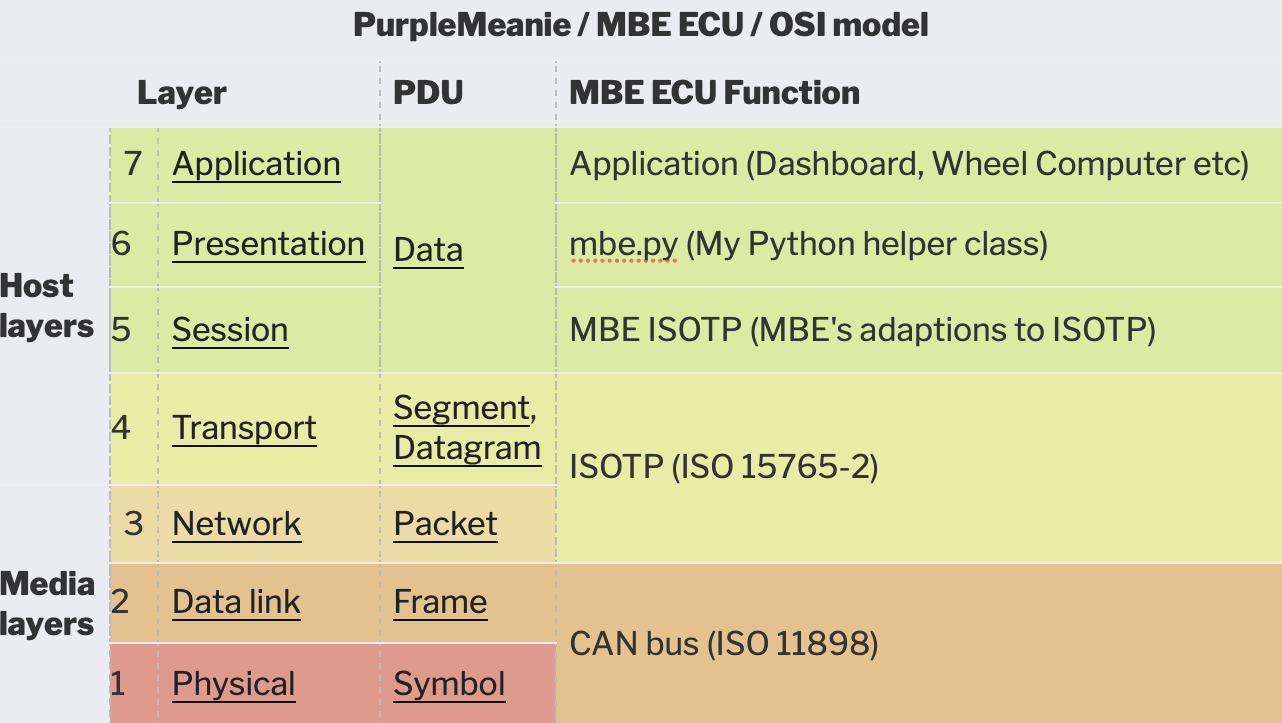
If we now load the OSI model with the layers for the MBE ECU protocol stack then the table looks like this:

From the table above…
MBE ECU OSI Function
Application
At the highest OSI level we have the application layer. This is what the user sees, turning all the lower level layers into something pretty to see.
mbe.py
This is my helper class. It takes the more complicated layers below and provides a simpler abstraction layer for the application to use.
MBE ISOTP
I’ve called this layer the MBE ISOTP layer. It adds a communication layer on top of the ISOTP packetization layer. This MBE ISOTP layer provides “commands” for config and data extraction from the ECU. It does so “on top” of the ISOTP layer below, or another way to think of it is to say the MBE ISOTP packets sit “inside of” of the ISOTP packets.
ISOTP
This is the standard used to extend CAN bus packets from 8 bytes up to a maximum of 4095 bytes per packet and sits on top of the CAN bus protocol.
It also provides for an additional paradigm called flow control. In theory flow-control should allow CAN bus devices to negotiate the timing between CAN bus frames that each device can support.
HOWEVER – The MBE/SBD Easimap and ECU… DO NOT USE FLOW CONTROL. This caused us some concern to start with and meant we had to adjust some of the ISOTP libraries we were using, see here.
CAN Bus
We’ve talked about this layer a lot, the most relevant post about it can be found here.


Leave a Comment